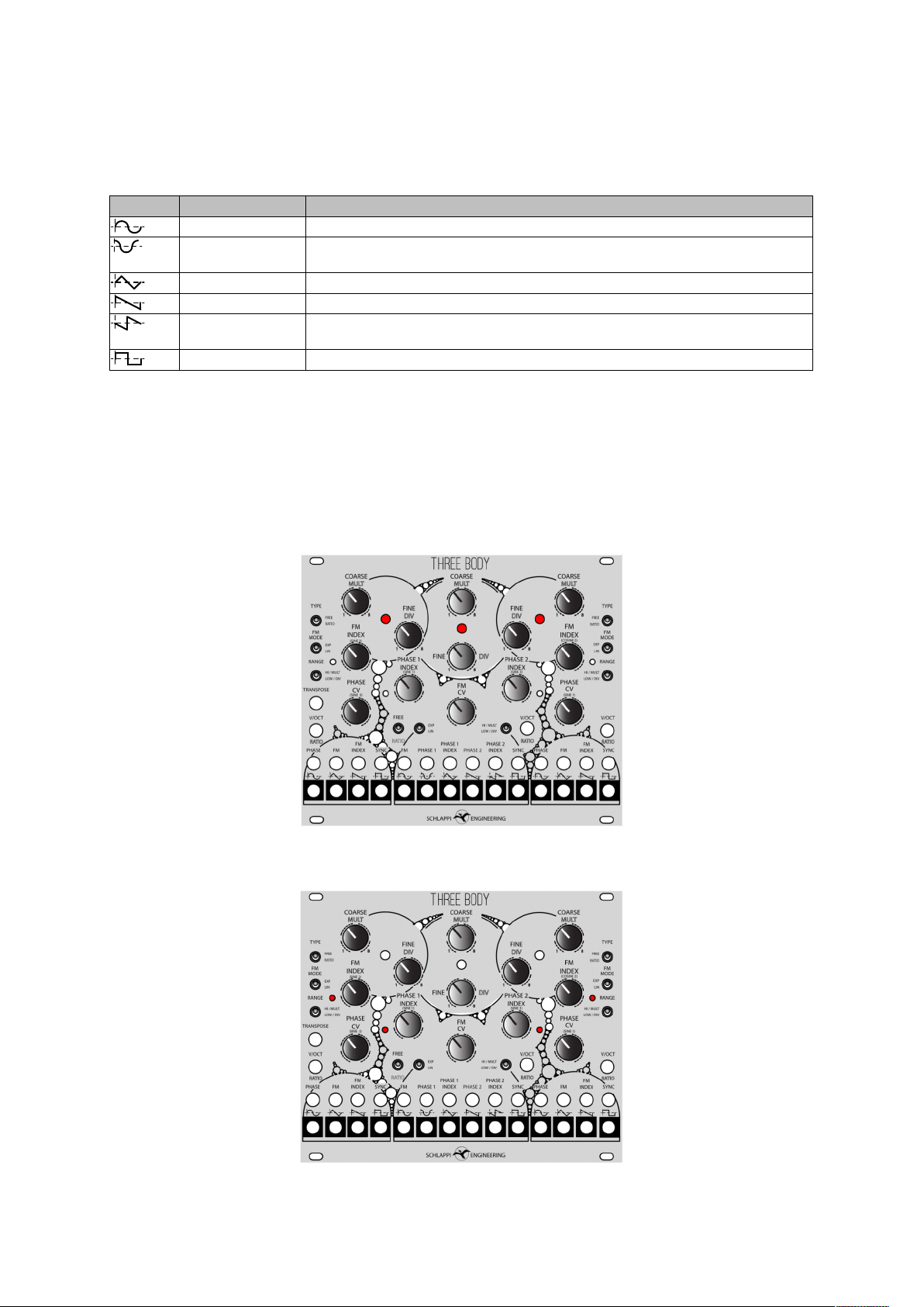
SCHLAPPI ENGINEERING THREE BODY User manual

THREE BODY MANUAL
S
C
H
L
A
P
P
I
G
N
I
R
E
E
N
I
G
N
E

Technical Information 3
Voltage Levels 3
Sample Rates and Bit Depth 3
Current Draw 3
Module Description and Features 4
Introduction 4
Block Diagram 5
States 6
Controls 7
Inputs 7
Outputs 8
Indicators 8
Modulation Normalization 9
Ratio Normalization 9
Patches to start exploring with: 10
Unmodulated Ratios 10
Phase modulation with ratios 11
Stereo Frequency modulation 12
Theory and Usage 13
Phase Vs Frequency Modulation 13
Through-Zero Eects 14
Modulation Depth 15
Cross Modulation 16
Phase Related Outputs and Stereo Usage 17
External Tracking 19
Conguration Headers 20
Calibration 21
More Recommended Patches 22

Technical Information
Voltage Levels
The Three Body is designed for compatibility ith Eurorack voltage standards. Inputs are
scaled to certain ranges to optimize ADC precision. Inputs and outputs are voltage and
current protected and should not but damaged by any level ithin the Eurorack ecosystem
(-12V to +12v, or 24v peak to peak).
All inputs and outputs are DC coupled.
Sample Rates and Bit Depth
All inputs are sampled at 12bit 96kHz but volts per octave and indexes are over sampled to
achieve 14 bit precision at the expense of a lo er eective sample rate closer to a fe
kilohertz.
The internal sample rate of the Three Body audio path is 12.5MHz to achieve lo aliasing
and high quality modulation eects.
The outputs are implemented ith delta sigma modulation on the FPGA itself and are
approximately 16 bit quality ith 96kHz sample rate.
Current Draw
+12V: 95mA
-12V: 50mA
Inrush current on +12V: approx 200mA
The Three Body has been designed for low power usage, however it will draw a bit
more current on startup than during operation as indicated by the inrush current listed
above.
SIGNAL TYPE LEVEL Notes
Volts per octave CV input -8V to +8V Best tracking between -5V and +5V
Phase or frequency CV
input
-8V to +8V Will clip bipolar signals above 16 volts peak
to peak or unipolar inputs above 8V
Index CV input 0 to 10V Unipolar inputs for envelopes, will clip
below 0V and above 10V
Sync input 0.7V
threshold
Comparator input stage triggers around
0.7V
Output -5 to 5V All outputs are bipolar 10V peak to peak (or
slightly higher, up to 12V peak to peak)

Module Description and Features
Introduction
The Three Body is a phase and frequency modulation toolkit, designed to bring digital
techniques to an analog interface.
It consists of three oscillators hich can be used independently but hich have normalized
connections to facilitate exploration and improvisation.
The separate oscillators can be identied by diering knobs colors and the boundaries
sho n in the panel design.
Each oscillator has three s itches to dene it’s state (or mode) as ell as a collection of
inputs and outputs (identied by the boxes around the jack).
SCHLAPPI ENGINEERING
THREE BODY
FREE
PHASE FM
FM
INDEX SYNC
V/OCT
FM PHASE 1
PHASE 1
INDEX SYNCPHASE 2
PHASE 2
INDEX PHASE FM
FM
INDEX SYNC
COARSECOARSE COARSE
FINEFINE
FINE
FM
INDEX
PHASE 1
INDEX
PHASE 2
INDEX
PHASE
CV FM
CV
PHASE
CV
TRANSPOSE
(COSINE 2)
FREE
TYPE
LIN
EXP
RANGE
LOW / DIV
HI / MULT
LIN
EXP
LOW / DIV
HI / MULT
TYPE
FM
MODE
RANGE
FREE
LIN
EXP
LOW / DIV
HI / MULT
FM
MODE
FM
INDEX
(SINE 2)
V/OCT V/OCT
(SINE 1) (SINE 3)
(SINE 3) (SINE 1)

Block Diagram
OUTER
OSCILLATOR
VCA
FREQUENCY IN
PHASE IN
(CENTER
SINE)
(OPPOSITE SINE)
(10V)
FM INDEX
VOCT/RATIO
SYNC
COARSE/
MULT
FINE/
DIV
FM IN
PHASE IN
WAVEFORM
OUTS
OUTER
OSCILLATOR
VCA
FREQUENCY IN
PHASE IN
(CENTER
SINE)
(OPPOSITE SINE)
(10V)
FM INDEX
VOCT/RATIO
SYNC
COARSE/
MULT
FINE/
DIV
FM IN
PHASE IN
WAVEFORM
OUTS
VCA
CENTER
OSCILLATOR
VCA
(10V)
(10V)
(SINE L)
(SINE R)
PHASE 2 INDEX
PHASE 2
PHASE 1
PHASE 1 INDEX
VOCT/RATIO
SYNC
COARSE/
MULT
FINE/
DIV
WAVEFORM
OUTS

States
At the heart of the three body is a digital logic state machine ith 8 states (per oscillator)
dened by three s itches (per oscillator). This determines hether the oscillator is free,
operating much like an analog oscillator, or tracking in a ratio mode as is necessary for
Cho ning style digital FM. It also determines the behavior of the VOCT/RATIO CV,
frequency modulation, and sync inputs.
Each oscillator also has a phase modulation input hich is not state dependent and a SYNC
input. In FREE mode the SYNC input ill act as a classic hard sync and in RATIO mode the
oscillator ill track hatever signal is at the SYNC input.
FREE/
RATIO
EXPO/
LIN
LOW/HIGH/
DIV/MULT
DESCRIPTION
FREE EXPO LOW LFO with exponential frequency modulation
FREE EXPO HIGH VCO with exponential frequency modulation
FREE LIN LOW LFO with linear frequency modulation
FREE LIN HIGH VCO with linear frequency modulation
RATIO PHASE DIV Tracking oscillator with phase modulation and CV
over division
RATIO PHASE MULT Tracking oscillator with phase modulation and CV
over multiplication
RATIO LIN DIV Tracking oscillator with linear frequency modulation
and CV over division
RATIO LIN MULT Tracking oscillator with linear frequency modulation
and CV over multiplication
TYPE
MODE SWITCHES
for each oscillator
FREE
RATIO
FM
EXPO/PH
LIN
HI/MULT
LOW/DIV
RANGE

Controls
Controls aected by the FREE/RATIO state, works the same for each oscilllator.
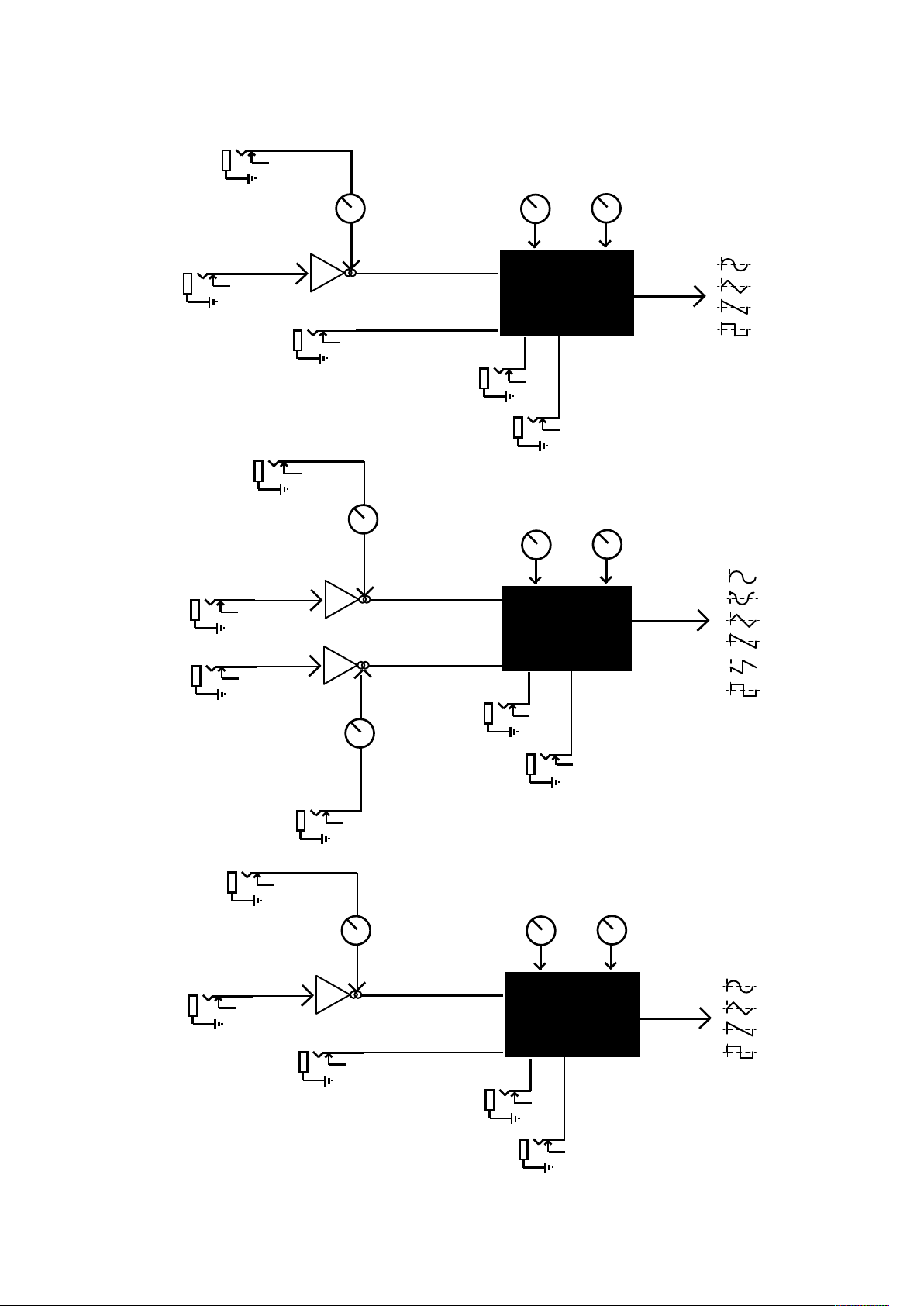
Modulation controls are the same for the outer oscillators, but the inner oscillator has
an extra phase input and index control (VCAs) on phase modulation instead of
frequency
Modulation inputs are the same for the outer oscillators, but the inner oscillator has
an extra phase input and index control (VCAs) on phase modulation instead of
frequency
Inputs
Inputs aected by the FREE/RATIO state, works the same for each oscillator
CONTROL FREE RATIO
COARSE/MULT Coarse pitch control Tracking multiplier
FINE/DIV Fine pitch control Tracking divider
INPUT FREE RATIO notes
TRANSPOSE Global Volts per octave
input, adds to all
oscillators pitch
Has no eect Aects all oscillators in
free mode, including
those in LFO mode
VOCT/RATIO Volts per octave input CV adding to
multiplier or divider
Bipolar, can be used at
audio rate
SYNC Hard sync Tracking input threshold at 1V, tracks on
rising edge
INPUT RATIO
PHASE Phase input, breaks internal normalization
PHASE
INDEX
CV control over amount of phase, breaks normalization to 10V Outer osc
FM Frequency modulation input, expo or lin, breaks internal
normalization
FM INDEX CV control over amount of phase, breaks normalization to 10V Inner osc
CONTROL DESCRIPTION Oscillator
PHASE CV Attenuator over phase input outer
PHASE INDEX 1 Attenutor for CV control over amount of phase input 1 inner
PHASE INDEX 2 Attenutor for CV control over amount of phase input 2 inner
FM CV Attenuator for amount of FM input inner
FM INDEX Attenuator for CV control over amount of phase input outer
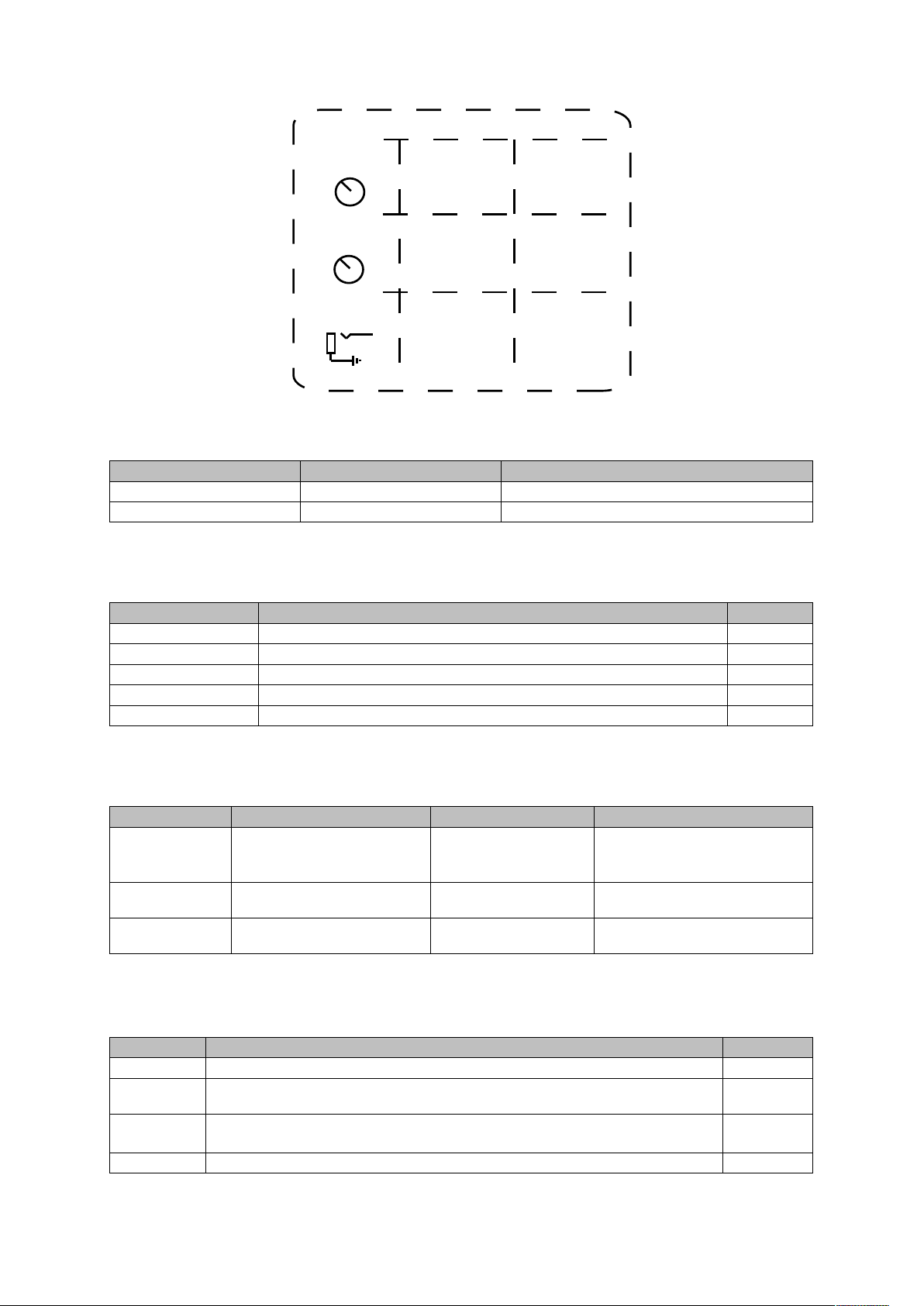
FREE
COARSE
PITCH
CONTROL
FINE
PITCH
CONTROL
VOLTS
PER
OCTAVE
CV
COARSE/
MULT
FINE/
DIV
VOCT/RATIO
TRACKING
MULTIPLIER
TRACKING
DIVISOR
RATIO
CV
RATIO

Outputs
All outputs are bipolar, approximately 10V peak to peak (may be a bit higher), and
aected by the phase or frequency modulation of the related oscillator.
Indicators
The three large LEDs across the top are all tied to the respective sine wave output of
that oscillator. When this oscillator is below audio rates it will show blue when positive
and red when negative and when at or above audio rates it will show as some
variation of purple.
The four small LEDs across the middle are all tied to the output of the index VCA
next to it. This way you will see both the intensity and the rate of the modulation.
LABEL NAME DESCRIPTION
SINE Sine wave output, modulation subtracting from the phase
COSINE Cosine output, 90 degrees oset ahead of sine output with
modulation adding to the phase. center oscillator only
TRIANGLE Triangle wave output, modulation adding to the phase
SAW Sa ave output, modulation subtracting from the phase
COSAW Saw wave 90 degrees oset ahead of saw output with
modulation adding to the phase. center oscillator only
SQUARE Square wave output, modulation subtracting from the phase

Modulation Normalization
While the three oscillators can be used totally independently, there are some normalization
in place to aid easy exploration as a stereo fm oscillator, drone bank, or even a standalone
noise box.
The inner oscillator PHASE inputs are normalized to received modulation from the outer
oscillators sine outputs.
The outer oscillators FM inputs are normalized to the inner oscillators sine (for the left side)
and cosine (for the right side).
The outer oscillators PHASE inputs are normalized to the opposite outer oscillators sine
ave output (so the left sine goes to the right phase in, and the right sine out goes to the
left phase input).
Ratio Normalization
The t o outer oscillators are set to track the inner oscillator if set to RATIO mode ith no
cable plugged into their respective SYNC jacks.
CENTER
OSCILLATOR
NORMALIZATION
PHASE
PHASE
PHASE
FREQUENCY
PHASE
FREQUENCY
RIGHT
OSCILLATOR
LEFT
OSCILLATOR
RATIO TRACKING
RATIO TRACKING

Patches to start exploring with:
Unmodulated Ratios
Start with all modulation related controls fully counter clockwise. Listen to a sine or
triangle output from the center oscillator as well as one from the right oscillator.
Set the center oscillator to “free” and “high” and the right oscillator to “ratio”.
If the division (the FINE DIV knob) of the right oscillator is set to one (fully counter
clockwise) then turning the multiplication (COARSE MULT) will travel up and down
the harmonic series.
If the division is set higher than one then changing the multiplication value will travel
through a scale of sorts, moving in half octave intervals in the case of a division of 2,
or third octave ratios in the case of a division of three.
Next take a modulation signal like an envelope or LFO, attenuate it with an attenuator
or VCA (this is important) and plug it into the V/OCT RATIO input of the right
oscillator.
Depending whether the range/ratio mode switch is in LOW/DIV or HIGH/MULT this
will add to either the multiplication or division value. If you attenuate the signal
enough you can limit it to only one or two values which will create an arpeggiation
eect if both the mult and div knobs are set fully counter clockwise.
Try also setting the left oscillator to ratio mode and listening to all three oscillators
while sending CV to the outer oscillators, depending on the modulation this can turn
into a wall of arpeggios or slowly moving harmonic drones.
A variation is to set the center oscillator to ratio as well and plug an external oscillator
into the SYNC jack. The center oscillator will then track the external oscillator at a
ratio and the other two oscillators will still track the center oscillator (unless you mult
the external signal and run it into those SYNC jacks as well, then they will track it
instead).

Phase modulation with ratios
Start with the ratio patch as above but listen to the sine and cosine outputs of the
center oscillator instead. Bring up the PHASE INDEX 1 and PHASE INDEX 2
controls (making sure all other modulation controls are down.)
You should be able to hear the ratios or modulated arpeggios through the center
oscillator but as phase modulated timbre changes instead of directly (listening to the
outside oscillators).
If you bring up the PHASE CV controls (carefully, less than halfway) of the outside
oscillators then they will cross modulate each other resulting in high harmonic
content, even if you are just listening to the center oscillator.
If you bring up the cross modulation too high it will disintegrate into noise, but just a
little can really bring life to a patch.
A nice variation is to set the left oscillator to free and low mode so it becomes an
unsynced lfo (you may want to remove any modulation that may have been plugged
into the V/OCT RATIO jack). If you are still listening to the sine cosine pair your patch
should gain a large stereo element.
When you have done all this try also listening to the saw and cosaw outputs of the
center oscillator, you will also get a large stereo eld but with much more harmonic
content.

Stereo Frequency modulation
Put the outer oscillators into ratio and linear fm modes, put the divide controls fully
counter clockwise and the multiply controls at noon or higher so they are at a
signicantly higher frequency than the center oscillator. You may want the center
oscillator to be in a pretty low register so this isn’t too painful.
Make sure all modulation controls are fully counter clockwise.
Take the outputs from the outer sine wave outputs, this will give us our nice clean
sine wave fm.
Now (slowly) turn up the FM indexes of the outer oscillators, you should hear a
gradual build up of harmonics.
Next insert a modulator like an LFO or envelope into the FM index inputs.
With very slow modulation on the FM index you should have a deep and ever
changing timbre.
Next try changing the frequency of either the carriers (the outer oscillators) or the
modulator (the inner oscillator). You may nd that if the index is high enough the
fundamental is eectively erased and it doesn’t matter very much what frequency the
carriers are as long as they are higher than the modulator, they act more as a lter
for the modulation than independent oscillators.
If you want a little more spice on the sound add some cross phase modulation
between the outer oscillators.
FM INDEX

Theory and Usage
Phase Vs Frequency Modulation
A traditional digital oscillator (direct digital synthesis or DDS) is accomplished with an
accumulator. The accumulator can also be thought of as a counter, where each clock
tick some amount is added to the counter along with the previous value of the
counter. This can be visualized as a stepped sawtooth waveform.
Frequency modulation is accomplished by changing the amount that is added to the
accumulator each clock tick, which results in a change in pitch. However the
accumulator (a digital version of an integrator) acts as a lter on the modulating
frequency. This means that the modulator should be a lower frequency than the
carrier and also that DC osets can aect pitch.
Phase modulation is accomplished by adding to the output of the accumulator (a
triangle wave representing phase) before entering the waveshaper. By simply adding
to the phase value you get an eect closely related to frequency modulation (a
spreading of the power spectrum from the harmonic to various harmonic or
inharmonic partials depending on whether the modulation or carrier are related by a
simple ratio or not) but without pitch change with DC osets or the ltering eect
caused by the integration.
Another eect that phase modulation is closely related to is wavefolding, as the eect
of rolling over the register (moving the phase past 0 or 180 degrees) is analogous to
“folding” the waveform back over once a threshold is reached.
FM BY SAW OF
SAME
FREQUENCY
PM BY SAW OF
SAME
FREQUENCY
REGISTER REGISTER WAVESHAPER
(LOGIC OR LUT)
PHASE
ACCUMULATOR
PHASE ADDER
PHASE
INCREMENT
(FREQUENCY
WORD)
PHASE
MODULATION
FREQUENCY
MODULATION
WAVEFORM
OUTPUTS
0
0
0
0
0
1
0
1
0
0
1
1
1
0
0
1
0
1
1
1
0
1
1
1

The guidelines I keep in mind when using frequency and phase modulation are:
• With frequency modulation: The modulating frequency must be below the carrier
frequency (or it will be attenuated or disappear completely).
• With frequency modulation: Low frequency (below audio rate, including DC
osets) modulators will result in a change in pitch of the oscillator.
• With phase modulation the modulating frequency either needs to be in audio
range or you need to mix multiple outputs with dierent phases to hear the
modulation. Slow dierences in phase are not audible without a reference.
• With audio rate modulation (either frequency or phase) simple ratios are required
to create harmonic sounds. This may or may not correspond to musical ratios (or
scales).
Through-Zero Eects
The phase and frequency modulation in the Three Body are both implemented with
signed addition (or subtraction). This means the waveform can reverse direction if it
changes signs (or goes through zero). For phase modulation this is part of the
wavefolding action mentioned above. For frequency modulation this occurs when the
modulation index is large relative to the carrier frequency and can be seen on the
negative side of the modulating cycle.
FM EQUATION (FROM WIKIPEDIA) SHOWING MODULATION
INDEX DIVIDED BY MODULATION FREQUENCY
Consider that phase modulation is just adding t o aves
before a aveshaper, if they are not audible beforehand they
ill not be audible after ards (unless they are compared
against a reference, like in a phaser implementation).
SELECTED FREQUENCY RATIOS WITHIN A SCALE
1:1 UNISON
2:1 OCTAVE
3:2 PERFECT FIFTH
4:3 PERFECT FOURTH
5:3 MAJOR SIXTH
5:4 MAJOR THIRD
8:5 MINOR SIXTH
6:5 MINOR THIRD

Modulation Depth
Modulation depth (or index) increases the number of partials or harmonics that are
created and the relative spectral power of the partials to fundamental.
Holding the modulation depth steady and changing the modulation frequency keeps
the same number of partials but changes their spacing (spread in the frequency
domain).
Holding the modulation frequency steady and changing the depth keeps their
spacing but increases their number.
The modulation depths on the three body have been selected as a compromise
between eect, musicality, and usefulness within a system where cross modulation is
available.
Internally the linear frequency modulation and phase modulation have been greatly
amplied so that the linear FM is actually much stronger than the exponential FM. In
using the linear through zero FM you have the option to go so deep that the
fundamental is completely overwhelmed and some very satisfying sound design can
be reached, however you may want to keep the index pretty low if you are looking for
more traditional timbres.
The high amplication of the phase modulation also allows some non-traditional
timbres quite similar to wavefolding. The downside to this is that noise from the ADC
is amplied as well. To combat the high frequency noise I introduced some ltering on
the external phase inputs of the outside oscillators (which have no internal routing).
You can reduce this ltering (at the cost of additional noise) by using the “External
lter select” header 16 H.
AMPLITUDE
INCREASE
DEPTH
Fc Fc
AMPLITUDE
INCREASE
FREQUENCY
Fc Fc
FREQUENCY

Cross Modulation
Cross modulation is when one oscillator modulates another which is also modulating
it back. Cross modulating two or more oscillators will create a feedback loop and
greatly increase the perceived amount of modulation.
Cross modulating two oscillators with frequency modulation (either with frequency
modulation both ways or phase one way and frequency the other) will cause pitch
instabilities and rather unpredictable behavior. It may also cause one oscillator to
lock on to another or to cease oscillating independently. It is recommended not to do
this when you are attempting a melodic patch or looking for anything other than
unpredictability and chaos.
This is also one of the reasons that phase modulation was substituted for exponential
frequency modulation in ratio mode, the other is that exponential modulation with
ratios does not make a lot of sense (and was dicult to accomplish for various
technical reasons related to the architecture of the system).
Cross modulating two oscillators with phase modulation will drastically increase the
mount of high frequency content. With the default external lters this is tamed a bit,
with the external lter header on this can quickly get into shrieking territory and with
either lter pushing both other phase CVs up past noon will likely enter noise territory.
FM
EXPO/PH
LIN

Phase Related Outputs and Stereo Usage
The Three Body has two pairs of phase related outputs on the center oscillator. Sine
and Cosine, as well as Saw and Cosaw. No, “cosaw” is not a real term but it is
shorter than saying “a second saw wave ninety degrees out of phase with the rst”
and perhaps more relatable than using quadrature terminology.
In the Three Body these two sets of outputs are implemented with separate phase
adders, with the rst phase adder having the phase modulation inputs adding to the
oscillators phase counter and the second subtracting from it.
This has the eect of creating a wide stereo image with phase modulation, without
being likely to cancel in mono. Thus the sine and cosine can be used as one stereo
pair suitable for use as a voice where modulation is being used to add harmonics and
a lter is probably unnecessary.
The saw and cosaw outputs will also act as a stereo pair in situations where you
desire more base harmonics, something to for a lter to work with, or a dierent
tonality.
This somewhat unusual phase modulation arrangement does technically break the
phase relationship of the outputs. With modulation the sine and cosine outputs (or
saw and cosaw) are no longer 90 degrees apart from each other and thus the labels
are no longer accurate.
Another unusual implementation is that the triangle wave has phase modulation
applied in the positive direction (like the cosine and cosaw), this means on the
outside oscillators it moves in the opposite directions of the other waveforms. This
provides another tool to create complex waveforms with external mixing and
processing.

In case it is desirable to maintain the quadrature relationship with phase modulation
applied, use header (8 D) “Phase direction”. This will cause all outputs to have phase
modulation applied in the positive direction and thus maintain phase relationships
under modulation.
There is also a header (14 G) to remove phase modulation from all the square wave
outputs. This is useful for synchronizing oscillators as well. It is also useful to have an
output that can be ltered down to the fundamental and mixed with the others to
create a thicker sound. For more information see the “Conguration Headers” section
of this manual.
Another method to create a stereo image is to use one output each from the outer
oscillators in ratio mode where they are tracking the center oscillator. They will be
locked to some frequency ratio but are still free running (not phase locked). This can
provide the illusion of a single source but a wide stereo eld and can be enhanced by
using cross modulation between the two. The more modulation is used the more
pitch dierences are perceived as timbre changes instead.
OPPOSING
PHASE
DIRECTIONS
SQUARE
MODULATION
REMOVED WITH
OPPOSING
PHASE
DIRECTIONS
SAME PHASE
DIRECTIONS

External Tracking
When in Ratio if you plug an external signal into the “SYNC” input the oscillator will
track that signal at a ratio instead of an internal oscillation
It will track from the slowest speed of the oscillator (a minute or so) up to around
10kHz (a limit induced to make the tracking more accurate at slower speeds by
eliminating fast temporary transitions).
By default the tracking is done by calculating the period (the length of a waveform)
then translating that into a control signal for an oscillator (the “phase word’). This is
accurate for frequency, but will not have the same phase as the external signal.
The tracking measurement is taken the rising edge of a comparator set around a volt
and ends at the next rising edge, and is averaged over 8 measurements. This means
pulse width is not important but it may take moment to exactly match a quickly
changing signal.
The tracking only works for simple waveforms and monophonic signals. Anything with
more than one zero crossing per cycle or multiple tones with confuse it. It also works
better with a steady signal without any modulation.
There is also an option on the rear header (18 I) for Phase Locking Loop (PLL)
tracking. This is useful for tracking a clock signal as a tempo locked LFO or clock
divider. It is also useful in other situations where you want the phase to match (like
oscillographics). The downside to PLL mode is a zipping type noise each time the
signal it is tracking or the ratio it is tracking at changes, as the oscillator gradually
slows down or speeds up to match the external signal.
This mode is less recommended for audio harmonization and FM purposes. If you do
want to use for oscillographics or phase locked FM/PM you may also want to use the
square wave output and square phase mod (14 G) headerto give it a steady source to
lock on to.
TYPE
FREE
RATIO SYNC
THRESHOLD
PERIOD
PHASE OFFSET
MATCHING PHASE
PHASE OFFSET
PLL TRACKING

Conguration Headers
On the rear of the module are conguration headers, default (recommended) position
is always o. These are provided as a means of addresses some niche uses. Future
additions are unlikely, as it requires an FPGA specic toolchain to update the module
and the chip is quite full (so any additional functionality would have to come at
expense of current functionality or heavy optimization).
Expander: There may or may not be a future expander for the Three Body. I have tried
various interesting ideas out but so far nothing has seemed truly necessary and thus earned
a spot in my case. If an expander is released this header will enable it.
PLL Mode: Default period tracking only follows frequency, not phase. For most musical
applications this is unimportant, but for oscillographics and LFO usages it may be useful to
lock phase. In this case putting the shunt on will activate PLL mode for external tracking. The
downsides to PLL mode include an audible lock on time which may be annoying if you are
using control voltage over a ratio.
External lter select: choose the degree of ltering for three of the external CVs, OSC1 and
OSC3 PHASE and OSC2 FM. This creates a dierent character to the OSC1 and OSC3
cross modulation and controls some of the high frequency noise amplied by the high phase
modulation depth. The default mode is on LOW which lters down to around 3kHz, high
opens the lter up to around 6kHz which sounds a little better but also allows more noise
from the 12 bit ADC to come through.
Square Phase Mod: By default phase modulation applies equally to all oscillator outputs.
Adding the header option allows you to remove phase modulation from the square wave
output. This can be useful because heavy phase modulation is sonically interesting but
spreads energy from the fundamental to other frequencies and often is lacking in bass. If the
square wave output is run through a lter you can recover the fundamental and control the
amount of harmonics to include, this can then be mixed back in with the other outputs for a
fuller sound. It is also useful as a sync signal.
Phase Direction: Shunt o has phase modulation in opposite direction for sine and cosine, as
well as saw and cosaw, for use in stereo patches. The triangle also moves in the same
direction as the cosaw, this is useful on the outside oscillators to create more movement in
your patches. Shunt on sets all outputs to move in the same direction and preserve the 90
degree phase relationship.
Default headers positions are all o
Number Letter Name Shunt O (default) Shunt On
20 J Expander Expander o Expander on
18 I PLL Mode Period external tracking PLL external tracking
16 H External Filter
Select
Low High
14 G Square phase
mod
Phase modulation on
square outputs
No phase modulation on
square outputs
8 D Phase
Direction
Phase mod in opposite
direction on sin/cos, saw/
cosaw, tri/sin
Phase mod all in same
direction
Table of contents
Other SCHLAPPI ENGINEERING Dj Equipment manuals