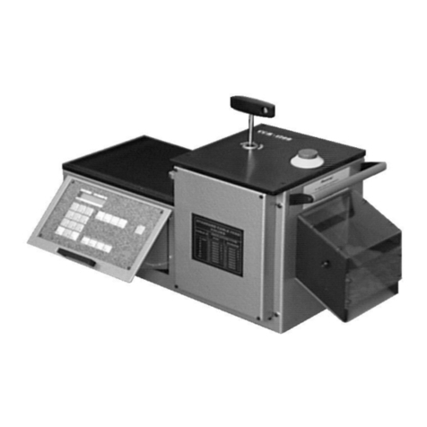
Schleuniger EcoCut 3300 User manual

EcoCut 3300
Automatic Cutting Machine
Reference Manual
Software Version 1.1x |Edition 4.0 (10-2013)

Address / distributors
2|108
Reference Manual |Edition 4.0 (10-2013) |
EcoCut 3300
Schleuniger AG
Bierigutstrasse 9
3608 Thun
Switzerland
P +41 (0)33 334 03 33
F +41 (0)33 334 03 34
www.schleuniger.com
Schleuniger AG
Geschäftsbereich Solutions
Gewerbestrasse 14
6314 Unteraegeri
Switzerland
P +41 (0)41 754 53 53
F +41 (0)41 754 53 50
www.schleuniger.ch
Schleuniger GmbH
Raiffeisenstrasse 14
42477 Radevormwald
Germany
P +49 (0)21 959 29-0
F +49 (0)21 959 29-105
www.schleuniger.com
Schleuniger, Inc.
87 Colin Drive
Manchester, NH 03103
USA
P +1 (603) 668 81 17
F +1 (603) 668 81 19
www.schleuniger-na.com
Schleuniger Japan Co., Ltd.
4-5-8, Tokai, Ota-ku
Tokyo 143-0001
Japan
P +81 (0)3 57 55 80 41
F +81 (0)3 57 55 80 45
www.schleuniger.co.jp
Schleuniger Trading (Shanghai) Co., Ltd.
108, BH Center
7755 Zhongchun Rd
Shanghai, 201101
China
P +86 (21) 62 52 66 77
F +86 (21) 62 40 86 55
www.schleuniger.cn
© 2013 Schleuniger
EN | ID-0000000138-001
Part #:
Order #:

Table of contents
Reference Manual |Edition 4.0 (10-2013) |
EcoCut 3300 3|108
TABLE OF CONTENTS
1GENERAL 9
1.1 MANUFACTURER .............................................................9
1.2 MANUFACTURING DATE / PRODUCT TYPE ........................................9
1.3 INFORMATION ABOUT THE OPERATOR'S HANDBOOK ..............................9
1.3.1 Contents of the manual........................................................... 9
1.3.2 Depository................................................................... 10
1.3.3 Responsibilities................................................................ 10
1.4 GENERAL SYMBOLS AND LEGEND ..............................................10
1.4.1 References and hints............................................................ 10
1.4.2 Legend......................................................................11
1.5 DECLARATION OF CONFORMITY ...............................................11
1.6 LIMITATION OF LIABILITY ..................................................... 11
1.7 WARRANTY STATEMENTS AND POLICIES ........................................11
1.8 COPYRIGHT PROTECTION .....................................................11
1.8.1 Trademarks...................................................................11
1.9 SPARE PARTS ................................................................12
2SAFETY 13
2.1 WARNING NOTICES ..........................................................13
2.2 GENERAL SAFETY NOTES ......................................................13
2.3 SOURCES OF DANGER / RISKS ..................................................13
2.4 INTENDED USAGE OF PRODUCT ............................................... 14
2.5 SAFETY SYMBOLS ............................................................14
2.5.1 Safety symbols used in manual.....................................................14
2.5.2 Safety symbols on the product..................................................... 15
2.6 MODIFICATION AND RETROFITTING ............................................15
2.7 PERSONNEL QUALIFICATION ..................................................15
2.7.1 Personnel classification.......................................................... 15
2.8 PERSONAL PROTECTIVE EQUIPMENT ............................................15
2.8.1 Eye protection.................................................................16
2.8.2 Protective clothes.............................................................. 16
2.8.3 Safety shoes.................................................................. 16
2.8.4 Snood-type cap or safety cover.....................................................16
2.9 SAFETY INSTALLATIONS ......................................................16
3TRANSPORT / PACKAGING / STORAGE 17
3.1 TRANSPORT INSPECTION ......................................................17
3.2 UNPACKING / LOADING .......................................................17
3.3 PACKAGING .................................................................17
3.3.1 The packaging.................................................................17
3.3.2 Handling packaging material...................................................... 17

Table of contents
4|108
Reference Manual |Edition 4.0 (10-2013) |
EcoCut 3300
3.4 INTERNAL TRANSPORTATION ..................................................18
3.5 STORAGE ...................................................................18
4PRODUCT SPECIFICATIONS 19
4.1 DIMENSIONS / WEIGHT .......................................................19
4.2 TECHNICAL SPECIFICATIONS .................................................. 19
4.3 REQUIREMENTS ON THE INSTALLATION LOCATION ...............................20
4.4 RATING PLATE ...............................................................20
5PRODUCT DESCRIPTION 23
5.1 CONCEPT ...................................................................23
5.2 FRONT ELEMENTS ............................................................23
5.2.1 Operator panel................................................................ 24
5.2.2 Gap setting wheel.............................................................. 24
5.2.3 Display of gap setup............................................................ 24
5.2.4 Setting knob for ejection chute.....................................................24
5.2.5 Wire end switch................................................................24
5.2.6 Wire end switch lift............................................................. 24
5.2.7 Wire entry guide............................................................... 24
5.2.8 Roller lever................................................................... 24
5.3 REAR / CONNECTORS .........................................................24
5.3.1 Postfeed interface (PPI, option).....................................................25
5.3.2 RS 232 interface................................................................25
5.3.3 HS/PF (HotStamp/Prefeeder) interface................................................25
5.3.4 Pedal connector............................................................... 26
5.3.5 Rating plate...................................................................26
5.3.6 Power connection.............................................................. 26
5.3.7 Main power switch..............................................................26
5.3.8 Fuse holder...................................................................26
5.4 DANGEROUS ZONES ON THE MACHINE .........................................26
5.4.1 Safety marking................................................................ 27
5.4.2 Danger zones operating area...................................................... 27
5.4.3 Danger zones rear.............................................................. 28
6INSTALLATION / FIRST COMMISSIONING 29
6.1 SAFETY INSTRUCTIONS .......................................................29
6.2 SAFETY APPLIANCES .........................................................29
6.3 POSITIONING / PUTTING INTO OPERATION ......................................29
6.3.1 Unpacking and setting up........................................................ 29
6.3.2 Setting the measuring unit and the menu language......................................30
6.3.3 Connecting compressed air (option).................................................30
7GENERAL HANDLING / OPERATION 31
7.1 GENERAL TOPICS FOR THE OPERATION .........................................31
7.2 SWITCHING ON ..............................................................31
7.3 SWITCH OFF ................................................................ 31

Table of contents
Reference Manual |Edition 4.0 (10-2013) |
EcoCut 3300 5|108
7.4 SETUP ......................................................................31
7.4.1 Loading wire..................................................................31
7.4.2 Producing a wire............................................................... 32
7.5 CHANGING THE ENTRY GUIDE .................................................32
7.6 WORK TO BE DONE AFTER OPERATION ..........................................34
7.6.1 General maintenance............................................................34
7.6.2 Additional maintenance work......................................................34
8OPERATION OF THE CONTROL SOFTWARE 35
8.1 OVERVIEW OPERATOR PANEL ..................................................35
8.1.1 Display...................................................................... 35
8.1.2 Keyboard.................................................................... 36
8.2 GENERAL ...................................................................37
8.2.1 Menu structure................................................................ 38
8.2.2 Input area....................................................................38
8.2.3 Entry fields................................................................... 39
8.3 MAIN MENU .................................................................39
8.4 WIRE SCREENS ...............................................................39
8.4.1 Wire data 1................................................................... 40
8.4.2 Wire data 2................................................................... 40
8.4.3 Wire marking..................................................................41
8.4.4 Wire stacker (PPI, option)......................................................... 42
8.4.5 Cable coiler (PPI, option)..........................................................42
8.5 FILE MENU ..................................................................42
8.5.1 New........................................................................ 43
8.5.2 Load........................................................................43
8.5.3 Save........................................................................44
8.5.4 Save as...................................................................... 44
8.6 CONFIGURATION ............................................................44
8.6.1 Devices......................................................................45
8.6.2 User........................................................................ 47
8.7 DIAGNOSTICS ...............................................................47
8.7.1 Info.........................................................................48
8.7.2 Machine..................................................................... 48
8.7.3 Peripheral....................................................................49
8.8 PASSWORD RESTRICTION .....................................................50
8.8.1 User level selection............................................................. 51
8.8.2 Change password.............................................................. 51
8.8.3 Password on/off................................................................51
8.8.4 Reset password................................................................52
8.8.5 Access rights..................................................................52
9OPERATION USING A MARKING DEVICE 53
9.1 INFORMATION FOR WIRE MARKING .............................................53
9.2 INSTALLING THE WIRE MARKER UNIT ...........................................53
9.2.1 Determining the distance.........................................................53

Table of contents
6|108
Reference Manual |Edition 4.0 (10-2013) |
EcoCut 3300
10 DIAGNOSTICS / TROUBLESHOOTING 55
10.1 GENERAL FAULT LOCALIZATION ...............................................55
10.1.1 Safety instructions..............................................................55
10.1.2 Behavior in case of an error........................................................55
10.2 FAULT INDICATORS ..........................................................55
10.3 DRAWINGS / CIRCUIT DIAGRAMS / FLOW CHARTS ................................55
10.4 ERROR MESSAGES ............................................................55
10.5 WARNINGS ..................................................................57
10.6 ACTIONS AFTER SOLVING ERRORS ..............................................58
11 MAINTENANCE / MAINTENANCE SCHEDULE 59
11.1 SAFETY INSTRUCTIONS .......................................................59
11.1.1 Personal protective equipment.....................................................59
11.2 CUSTOMER SERVICE ..........................................................59
11.2.1 Hotline...................................................................... 59
11.2.2 Behavior in case of an error........................................................59
11.3 CLASSIFICATION .............................................................59
11.3.1 Access rights..................................................................59
11.4 MAINTENANCE SCHEDULE ....................................................59
11.4.1 General......................................................................60
11.4.2 Maintenance chart..............................................................60
11.5 CIRCUIT DIAGRAMS, DRAWINGS, SPARE PART LISTS ...............................60
11.6 SPECIFICATION OF SPARE PARTS ...............................................60
11.7 GENERAL MAINTENANCE WORK ............................................... 60
11.7.1 General maintenance............................................................61
11.8 SETTINGS ...................................................................61
11.8.1 Adjusting blades............................................................... 61
11.8.2 Configuring the machine......................................................... 63
11.8.3 Setting back to factory default..................................................... 63
11.9 MAINTENANCE / REPAIR WORK ................................................64
11.9.1 General / safety................................................................64
11.9.2 Opening the housing............................................................65
11.9.3 Replacing blades...............................................................66
11.9.4 Replacing motors...............................................................67
11.9.5 Replacing belts................................................................ 69
11.9.6 Replacing feed rollers............................................................70
11.9.7 Exchanging mains fuses..........................................................73
12 SPARE PARTS / EXPLODED VIEW DRAWINGS 73
13 DECOMMISSIONING / DISPOSAL 75
13.1 DECOMMISSIONING ..........................................................75
13.2 DISASSEMBLY / DISPOSAL .....................................................75

Table of contents
Reference Manual |Edition 4.0 (10-2013) |
EcoCut 3300 7|108
14 APPENDIX 77
14.1 SOFTWARE UPGRADE ........................................................ 77
14.1.1 Installing Iguana ...............................................................77
14.1.2 Downloading upgrade file........................................................ 77
14.1.3 Upgrade procedure.............................................................78
14.2 CONNECTOR HS / PF ......................................................... 79
14.2.1 For use with a PreFeeder......................................................... 79
14.2.2 For use with a HotStamp......................................................... 80
14.3 PRE-/POSTFEED INTERFACE (PPI, OPTION) .......................................81
14.3.1 POSTFEED interface.............................................................82
14.4 BLOCK DIAGRAM ............................................................90
14.5 LUBRICATING GREASE MICROLUBE GBU-Y 131 ...................................91
INDEX 105

Table of contents
8|108
Reference Manual |Edition 4.0 (10-2013) |
EcoCut 3300

1. General
Reference Manual |Edition 4.0 (10-2013) |
EcoCut 3300 9|108
GENERAL
Thank you for your trust in the Schleuniger technique! You have acquired a high performance Schleuniger
product, designed and manufactured in our factory to your needs. Read through this manual with due
care and attention. It contains important tips and safety instructions, which allow precise and reliable
wire/cable production.
1.1
MANUFACTURER
In this Manual, Schleuniger AG Thun, Switzerland is referred to as manufacturer and abbreviated with
„Schleuniger“.
Schleuniger AG Phone: +41 (0)33 334 03 33
Bierigutstrasse 9 Fax: +41 (0)33 334 03 34
Switzerland Web: http://www.schleuniger.com
1.2
MANUFACTURING DATE / PRODUCT TYPE
See “EG-Declaration of Conformity (Register 2)“ of the ring binder.
1.3
INFORMATION ABOUT THE OPERATOR'S HANDBOOK
▄
The Operator's Handbook is part of the product and contains all the relevant information necessary to
operate the product efficiently and safely as intended.
▄
The mentioned safety notes and directions and as for the application field valid local accident preven-
tion regulations and general safety regulations must be complied.
▄
If the product changes hands, the Operator's Handbook must be supplied to the new owner.
▄
Make sure to update any relevant safety changes and corrections to the Operator's Handbook which
are available. Ask your local Schleuniger distributor for updates.
1.3.1
Contents of the manual
General
Each person using the product must be properly trained and have read and understood the Operator's
Handbook. This is also imperative, even when the respective person has operated such a product or simi-
lar previously and where they have been trained by the manufacturer.
The Operator's Handbook is no longer valid, if any of its contents (except a Quick Start Card, where availa-
ble) are removed or is changed on the data storage medium.
As Operator's Handbook we declare:
▄
In printed form the entire content of the folder according to the contents table.
▄
In electronic form, this „Reference Manual“, and the document „Parts Catalog“.
Construction
We are trying to make the operation of our products as easy as possible. To achieve this we have devel-
oped a concept for the Operator's Handbook.
The Operator's Handbook consists of at least three parts:

1. General
10|108
Reference Manual |Edition 4.0 (10-2013) |
EcoCut 3300
Quick Start Card (optional)
The Quick Start Card is available as a quick reference to take out of the ring binder. It is meant for the user
(operator), which is operating the product daily. See chapter "2.7.1 Personnel classification (Page 15)".
Reference Manual
A detailed description for the product and all options with full explanation of all functions available and
the maintenance. The Reference Manual is meant for the beginner as well as for the experienced user
(qualified personnel) as a learning- and reference guide. See chapter "2.7.1 Personnel classification
(Page 15)".
Parts catalog
A manual with the most important components of the product including the available options and the
wear parts. This part of the Operator's Handbook is intended mainly for the technical specialist. See chap-
ter "2.7.1 Personnel classification (Page 15)".
1.3.2
Depository
The Operator's Handbook must be available to the operating personnel at all times. Keep the Operator's
Handbook in such a way that it will not become damaged, so that the contents will remain clearly legible
beyond the expected lifespan of the product.
1.3.3
Responsibilities
▄
This Operator's Handbook must be kept near the product. It must be available to the operating per-
sonnel at all time.
▄
Always follow the instructions in this Operator's Handbook fully and without restraint.
1.4
GENERAL SYMBOLS AND LEGEND
1.4.1
References and hints
The listed pictograms have the following meaning in the Operator's Handbook:
Tip:
Application note and other useful infor-
mation which improves the intended uti-
lization of the product.
Info:
Information which helps to operate the
product efficiently and error-free.
Magnifier:
Overview diagram, introduction chapter.
1-2-3
Menu level:
Sub-screen with indication of the screen
level (viewed from main menu).
Procedure:
Important activity direction, program-
ming example.
3
Figure reference:
Referencing of text to picture elements in a
previous figure.
Topic:
Important safety relevant reference.
Disposal:
Waste that must be recycled and not be
disposed of with household waste.

1. General
Reference Manual |Edition 4.0 (10-2013) |
EcoCut 3300 11|108
1.4.2
Legend
Key, button, pictogram Commands and operating areas on the screen are in the text shown in bold,
squared brackets and capital letters [KEY].
Screen title/menu Screen titles and menu names are represented in the text in "inverted com-
mas".
Electric signal name Signal names are marked in capital letters and in "INVERTED COMMAS".
Cross referencing Cross referencing is indicated in the text in color and italics, e. g. see chapter
"1.4.2 Legend (Page 11)".
Activity direction Activity direction (installation procedure, programming example and others)
requests the user of the product to take an action. The activity direction is
marked with a digit and an arrow „1»“.
Consequence of an
activity direction Descriptions and affected actions in activity directions are marked with the
prefix „➥“.
Measure Measures in the manuals are given in millimeters.
1.5
DECLARATION OF CONFORMITY
See document “EG-Declaration of Conformity (Register 2)“ of the ring binder.
1.6
LIMITATION OF LIABILITY
The content of these operating instructions was put together taking into consideration the current stand-
ards and guidelines according to the state of the technology and our many years of experience.
The manufacturer disclaims any liability for damages and accidents as a result of:
▄
Disregard of the instructions
▄
Disregard of warning notices
▄
Non-intended usage
1.7
WARRANTY STATEMENTS AND POLICIES
See Schleuniger document „General Conditions of Sale and Delivery”.
1.8
COPYRIGHT PROTECTION
Keep this Operator's Handbook confidentially. It is intended for the exclusive use of persons operating the
product. Without written agreement, this manual shall not be made available to third parties.
The content of the Operator's Handbook in the form of text, illustrations, drawings, circuit diagrams or
other presentation, is protected by copyright law of the manufacturer.
1.8.1
Trademarks
Cayman™ and Iguana™ are trademarks of Schleuniger.
Windows® (XP, Vista, 7 or CE) are registered trademarks of Microsoft Corporation in USA and other coun-
tries.
All other brands or product names are trademarks or registered trademarks of their owners.

1. General
12|108
Reference Manual |Edition 4.0 (10-2013) |
EcoCut 3300
Registered trademarks are not specially marked in these instructions. However, this does not mean that
they can be used freely.
For further information, see chapter "14 Appendix (Page 77)".
1.9
SPARE PARTS
Always order original spare parts from your local Schleuniger distributor.
Any modifications in design or function of the spare parts, in terms of ongoing product improvement, are
subject to change without prior notification.
CAUTION
Use of unverified spare parts!
Unverified or defective spare parts may lead to damage, malfunction or com-
plete failure of the product and may affect safety. Therefore, exclusive use of
original Schleuniger spare parts is imperative.

2. Safety
Reference Manual |Edition 4.0 (10-2013) |
EcoCut 3300 13|108
SAFETY
2.1
WARNING NOTICES
The warning notices in the entire Operator's Handbook are marked with the following symbols. They are
headed by a safety alert symbol and the warning word which represents the degree of endangerment.
To avoid any injuries or material damage it is essential that you read and fully understand these symbols.
DANGER
Warning notice „Danger”
This panel indicates a hazardous situation, which if not avoided, will result in
death or serious injury.
WARNING
Warning notice „Warning”
This panel indicates a hazardous situation, which if not avoided, could result in
death or serious injury.
CAUTION
Warning notice „Caution
This panel indicates a hazardous situation, which if not avoided, may result in
minor or moderate injury.
NOTICE
Warning notice „Property damage”
This panel indicates a hazardous situation, which if not avoided, can result in
damage to property.
2.2
GENERAL SAFETY NOTES
▄
The product must only be operated when in good working order and condition. It must be checked
for intactness prior to the start of operation.
▄
Never operate the product in an explosive or flammable environment.
▄
Only operate the product in a dry, dust-free environment.
▄
Before performing any maintenance or repair work, unplug the machine from the mains and/or from
the air pressure supply.
▄
Never operate the product without connecting the earth conductor.
▄
Only use original Schleuniger equipment, especially interface connection cables (electromagnetic
compatibility).
▄
The product must always be operated through the Schleuniger emergency stop link unit, if it works
together with peripheral devices in a production line. Only then can a safe interruption of the com-
plete production line during an emergency be guaranteed.
▄
Any lubricating grease supplied with the machine, may only be used according to the instructions
given in this manual.
2.3
SOURCES OF DANGER / RISKS
With the use of technical products are dangers associated.

2. Safety
14|108
Reference Manual |Edition 4.0 (10-2013) |
EcoCut 3300
Dangers that could not be eliminated by design measures and also not by protection devices are residual
risks. The safety instructions in this Operator's Handbook refer to the known residual risks. Should be
shown additional operational risks, the operator is obliged to inform Schleuniger immediately.
However, the following risks remain:
▄
Inadequate maintenance can cause injury to the operator personnel and malfunction on the product.
▄
When working with a production line (PreFeeder, CableCoiler, WireStacker), in the wire/cable area by
catching body parts and clothing. Always close off these areas!
▄
On the wire/cable exit, wires/cables are ejected with high speed. There is a danger of stab wound and
concussion injury. Always close off this area!
▄
Risk of wire/cable blocking. Tensile forces can move to overturn machine, peripheral or bobbin and
injure the operator personnel.
▄
The product may come down the working table due to vibration and injure the operator personnel.
▄
A free standing panel may fall due to vibration and injure the operator.
▄
Tripping, falling, slipping due to connection cables, wire residue and air hoses lying around.
▄
Risk of increased noise levels while working with multiple machines in the room. Arrange for noise
control measures!
▄
Wires/cables may contain talc which can strain the work environment during wire/cable processing.
▄
By working with insufficient illumination in the workplace can cause injury.
2.4
INTENDED USAGE OF PRODUCT
WARNING
Only use the product according to the intended usage!
Any use of the product, which contradicts the intended use, is regarded as non-intended use. Schleunig-
er is not liable for any damages resulting from a non-intended use.
WARNING
Caution, risk of injury, property damage!
It is designed and manufactured exclusively for the following intended application:
The EcoCut 3300 must be used only for cutting of cables, wires and tubes within the given range accord-
ing to the technical specifications.
Disregarding may lead to injury of the operator personnel and to property damage.
2.5
SAFETY SYMBOLS
2.5.1
Safety symbols used in manual
In this manual, safety symbols are used which alert the user to potential hazards. They will be described
here in detail.
General Danger! Notes and instructions with this safety symbol should be followed
strictly. Disregarding may lead to injury and damage to the
machine.

2. Safety
Reference Manual |Edition 4.0 (10-2013) |
EcoCut 3300 15|108
Electric current! There is a danger of electric shock by contact with parts inside the
machine and on the mains socket. Therefore before opening the
machine always switch off the main switch and unplug it from the
mains. Touching electric components can cause injury to the oper-
ator personnel.
2.5.2
Safety symbols on the product
On the product, safety symbols are attached which alert the user to potential hazards. An overview where
this stickers are attached to, can be found in chapter "5 Product description (Page 23)".
2.6
MODIFICATION AND RETROFITTING
To avoid any dangerous situations and for an optimal performance, it is not allowed to make any modifi-
cations to, or retrofitting of the product, without explicit written permission of the manufacturer or the
local Schleuniger distributor. Standard options and accessories supplied by Schleuniger are excepted.
2.7
PERSONNEL QUALIFICATION
The individual tasks may only be performed by persons listed in the respective chapter.
The product is intended to be operated by personnel older than 14 years. It is strictly forbidden to grant
access to younger person.
WARNING
Risk of injury if operated by unqualified personnel!
Improper handling of the machine may lead to serious injury to personnel and
damage to the property.
2.7.1
Personnel classification
The following classifications in these instructions are specified for the individual activities.
Operating company
As a parent entity that is responsible for the proper use of the product and for the training and the com-
mitment of authorized persons. It defines the mandatory competencies for its operation and authority of
the authorized personnel.
Technical specialists
Due to product-specific training and mechanical and electrical skill and experience, are qualified to per-
form maintenance and repair work on the product.
Qualified personnel
Due to product-specific training, technical skill and work experience are qualified to install the software,
to put the product into operation and to instruct the operating personnel.
Operating personnel
Is a person who has been trained and authorized by the management to operate the product safely
according to the instructions. They have the ability to identify all sorts of danger and to avoid it. This
includes an adequate knowledge of accident prevention and first aid procedures.
Third party
Externally called in personnel of the operating company, service technicians and staff from Schleuniger.

2. Safety
16|108
Reference Manual |Edition 4.0 (10-2013) |
EcoCut 3300
2.8
PERSONAL PROTECTIVE EQUIPMENT
While working on the product, always wear protective equipment according to the local regulations to
minimize the risk of injury.
▄
Always wear protective equipment necessary for the work being carried out.
▄
Observe the safety markings for the protective equipment in the working area.
2.8.1
Eye protection
To protect the eyes from small particles produced during wire/cable stripping and cutting.
2.8.2
Protective clothes
Wear tight-fitting clothes with low tensile strength and no protruding parts. Protects from getting caught
up in moving machine parts.
2.8.3
Safety shoes
To protect from heavy, falling objects or reels.
2.8.4
Snood-type cap or safety cover
To protect long hair from getting caught up in moving machine parts.
2.9
SAFETY INSTALLATIONS
The built in safety interlocks on the machine (safety, protection, monitoring) must not be removed, by-
passed or changed. The safety circuits should be checked periodically. Defective safety equipments must
be fixed immediately before work may be continued.
▄
Never operate the machine without the safety hood.
▄
Never operate the machine if the safety cover is open.
▄
The emergency stop buttons must always be accessible.
▄
Do not remove any safety barriers.
▄
Do not break in the emergency stop link between the machine and the peripheral devices.

3. Transport / packaging / storage
Reference Manual |Edition 4.0 (10-2013) |
EcoCut 3300 17|108
TRANSPORT / PACKAGING / STORAGE
During unpacking, transportation or storage of the product always observe the following instructions.
They contain important information to avoid injury to the operator and property damage. Take into con-
sideration the weight of the machine during transportation and loading. See chapter "4.1 Dimensions /
weight (Page 19)".
NOTICE
Damage due to improper transportation!
Transportation by unqualified personnel may lead to extensive property dam-
age. Therefore:
▄
Handle with care and always observe the symbols and hints on the packag-
ing and the product when unloading and placing on site location.
▄
Only use the intended transportation accessories.
The instructions in this chapter must be carried out by qualified personnel!
3.1
TRANSPORT INSPECTION
Check the goods immediately after receiving for completeness and loss during shipment.
For loss on the packaging during shipment, proceed as follows:
▄
Do not accept the delivery or only with exceptions.
▄
Declare loss of shipment.
▄
Immediately report damages on the product.
NOTICE
Claim for damages!
Report any defective part immediately after it was identified. Claim for damages.
3.2
UNPACKING / LOADING
Take out the machine carefully from the package. Remove any transport lockers, binders and foam and
check for free moving of cylinders and drives (if available, read the packing instruction).
NOTICE
Remove the transport fixations!
Before use of the product, remove, if present, any marked transport fixations. For
later transportation store the transport fixations.
3.3
PACKAGING
3.3.1
The packaging
Store the packaging for later use on a weatherproof location.
3.3.2
Handling packaging material
Recycle the unneeded packaging.

3. Transport / packaging / storage
18|108
Reference Manual |Edition 4.0 (10-2013) |
EcoCut 3300
See chapter "13 Decommissioning / disposal (Page 75)".
3.4
INTERNAL TRANSPORTATION
As applicable, transport the product in the original packaging.
WARNING
Dislocation of packaging!
Danger from load dislocation. During transportation in a craft, the product may slip
off and cause serious material damage. Even the craft may start skidding, which
could result in an accident with incalculable consequences. Always secure the prod-
uct in the craft to prevent from slipping off.
3.5
STORAGE
Store the product under the following conditions:
▄
Not outdoor
▄
Observe temperature conditions
▄
Observe climatically conditions
See also chapter "4.2 Technical specifications (Page 19)".

4. Product specifications
Reference Manual |Edition 4.0 (10-2013) |
EcoCut 3300 19|108
PRODUCT SPECIFICATIONS
This chapter among others gives an overview of the important technical specifications of the product.
The technical data correspond to the theoretical values and achievable under normal conditions. Any
modifications in design or function, in terms of ongoing product improvement, are subject to change
without prior notification.
4.1
DIMENSIONS / WEIGHT
AB
C
Fig. 1: Dimensions
Description Value Unit
Weight (net) 22 kg
Measures Width (A) 270 mm
Length (B) 460 mm
Height (C) 270 mm
4.2
TECHNICAL SPECIFICATIONS
Description Value Unit
Limit values Wire diameter 12 mm
Wire width 100 mm
Conductor cross section
Stranded
Solid
16 (AWG 6)
6 (AWG 10)
mm2
Feed speed 1.6 m/s
Pulling force 110 N
Length resolution 0.1 mm

4. Product specifications
20|108
Reference Manual |Edition 4.0 (10-2013) |
EcoCut 3300
Description Value Unit
Mains connection Power connection 100/115
230/240 V
Line frequency 50/60 Hz
Power consumption 120 VA
Pressure range max. 7 bar
Noise emission Emission sound pressure level <70 dB(A)
Environment Temperature range 5-40 °C
Relative humidity, maximum 90 @ 20 °C
50 @ 40 °C %
Storage and transport temperature -25 to +55 °C
Interfaces Prefeeders and wire marker devices, RS 232
Optional: Pre-/Postfeed interface for synchron-
ized peripheral devices (PPI, option)
Options Air jet unit
Carbide blades
Quadruple wire guide
Wire guides to blades
Exit adapter for peripheral devices
Synchronized postfeed interface
External emergency stop button
Pedal
4.3
REQUIREMENTS ON THE INSTALLATION LOCATION
Place on a solid, level work floor. The machine is designed for handling on table height.
Table of contents
Other Schleuniger Cutter manuals