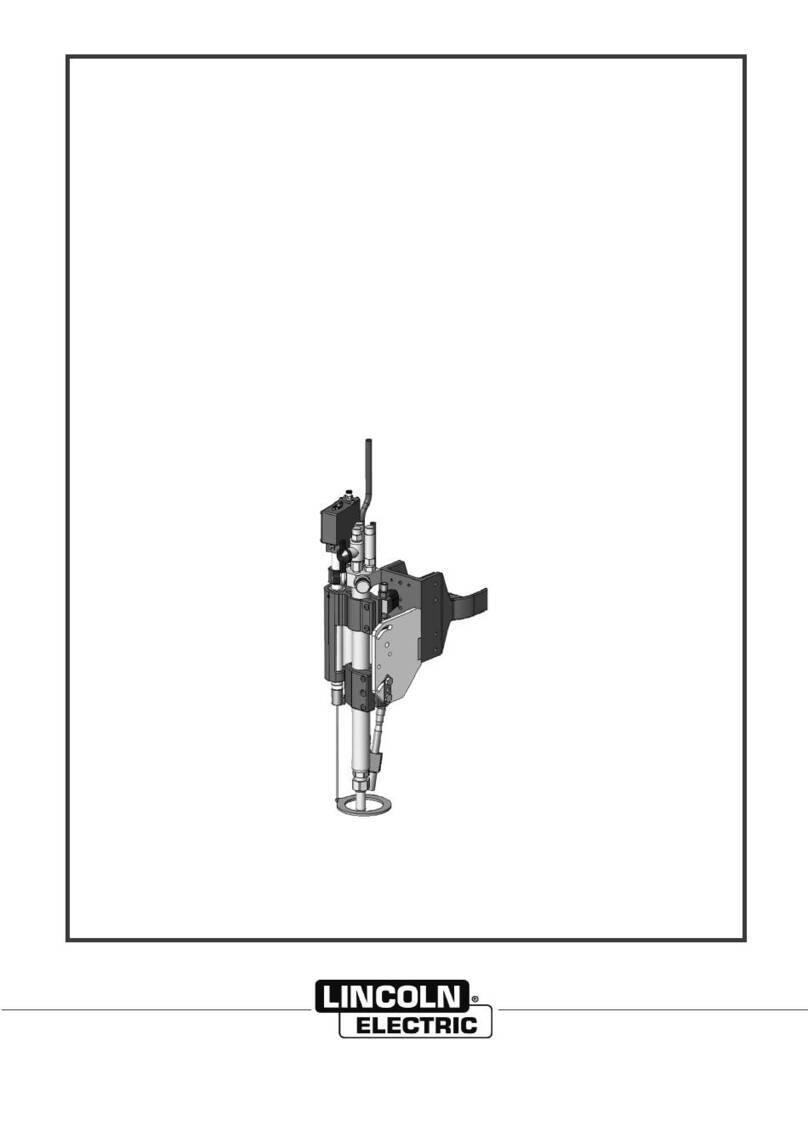
Lincoln Electric OPTITOME II Series Mounting instructions

CUTTING MACHINE
OPTITOME II
HPC II
SAFETY INSTRUCTIONS FOR USE AND MAINTENANCE
EDITION : EN Instructions for use REF : 8695 4788
REVISION : A
DATE : 11-2018 Original instructions

Thank you for the trust you have expressed by purchasing this equipment,
which will give you full satisfaction if you follow its instructions for use and
maintenance.
Its design, component specifications and workmanship comply with
applicable European directives.
Please refer to the enclosed CE declaration to identify the directives
applicable to it.
The manufacturer shall not be liable if the product is used in association with
items not recommended by the manufacturer.
For your safety, below is a non-limitative list of recommendations or
requirements, many of which appear in the labour code.
Lastly, please inform your supplier of any error you may find in this
instruction manual.

8695 4788
OPTITOME HPC 2 I
CONTENTS
A - IDENTIFICATION.........................................................................................................................1
B - SAFETY INSTRUCTIONS............................................................................................................2
1 - AIRBORNE NOISE .............................................................................................................2
2 - CONSIGNES PARTICULIERES DE SECURITE................................................................3
3 - LAYOUT..............................................................................................................................6
C - DESCRIPTION .............................................................................................................................8
1 - DESCRIPTION....................................................................................................................8
2 - GENERAL...........................................................................................................................9
3 - MECHANICAL ASSEMBLY................................................................................................10
4 - CUTTING TABLE................................................................................................................11
5 - TRANSVERSE CARRIAGE................................................................................................12
6 - POWER SYSTEMS ............................................................................................................12
7 - CONSOLE...........................................................................................................................13
8 - LIMIT OF SUPPLY..............................................................................................................14
D - ASSEMBLY AND INSTALLATION..............................................................................................15
1 - CONDITIONS OF INSTALLATION.....................................................................................15
2 - FLOOR PREPARATION.....................................................................................................16
3 - PUTTING IN PLACE OPTITOME 2040...............................................................................16
4 - PUTTING IN PLACE OPTITOME 1530...............................................................................23
5 - CONNECTING THE ENERGY SUPPLIES.........................................................................25
E - OPERATOR MANUAL.................................................................................................................27
1 - DESCRIPTION OF CONTROLS.........................................................................................27
2 - STARTING UP THE MACHINE..........................................................................................28
3 - STOPPING THE MACHINE................................................................................................30
F - MAINTENANCE............................................................................................................................31
1 - SERVICING.........................................................................................................................31
2 - TROUBLESHOOTING........................................................................................................33
3 - SPARE PARTS...................................................................................................................36
PERSONAL NOTES ..........................................................................................................................42

8695 4788
II OPTITOME HPC 2
INFORMATIONS
DISPLAYS AND PRESSURE GAUGES
The analogue and digital measuring devices or displays of voltage, current, speed, pressure, etc. are to be
considered as indicators
N°
MACHINE
07005030NG
OPTITOME HPC II 1530
07005010NG
OPTITOME HPC II 2010
07005040NG
OPTITOME HPC II 2040
07005060NG
OPTITOME HPC II 2060

8695 4788 / A
OPTITOME HPC 2 A-1
A - IDENTIFICATION
Quote this information in all correspondence.

8695 4788 / A
B-2 OPTITOME HPC 2
B - SAFETY INSTRUCTIONS
For general safety instructions, please refer to the specific manual supplied with the equipment « 8695 7050 ».
1 - AIRBORNE NOISE
Please refer to the specific manual supplied with the equipment.

8695 4788 / AB - SAFETY INSTRUCTIONS
OPTITOME HPC 2 B-3
2 - CONSIGNES PARTICULIERES DE SECURITE
HANDLING
For installation or maintenance operations, the operator must
use the lifting eyes provided for that purpose and shown on
the drawing.
CONDITIONS OF USE
No object is to be placed on the rolling tracks.
Do not climb on the cable drag chain.
Before handling sheets, make sure that the safety of persons
and property is protected.
Before using the machine, make sure that all the guards are in
place.
All guard covers must be screwed in.
Only authorised personnel may access electrical cabinets,
which must have locking systems.
No maintenance may be carried out on the machine when it is
supplied with power.
For any extended absence, the operator must shut off the
supply of utilities (electricity and fluids).
Before anyone starts working between the rolling tracks, make
sure that the power supply to the machine has been switched
off (locking an emergency stop button is sufficient).
Switch the power source off while changing the wearing parts
of the torch if the plasma process is being used.
STABILITY
The machine must be anchored to the floor.
"No climbing on the structure of the machine other than on
platforms or gangways designed for that purpose. To access
equipment at heights, the user must use accessing means in
accordance with the regulations, such as a safe mobile gangway,
lift basket etc".
Clean the working area from time to time.

B - SAFETY INSTRUCTIONS 8695 4788 / A
B-4 OPTITOME HPC 2
This machine may only be moved by its designer, namely LINCOLN
ELECTRIC.
Never modify the machine.
The machine is not designed for anchoring lifting equipment.
The use of Personal Protective Equipment (PPE) is mandatory.
Machine maintenance must be carried out with all the energy
supplies switched off.
The disconnection and padlocking of all energy sources is
mandatory.
The emergency stop and safety lines must be interlocked and tested
in accordance with the electricity diagram of the machine.
HANDLING OF PARTS
The equipment for handling workpieces that have been or
need to be cut is not part of the supply and is to be provided
by the customer. The customer must therefore take protective
measures appropriate for the equipment for handling the
workpieces.
IMPORTANT: While handling sheets to cut, take the
necessary precautions to avoid impacts on the machine and
the rolling tracks.
Impacts on any of the elements can lead to squareness faults
or the malfunctioning of the electrical shaft and therefore
incorrect cutting of the workpieces.
For safety reasons, the operator may not climb on the cutting
tables to handle the workpieces.
An accidental manoeuvre could restart the movement
unintentionally.
The machine must remain under the supervision of a trained
operator when it is operating.

8695 4788 / AB - SAFETY INSTRUCTIONS
OPTITOME HPC 2 B-5
IMPORTANT :
BEFORE ANY MAINTENANCE OPERATION, REMEMBER TO :
Switch off and lock out the electricity supply
Switch off, flush and lock out the gas and compressed air
supplies.
IMPORTANT! "Do not remove the Nylstop nuts from the
fastening screws of the guards: they keep them captive"

B - SAFETY INSTRUCTIONS 8695 4788 / A
B-6 OPTITOME HPC 2
For safety reasons, please apply the label supplied in this folder near the machine control console.
3 - LAYOUT
The operator station is located in front of the control console.
The machine you have purchased can be hazardous if you do not take certain
precautions for use.
Make sure that no part of the machine can come within less than 500 mm of an obstacle
according to the safety standards NF EN 349.
Important: the operator passage way must absolutely be clear over a minimum width of
800 mm according to safety standards NF EN 547-1-3.
The floor should be marked out as shown in the enclosed drawing.
While accessing the marked area, any person could be hit by the machine or the cable
drag chain.
See layout drawing supplied

8695 4788 / AB - SAFETY INSTRUCTIONS
OPTITOME HPC 2 B-7

8695 4788 / A
C-8 OPTITOME HPC 2
C - DESCRIPTION
1 - DESCRIPTION
1
Beam
2
Cutting table with guide rails
3
Tool carriage
4
Control panel
5
CNC control
6
Electrical power system
7
Tool holder

8695 4788 / AC - DESCRIPTION
OPTITOME HPC 2 C-9
2 - GENERAL
This is a numerically controlled single-piece plasma cutting machine that is particularly
suited to industries that use steel, stainless steel and aluminium for plates measuring :
1500*3000 => OPTITOME II 1530
2000*4000 => OPTITOME II 2040
2000*1000 => OPTITOME II 2010
2000*6000 => OPTITOME II 2060
The main intended applications are those of iron workers, metal workers, air
processing, air-conditioning, ventilation, refractory industries, workshops producing in
small and medium runs or support production.
It is managed by a CNC control of the type HPC DIGITAL PROCESS HPi.
This machine uses:
all the dry plasma cutting methods of the installations NERTAJET HP150
(150A) and HP300 (300A),
optional oxycutting to allow the occasional cutting of black steels, maximum
thickness 50mm,
optional WEN marking or FELT marking.
The control console supports the operating approach.
The integration of an extraction table (included in the basic offer) that can be
connected to any extraction and/or filtration system and fitted with slag collector boxes
makes its conditions of use maximally safe and healthy. The plate frame is removable,
giving easy access for cleaning the boxes, or for replacing it to make it easier to load
and unload cut pieces.
The frame is 800mm high and has been designed to allow access so that the distance
between the edge of the rails and the side ends of the table is as short as possible.

C - DESCRIPTION 8695 4788 / A
C-10 OPTITOME HPC 2
3 - MECHANICAL ASSEMBLY

8695 4788 / AC - DESCRIPTION
OPTITOME HPC 2 C-11
Size
A (mm)
B (mm)
C (mm)
D (mm)
1530
2550
4375
1500
3000
2010
3050
2550
2000
1000
2040
3050
5325
2000
4000
2060
3050
7380
2000
6000
This is a single-piece machine made up of a mechanically welded cutting table, with,
on each side, a guide rail with ball slides and a rack to guide and move the beam
Two guide rails with ball slides and a rack are fixed to the beam, to guide and move
the tool carriage
The high feed speed is 15m/min
A console cabinet to be fastened to the floor contains all the electrical and electronic
equipment that is required for control and operator dialogue
4 - CUTTING TABLE
This is a mechanically welded box that is fixed to the floor between the machine
frame, and which has a 350 outlet for connection to an extraction system. For this
table, we recommend the use of extraction with filtration that is suited to machine
performance.
A removable support frame for the piece to cut, made of sheet metal for plasma
cutting, is placed on the box.
The bottom contains slag collector boxes that are easily removable for cleaning.

C - DESCRIPTION 8695 4788 / A
C-12 OPTITOME HPC 2
5 - TRANSVERSE CARRIAGE
The carriage has three ball slides P1 for optimum guidance.
The powered carriage has the following functions:
Support for transverse power system
Support for one or more tools with option.
6 - POWER SYSTEMS
M1
Motor power BRUSHLESS « 750W 3000 rpm »
M2
Reduction gear, reduction 1/19.5
M3
M2 20-tooth pinion

8695 4788 / AC - DESCRIPTION
OPTITOME HPC 2 C-13
7 - CONSOLE
The control console of this range includes the CNC control HPC2 DIGITAL PROCESS HPi, with all the controls
required for starting up the machine and operating the cutting cycle.
This console is available in two versions :
Essential
Most controls are available only on the touchscreen.
Advanced
The most used commands are available on buttons on the front face for a better maneuverability of the
machine and the process.
Console Essential
Console Advanced

C - DESCRIPTION 8695 4788 / A
C-14 OPTITOME HPC 2
8 - LIMIT OF SUPPLY
The customer must supply and install a device for isolating each
source of energy (electricity, air, gas and water). The devices must be
clearly identified. They must be of the locking type.

8695 4788 / A
OPTITOME HPC 2 D-15
D - ASSEMBLY AND INSTALLATION
1 - CONDITIONS OF INSTALLATION
THE LAYOUT OF THE INSTALLATION MUST COMPLY WITH SAFETY STANDARD NF EN 547 -1 -
3 TO ENSURE PERSONAL PROTECTION
THE FOLLOWING CONDITIONS MUST BE COMPLIED
WITH BEFORE INSTALLING THE EQUIPMENT
ELECTRICITY SUPPLY
see supply drawing provided
VERY IMPORTANT
The power cable (customer supply) must have a section suitable for the power rating of the installation.
The customer is responsible for protecting the power cable and the installation itself.
Such protection must be appropriate for the neutral point treatment of the electricity supply.
The information required for sizing the protection is provided on the identification plate of the
installation.
SUPPLY OF GAS
see supply drawing provided
PNEUMATIC SUPPLY
see supply drawing provided
The user must provide a source of compressed air with a regulator that can supply the required flow
and pressure. The air must be clean, de-oiled and degreased.
QUALITY CLASS: as per standard ISO 8573-1
Solid pollutant class
Class 3
Grain size 5m
Mass concentration
5mg/m3
Water class
Class 3
Maximum dew point under pressure –200C
Total oil class
Class 5
Concentration 25 mg/m3
ARRANGEMENT OF CABLES AND FLEXIBLE HOSES
The customer must provide the means to support and protect cables and
flexible pipes from mechanical, chemical or thermal damage from their
source up to the entrance to the cable drag chain and from the machine up
to the entrance to the control console.

D - ASSEMBLY AND INSTALLATION 8695 4788 / A
D-16 OPTITOME HPC 2
TOOLS REQUIRED FOR INSTALLING THE MACHINE ON THE SITE
- Level, accuracy 1/10 per metre
- Impact drill for concrete, for bit Ø16
- Decameter
- Chalk line
- Vacuum cleaner
- 24 mm open-ended spanner
- 24 mm ring spanner
2 - FLOOR PREPARATION
See layout drawing supplied
The floor does not need any particular preparation for installing the machine;
however, we recommend a concrete floor for the machine to be satisfactorily stable.
Concrete screed in a single stretch (200 mm thick) made at least 21 days before
(standard BAEL 91). The thickness of the screed and its reinforcement are given for
guidance, and must be verified depending on the characteristics of the floor.
Single concrete longitudinal member. 20 Mpa (350 kg/m³) concrete with metal
reinforcement.
Flatness over the entire site with additional travelling tracks ± 10 mm.
30 mm level difference of screed (5 mm/m max.).
3 - PUTTING IN PLACE OPTITOME 2040
The components of the installation may only be transported using the slinging points
provided, with appropriate slinging equipment.
Check the flatness of the floor with an optical level and identify the high point.
1) Installation of thee parts of the table,
1
Part 1
2
Part 2
3
Part 3
This manual suits for next models
9
Table of contents
Other Lincoln Electric Cutter manuals

Lincoln Electric
Lincoln Electric ESSENTIAL OXYCUTTING Mounting instructions

Lincoln Electric
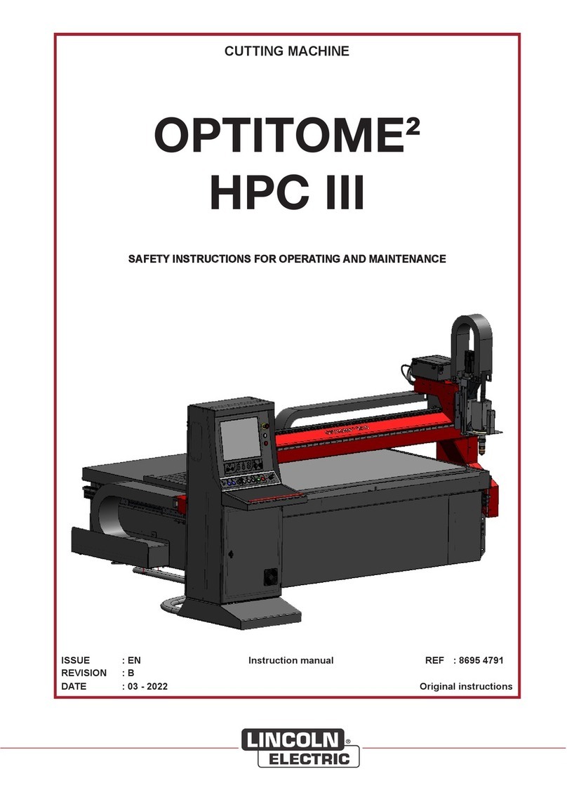
Lincoln Electric OPTITOME2 HPC III User manual

Lincoln Electric
Lincoln Electric Torchmate 5100 Series User manual

Lincoln Electric
Lincoln Electric MASTERPIPE Mini Profiler Operating instructions

Lincoln Electric
Lincoln Electric Torchmate 5100 Series User manual

Lincoln Electric
Lincoln Electric PRO-CUT 60 User manual

Lincoln Electric
Lincoln Electric Torchmate 4400 User manual

Lincoln Electric
Lincoln Electric Torchmate 5100 Series Operating instructions

Lincoln Electric
Lincoln Electric Growth Series User manual

Lincoln Electric
Lincoln Electric Torchmate 4400 User manual