DE - 4
1 Bestimmungsgemäße Verwendung ABICUT 25K/45/75
Richtwerte für Schneidfähigkeit
Die Angaben zur Schneidfähigkeit sind nur Richtwerte, da sie zusätzlich von
den nachfolgenden Punkten stark beeinflusst werden. Art und Qualität des
Materials; Druck und Unreinheiten der Druckluft; Temperatur des zu
schneidenden Werkstückes; der gewünschten Schnittqualität; Zustand von
Elektroden und Schneiddüse; Abstand und Stellung des Schneidbrenners zum
Werkstück; Stromquellen - Charakteristik; Schneidgeschwindigkeit.
ABICUT 25K ABICUT 45 ABICUT 75
Lichtbogenzünd- u.
Bemessungsspannung
---/7kV
Spannungsbemessung 500V Scheitelwert
Kühlart luft
Bemessung Steuereinrichtungen 42 VAC / 0,1-1 A
Tab. 2 Technische Daten
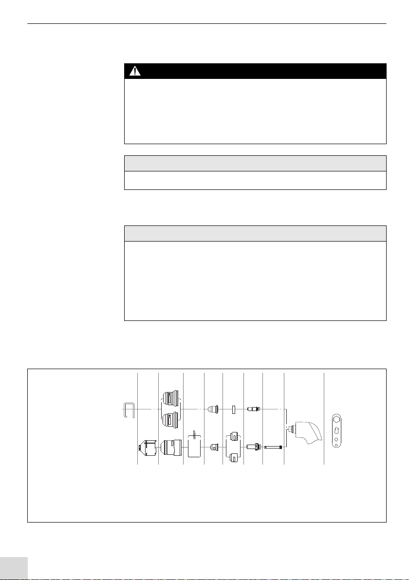
ABICUT 25K ABICUT 45 ABICUT 75
Düse Standard 0,65 mm / bis 20 A 0,65 mm / bis 25 A 1,0 mm / bis 55 A
Düse Standard 0,8 mm / bis 20 A 0,8 mm / bis 40 A 1,2 mm / bis 75 A
Düse lang 0,9 mm lang / bis 20 A 0,9 mm lang / bis 40 A 1,0 mm lang / bis 50 A
Düse lang 1,2 mm lang / bis 70 A
Tab. 3 Wahl der Plasmadüse
Materialstärke ABICUT 25K ABICUT 45 ABICUT 75
Stahl 6 mm bei 20 A 10 mm bei 40 A 20 mm bei 75 A
Edelstahl 6 mm bei 20 A 10 mm bei 40 A 18 mm bei 75 A
Aluminium 4 mm bei 20 A 6 mm bei 40 A 15 mm bei 75 A
Tab. 4 Richtwerte für Schneidfähigkeit
ABICUT 25K ABICUT 45 ABICUT 75
Standardlänge
(andere Längen möglich)
4m 6m 6m
Aufbau Schlauchpaket Schlauchpaket Schlauchpaket/
Koaxialkabel
Anschluss Strom/Luft-Kabel G1/4
Ausführung Einzelanschluss oder Zentralanschluss
Tab. 5 Schlauchpaket