Current Tools 77HRB User manual

77HRB
High Rise Base for Model 77 Series
Electric Benders
— Will also fit Greenlee®Model 555®C Benders*
CURRENT TOOLS • P. O. BOX 17026 GREENVILLE, SC 29606
800.230.5421 or 864.721.4230 • FAX 864.721.4232
www.currenttools.com
Operating, Safety and Parts Manual
11/2017
This manual is free of charge. All personnel who operate this high
rise base should have a copy of this manual and read and understand
its contents. To request a copy, call or write to the address below.
This manual should be read and understood by all personnel
who operate this high rise base. Failure to understand how to
safely operate this unit could result in injury or property damage.
This unit should only be operated by qualified personnel.
Model 77HRB
*Greenlee®and 555®are registered trademarks of Greenlee/Textron.
Shown with Current Tools Model 77SE Single Shoe Bender

2
TABLE OF CONTENTS
Important Safety Information ........................................................2
Model Description ...........................................................................2
Bender Mounting Instructions ....................................................3,4
Roller Support Instructions for 1 1⁄2" and 2" EMT or IMC............5
Linkage Arm Storage......................................................................6
Exploded View and Parts List ........................................................6
RETAIN SAFETY INFORMATION
IMPORTANT SAFETY INFORMATION
This manual should be read and understood by all personnel who operate
this high rise base. Failure to understand how to safely operate this unit
could result in injury or property damage. This unit should only be operated
by qualified personnel.
Follow ALL safety information provided by the manufacturer.
DO NOT stand on high rise base.
ONLY mount Current Tools Model 77 Electric Bender or
Greenlee®Model 555®C Bender to the high rise base.*
ALWAYS refer to manufacturers operating instruction manual
for proper operating instructions of the bender.
ONLY roll on a firm, flat, smooth surface.
ALWAYS make sure the bender is properly secured to the high
rise base before moving or operating the bender.
NEVER alter the high rise base.
ONLY use the forklift pockets to lift the high rise base.
ALWAYS lock the two swivel locking casters when operating
the bender.
MODEL DESCRIPTION
77HRB High Rise Base with mounting hardware for use with
Current Tools Model 77 Bender and Greenlee®
Model 555®C Bender.*
WARNING
DANGER
CAUTION
WARNING
DANGER
CAUTION
WARNING
DANGER
CAUTION
WARNING
DANGER
CAUTION
WARNING
DANGER
CAUTION
WARNING
DANGER
CAUTION
WARNING
DANGER
CAUTION
*Greenlee and 555 are registered trademarks of Greenlee/Textron.
WARNING
DANGER
CAUTION

BENDER MOUNTING INSTRUCTIONS
1. Install casters on the High Rise
Base. The two rigid casters mount
on the front of the frame and the
two swivel casters mount on the
rear of the frame (See Figure 3A).
2. Remove all bending shoes and
roller supports from the bender.
NOTE: Newer style Greenlee®555®C*
Benders may not have mounting
holes in the bottom pads of the
front legs. In order to mount
these units, holes will need to be
drilled. See Figure 3B for hole
size and location
3. Remove both wheels and the axle
from the bender.
4. Lock the swivel casters on the High
Rise Base.
5. Attach a strap rated for a minimum
of 500 lbs. around the front nose
of the bender as well as around
the rear shoe storage nose of the
bender (see photo 3).
6. Next, identify the shoe group you
will be using to determine the bender
mounting position. See Figure 3C for illustrations on the correct mounting
position of the bender for single shoe groups and multi-shoe groups. The
bender must be mounted in the correct position for all components to
operate properly.
Rear
Rigid
Front
Rigid
Swivel
Figure 3A
Photo 3
3
Multi Shoe
Group Bender
Leg Mounting
Position
Single Shoe
Group Bender Leg
Mounting Position
*Greenlee and 555 are registered trademarks of Greenlee/Textron.
Figure 3C
Center to
center of
holes on
bottom pads
1 3/8"
5/8" ø
19" Bender
front legs
Figure 3B

BENDER MOUNTING INSTRUCTIONS – continued
7. Place the bender onto the High Rise Base, lining up the mounting holes
on the bender with the correct mounting holes on the base. Install and
tighten the provided hardware as shown in Figure 4.
NOTE: For the single shoe mounting position (see Figure 3C and Figure 4),
an access hole is provided on the underside of the square tubing to allow
for tightening of the front leg hardware.
8. If desired, take the bender handle off the bender by removing the four
(4) bolts holding it onto the bender frame.
9. Re-install the bending shoe and roller support according to the
appropriate bender operating manual.
ALWAYS lock the two swivel locking casters when
operating the bender.
4
WARNING
DANGER
CAUTION
Figure 4
Access hole located on
underside of square tubing
to allow for tightening of
front leg hardware.
Item # Part # Qty. Description
1 77HRB-101 1 High Rise Base
2 77 1 Electric Bender
3 451-25 8 Washer
4 77-025 4 Screw – Hx Hd Cap
1/2-13 × 1 1/4"
5 281-15 4 Nut – Hex, 1/2-13
Thin Nylon Insert
Shown mounting the bender to the High Rise
Base for use with single shoe groups

ROLLER SUPPORT INSTRUCTIONS FOR 1 1/2"
AND 2" EMT OR IMC CONDUIT
5
1. Refer to the appropriate conduit bender manual for mounting instructions of the
shoe and roller support. Be sure to match the correct shoe with its corresponding
roller support and install on the bender.
2. Attach the roller support linkage connector to the “engaging pedal” on the roller
support. See drawing 5A for attaching the linkage connector to the Current Tools
roller support and drawing 5B for attaching the linkage connector to the Greenlee®
roller support.*
3. The foot pedal mounted on the 77HRB frame will now become the “engaging pedal”
to operate the roller support. With the roller support linkage attached, refer to the
bending instructions for 1 1/2" and 2" EMT or IMC conduit located in the appropriate
conduit bender manual.
Figure 5A
Figure 5B
*Greenlee is a registered trademark of Greenlee/Textron.
Linkage
Connector
1½" to 2"
EMT or IMC
Roller Support
(Greenlee®)
Connector Clamp
Engaging
Pedal
1½" to 2"
EMT or IMC
Roller Support
(Current Tools)
Engaging
Pedal
Linkage
Connector
Connector
Clamp
NOTE: The two screws that go through the connector clamp need to be tightened onto the Current Tools
engaging pedal. The third screw is only needed when mounting to a Greenlee®roller support.*
NOTE: All three screws on the linkage connector must be tightened onto the Greenlee®engaging pedal.*

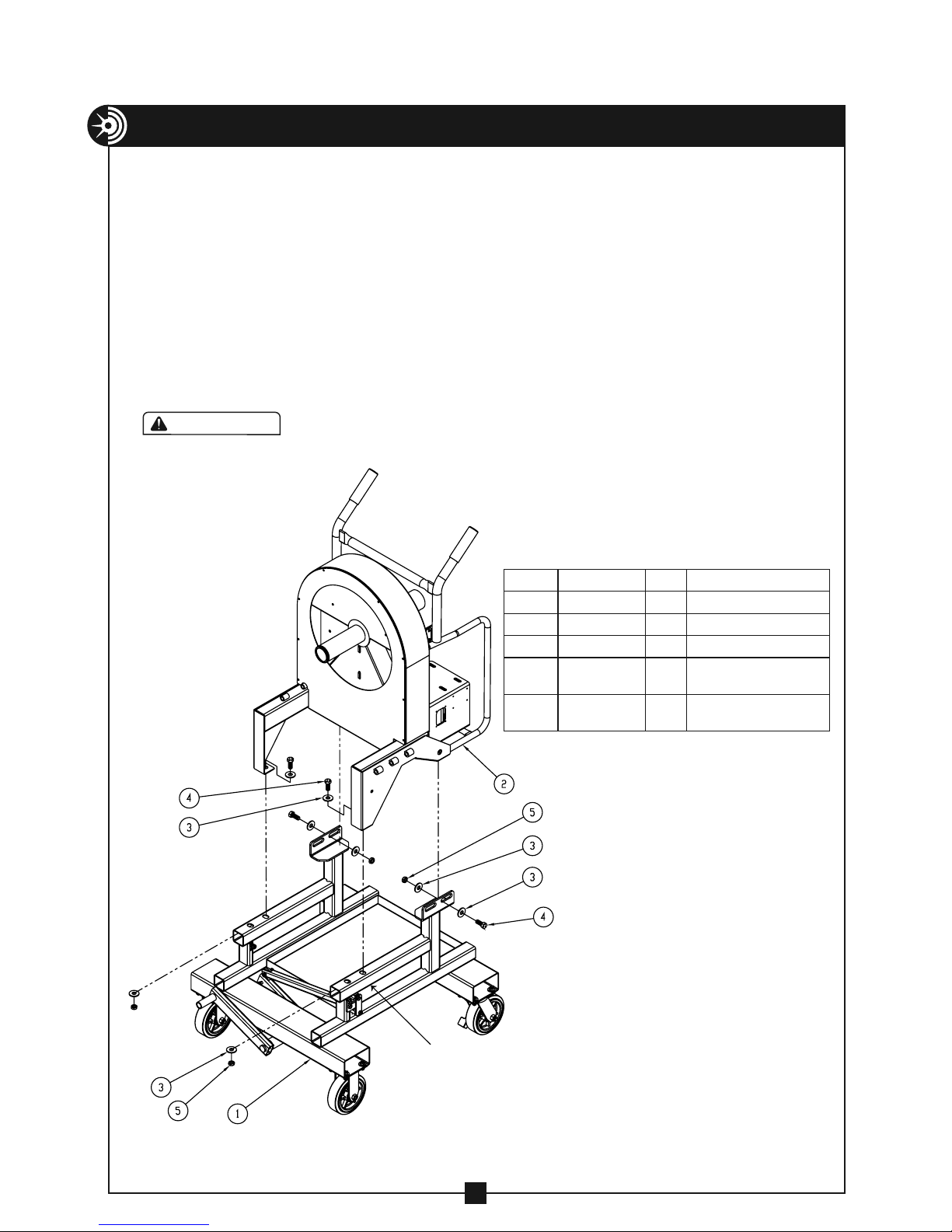
EXPLODED VIEW & PARTS LIST
6
ITEM# PART# QTY DESCRIPTION
1........ 2-1301-4...........1 ........ LOCKNUT, NYLON INSERT – 5/16-18
2........ 2-1501-4...........3 ........ LOCKNUT, NYLON INSERT – 3/8-16
3...........33-29 .............1........ SCREW, SKT. SHOULDER – 3/8" ×2"
4....... 77-002D1..........3........ SCREW, HX. HD. CAP – 5/16-18 ×3/4"
5...... 77HRB-001 ........1........ SCREW, SKT. SHOULDER – 3/8" ×3/4"
6...... 77HRB-002 ........1........ SCREW, SKT. SHOULDER – 3/8" ×1"
7...... 77HRB-005 ........3........ SCREW, HX. HD. CAP – 3/8-16 ×2 3/4"
8...... 77HRB-006 ........1........ SCREW, SKT. SHOULDER – 3/8-16 ×1/2"
9...... 77HRB-101 ........1........ BASE
10..... 77HRB-104 ........1........ LEVER – FOOT
11..... 77HRB-112 ........1........ CONNECTOR – LINKAGE
12..... 77HRB-119 ........1........ CLAMP – CONNECTOR
13..... 77HRB-126 ........1........ ARM – LINKAGE
14..... 77HRB-129 ........1........ ARM – LEVER
15..... 77HRB-130 ........1........ MOUNT – BRACKET
16.........452-27 ...........16 ....... WASHER, LOCK – 3/8"
17.........452-28 ...........16 ....... NUT, HEX – 3/8-16
18..........506-3 ............16 ....... WASHER, FLAT – 3/8"
19........513-001 ...........2........ CASTER – SWIVEL
20........513-002 ...........2........ CASTER – FIXED
21.........524-11 ...........16 ....... SCREW, HX. HD. CAP – 3/8"-16 ×1"
22.........610-25 ............2........ LOCKNUT, THIN NYLON INSERT – 3/8-16
23.........747-37 ............1........ SPRING
24.........812-14 ............2........ BUSHING
LINKAGE ARM STORAGE
When the roller support linkage arm
is not required, a storage bracket is
provided. See Figure 6 for linkage
arm storage illustration.
Figure 6
Linkage
Arm
Connector
Clamp
Table of contents
Other Current Tools Cutter manuals
Popular Cutter manuals by other brands

Logan Graphic Products
Logan Graphic Products 650-1 instruction manual

Hawksmoor
Hawksmoor CG330FHB ORIGINAL USER INSTRUCTIONS

Woods
Woods BRUSHBULL BB6000X Operator's manual

Daewoo
Daewoo DACNQ740S user manual

Feider Machines
Feider Machines F2000TM-A Original instructions

haupa
haupa AS6-40 instruction manual