Schlumbohm EndoPilot 2 User manual

610 2221 v07- 25.01.2021
EndoPilot²
User manual
Schlumbohm

Pilot²
- 2 -
Illustration 1 Control unit
Basic device
LED
1a
Right side of the device
1b
1c
1d
Rear side with microSD card
1e
1f
Left side of the device

Pilot²
Doc. No. 610 2221 v07 - 3 - (*applicable with the ultrasonic extension module)
Illustration 2 Illustration 3
Illustration 4 4a 4b 4c 4d 4e 4f
Illustration 4e
contact wire, housing, spring, threaded bush, knob, contact
You can dismantle the patented file clamp (4e) for reprocessing
(cleaning, disinfection and sterilization).
A universal key for ultrasonic-tools can be used as a tool for assembly
(with a wrench size of 3.2 mm).

Pilot²
- 4 -
Illustration 5
Illustration 6
Illustration 7 7a 7b
Illustration 8
Illustration 9 Ill.10 Ill.11 Illustration 12 12a 12d 12b
Illustration 13
12c
Illustration 14
Illustration 15a
Illustration 15b

Pilot²
Doc. No. 610 2221 v07 - 5 - (*applicable with the ultrasonic extension module)
Description of the single parts
ill.
Ref. No.
Designation
#
1 110 2011EndoPilot² Control unit with a touch screen, including 5
connecting sockets and a microSD slot (1a to 1f)
A2
2
109 2322
110 2203
Power supply with primary plug, 2 models available
Input: 100 – 240 V AC Output: 12 V DC 1.25 A
Input: 100 – 240 V AC Output: 12 V DC 1.50 A
A2
A2
3 109 2361 Wireless foot switch, single pedal with Bluetooth
A2
4
109 2311
109 2312
109 2314
109 2318
109 2315
109 2316
110 2303
Apex cable set (from version v06 on)
consisting of:
4a – Measuring cable with plug
4b – Lip-clip
4c – Cap for the plug socket (for Lip-clip)
4d – Cable for file clamp
4e – File clamp (can be dismantled)
The file clamp can be dismantled (see ill. 4e).
To dismantle, the contact is unscrewed and removed from
the knob. You can clean all parts individually (see
reprocessing instructions).
At the end of assembly, firmly tighten the contact again.
Caution: Check if the device is functioning properly! Loose
parts may fall out and enter the patient's mouth.
4f - Retainer for apex cable (mounted on the device)
A2
A1
A1
A1
A1
A1
5 109 0126
Contra-angle for apex measurement. Fully insulated,
1:1 gear, tools-coupling ISO 14457:2017 and
ISO-E motor coupling ISO 3964:2016 + Amd. 1:2018
A3
6 109 0112
Motor with apex measuring contact,
LED power indicator and
ISO-E motor coupling ISO 3964:2016 + Amd. 1:2018
A2
7
109 0151
540 5173
364 2901
DownPack (D-Pack) handpiece with LED indicator
for processing removable parts:
7a – Screw cap
7b – Blue O-ring
A2
A1
A1
8 109 0152
to ...56
D-Pack heating tips type E&Q standard Ø2,35mm
Available in 5 different sizes: XF, F, FM, M and ML
Accessories from Original manufacturer: Meta Biomed; Item:
EQ0036XF, EQ0023F, EQ0032FM, EQ0034M a. EQ0035ML
A4
12
9
823-810
823-616
BackFill gun (Order-no.110 1041)
12a - Release knob, 12b - Piston,
12c - Lever and 12d – Guide-Cylinder with rotary knob
Nut for BackFill-Needles (mounted on the back-fill gun)
A5
A5

Pilot²
- 6 -
ill.
Ref. No.
Designation
#
10
11
13
14
15a
15b
823-620
823-623
823-635
823-815
822-613
822-602
823-813
822-609
Accessories from original manufacturer:
Obtura Spartan / Young innovations
BackFill Needles 20 ga (5 pcs) (Order-no.110 1044)
Obtura Spartan
BackFill Needles 23 ga (5 pcs) (Order-no.110 1045)
Obtura Spartan
BackFill Needles 25 ga (5 pcs) (Order-no.110 1046)
Obtura Spartan
Thermal protector (4 pcs.) (Order-no.110 1043)
Heat insulator protects against thermal damage
Obtura Spartan
Obtura Multi Tool for shaping and for screwing on and
unscrewing the BackFill needles
Obtura Spartan
Not part of the Set :
Standard Gutta-percha pellets From the US market, see
Obtura Spartan; (box with 100 pcs.)
Obtura Cleaning brushes
(2 brushes) to clean the BackFill gun
Obtura Spartan
Obtura Cleaning Solution
Obtura Spartan
A5
A5
( - )
( - )
( - )
( - )
(#) refers to the relevant processing instructions A1-A5, see chapter 18
(-) means: The manufacturer has not foreseen any preparation for the product.

Pilot²
Doc. No. 610 2221 v07 - 7 - (*applicable with the ultrasonic extension module)
Ultrasonic module*
Illustration 16EndoPilot² with ultrasonic module
Description of the single parts
ill.
Ref. No
Designation
#
16 110 3201 Ultrasonic module with 1 connecting socket (15a)
A2
17 X12282 Ultrasonic handpiece with Satelec®compatible screw thread
Type: Acteon Satelec Suprasson (Order-no. 109 3102) A6
18 109 3132 Rinsing adapter Attachment to a standard syringe for flushing
the Acteon Satelec Suprasson handpiece A1
19 F00406 Wrench (Order-no. 109 3113)
Acteon Satelec universal wrench for ultrasonic tips A6
20 109 3122 Ultrasonic handpiece cable
Acteon Satelec highly flexible supply cable with plug A6
21 109 2351
Optional
Twin wireless foot switch
Pedal I = Start
Pedal II = Select / to select the functions,
including 2x 1.5 V batteries, type AA
A2
(#) refers to the relevant processing instructions A1-A6, see chapter 18

Pilot²
- 8 -
cable guide for
motor-, apex- and
ultrasonic-cable
(a locking clamp keeps
the cables in place)
Illustration 16a
Ultrasonic module
Bottom compartment with the connection for the ultrasonic cable
Illustration 17 Illustration 18 Illustration 19
Rinsing sleeve
(for cleaning)
Illustration 20 lllustration 21

Pilot²
Doc. No. 610 2221 v07 - 9 - (*applicable with the ultrasonic extension module)
Congratulations!
We are delighted you have decided to purchase the EndoPilot². You have made a good
choice. The family-owned company Schlumbohm®has been successful on the dental
industry market for 50 years. These many years of experience, as well as excellent contacts
to specialists, nationally and internationally, allow Schlumbohm®to design outstanding
devices that enable both the patient and the dentist to achieve an optimal treatment result.
In addition to striving, of course, for an optimal treatment result, the focus for each
development is on an easy and most convenient handling.
With EndoPilot², you have acquired a product which has been developed and tested with
the utmost care. The device meets the highest demands with regard to function and operation.
Caution! The device is available in various configuration levels
The EndoPilot² systems can be ordered in different configuration levels:
•EndoPilot ² comfort (REF 110 0607)
Endo motor with apex locator
•EndoPilot ² plus (REF 110 0609)
Endo motor with apex locator, DownPack and BackFill
•EndoPilot ² ultra: (REF 110 0610)
Endo motor with apex locator and ultrasonic extension
•EndoPilot ² ultra plus: (REF 110 0611)
Endo motor with apex locator, DownPack, BackFill, ultrasonic
This user manual describes the:
EndoPilot² comfort, EndoPilot² plus, EndoPilot² ultra and EndoPilot² ultra plus.
Devices with less function, as for example the model “EndoPilot² comfort” can be upgraded,
the device must be returned to the manufacturer.
All chapters for the “ultrasonic-function” are marked with: *
Manufacturer information:
Schlumbohm GmbH & Co. KG Phone: 011-49 - 4324 - 8929 - 0
Klein Floyen 8-10 Fax: 011-49 - 4324 - 8929 - 29
D-24616 Brokstedt post@schlumbohm.de
Germany www.schlumbohm.com
WEEE reg. no. DE 88116129
The manufacturer reserves the right to change the information and data contained in this
user manual without prior notice.
This user manual has been prepared with the greatest possible care. However, as errors can
never be fully excluded, we would appreciate any information at any time so we can improve
the documentation for you. Please contact us directly in such an event. Also, should you have
any further questions, please do not hesitate to contact us.

Pilot²
- 10 -
Table of contents......................................................................................................................... Page
1.1. Symbols used ........................................................................................................................... 11
1.2.Intended use ............................................................................................................................. 13
1.3. Device Description ................................................................................................................... 13
1.3.1. Apex locator ................................................................................................................ 13
1.3.2.Motor ........................................................................................................................... 13
1.3.3. DownPack hand-piece with heating tip ........................................................................ 13
1.3.4. BackFill gun................................................................................................................. 13
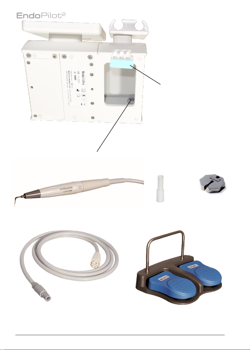
1.3.5. Ultrasonic handpiece*.................................................................................................. 13
1.4. General precautions................................................................................................................. 14
1.4.1. Contraindications......................................................................................................... 14
1.4.2. Operating instructions.................................................................................................. 14
2. First steps.................................................................................................................... 16
2.1. Assembly ................................................................................................................................... 16
2.2. Holders for the handpieces ..................................................................................................... 17
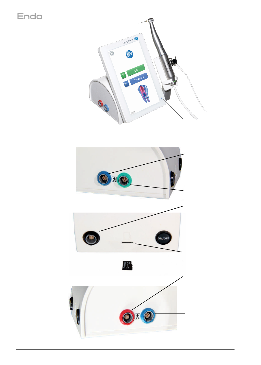
2.3. Connection ................................................................................................................................ 17
2.4. Touch display ............................................................................................................................ 18
2.5. Foot switch ................................................................................................................................ 18
2.6. Charging, switching-on, standby mode, switching-off ......................................................... 19
2.7. Preparation of the root canal - motor and contra-angle....................................................... 19
2.8. Filling technique - DownPack (D-Pack)................................................................................. 20
2.9. Filling technique - BackFill....................................................................................................... 21
3. Manual apex length determination ............................................................................... 22
3.1. Tips for length determination................................................................................................... 23
4. Motor system............................................................................................................... 24
4.1. Favorites .................................................................................................................................... 24
4.2. Selection of the file systems ................................................................................................... 24
4.3. Preparation................................................................................................................................ 25
4.4. MyFile file system..................................................................................................................... 25
4.5. Setup motor............................................................................................................................... 26
4.5.1. File data ...................................................................................................................... 26
4.5.2. Reciprocal function ...................................................................................................... 27
4.5.3. Apex functions during motor operation......................................................................... 28
4.5.4. Calibrate...................................................................................................................... 29
5. Obturation ................................................................................................................... 30
5.1. DownPack ................................................................................................................................. 30
5.2. BackFill ...................................................................................................................................... 30
6. Ultrasonic function*...................................................................................................... 31
6.1. Operating instructions* ............................................................................................................ 31
6.2. Setting the ultrasonic power output* ...................................................................................... 32
6.3. Ultrasonic instrument selection* ............................................................................................. 32
6.4. Setting the run time*................................................................................................................. 32
7. Software release and updates ..................................................................................... 33
8. Brightness / Volume..................................................................................................... 33
9. Setting the language.................................................................................................... 33
10. Auto-off time................................................................................................................ 33
11. Service information / Bluetooth .................................................................................... 33
12. Maintenance, transport and disposal ........................................................................... 34
12.1. Periodical tests ......................................................................................................................... 34
12.2. Maintenance.............................................................................................................................. 35
12.3. Transport ................................................................................................................................... 35
12.4. Disposal..................................................................................................................................... 36
13. Troubleshooting........................................................................................................... 37
14. Error messages ........................................................................................................... 39
15. Warranty / Liability ....................................................................................................... 39
16. Technical Data............................................................................................................. 40
17. EMC manufacturer's declaration.................................................................................. 41
18. Cleaning, disinfection sterilization (Processing) ......................................................... 44

Pilot²
Doc. No. 610 2221 v07 - 11 - (*applicable with the ultrasonic extension module)
1. Notes
1.1. Symbols used
Symbol Title, Description / Explanatory Text, Standard / Reference No. of Symbol
The product complies with the requirements of EU Regulations / No. of notified body
Caution
Indicates the need for the user to consult the instructions for use for important cautionary
information such as warnings and precautions that cannot, for a variety of reasons, be
presented on the medical device itself.
ISO 15223-1:2016 / Ref. 5.5.4
Type BF Applied Part
To identify a type BF applied part complying with IEC 60601-1
IEC 60601-1: 2005+Cor.:2006+Cor.:2007+A1:2012 / Ref. Table D1 / 20
Waste Collection
Separate collection for waste of electrical and electronic equipment.
EN 50419 - Marking of electrical and electronic equipment in accordance with article 11(2) of Directive
2002/96/EC
Do not re-use
Device intended for single use only and not to be re-used
ISO 15223-1:2016 / Ref. 5.4.2
Non-sterile
A medical device not subjected to sterilization
ISO 15223-1:2016 / Ref. 5.2.7
UDI of the device, Data-Matrix-Code (GS1-Code)
UL Component Recognition Mark
indicates compliance with Canadian and U.S. requirements
EU representative
EU authorised representative
ISO 15223-1:2016 / Ref. 5.1.2
automated processing in the thermal disinfector
Steam sterilization up to the indicated temperature
Batch Code
Batch code so the lot or batch can be identified
ISO 15223-1:2016 / Ref. 5
2021
Manufacturer/ Date of Manufacture
Indicates the medical device manufacturer /
Indicates Date of Manufacturer
ISO 15223-1:2016 / Ref. 5.5.1 /5.1.3

Pilot²
- 12 -
Description of the symbols used.
IP31
Ingress protection code
Protection against particles with 2.5 mm diameter and dripping water
complying with IEC 60601-1
IEC 60601-1: 2005+Cor.:2006+Cor.:2007+A1:2012 / Ref. Table D3 / 2
Catalogue Number
Indicates catalogue number, part number of device
ISO 15223-1:2016 / Ref. 5.1.6
Serial Number
Serial number so the device can be identified
ISO 15223-1:2016 / Ref. 5.1.7
Consult Instructions for Use
Indicates the need for user to refer to instructions for use
ISO 15223-1:2016 / Ref. 5.4.3
48 Wh
The device contains a lithium-ion battery (power output 48 Wh)
(The current shipping instructions must be followed during shipping!)
Class II equipment
To identify a class II insolation protection, complying with IEC 60601-1
IEC 60601-1: 2005+Cor.:2006+Cor.:2007+A1:2012 / Ref. Table D1 / 9
Consult Instructions for Use
Indicates the need for user to refer to instructions for use
IEC 60601-1: 2005+Cor.:2006+Cor.:2007+A1:2012 / Ref. Table D2 / 10
Wireless connection
Fragile, handle with care
Indicates a medical device that can be broken or damaged if not handled carefully.
ISO 15223-1:2016 / Ref. 5.3.1
Temperature Limit
Indicates temperature the medical device can be exposed
ISO 15223-1:2016 / Ref. 5.3.7
Different values on the outer package and on the device!
Package: Note temperature during storage / transport (-15°C to +60°C)
Device sticker: Note temperature during operation (+15°C to +40°C)
Keep Dry
Indicates a medical device that needs to be protected from moisture.
ISO 15223-1:2016 / Ref. 5.3.4
Humidity limitation
Relative humidity range for storage (on package) or use (on device)
ISO 15223-1:2016 / Ref. 5.3.8
This side up
ISO 7000:2008 / Ref. 0623
Medical Device
This item is a medical-device
ISO 15223-1 draft

Pilot²
Doc. No. 610 2221 v07 - 13 - (*applicable with the ultrasonic extension module)
Description of the symbols used.
Prescription Use Only
Caution: Federal (U.S.) law restricts this device to sale by or on the order of a physician.
No standard; designated by FDA per 21 CFR 801.109(b)(1)
Temperature Limit
Indicates the temperature limits to which the medical device can be safely exposed.
for storage (on package) or use (on device)
ISO 15223-1:2016 / Ref. 5.3.7 (the values in this listing are examples)
1.2. Intended use
The EndoPilot² systems are dental devices, which combine in a single control unit an endo
motor to clean the root canal, a dental obturator to fill and pressurize, an electronic apex
locator which assists the operator to locate the file tip in the root canal and an ultrasonic-
hand-piece for root-canal cleaning and preparation.
The EndoPilot² systems are intended solely for use by trained dental professionals in pro-
fessional health care facilities for patients which needs root-canal-treatment.
1.3. Device Description
The EndoPilot² is a device that combines the functions:
1.3.1.Apex locator
The apex locator determines the file position in the root canal. This length determination can
either be performed manually (without a motor) by using the file clamp, or during preparation
using the contra-angle (integrated length determination with a motor).
1.3.2.Motor
Mechanical root canal preparation in combination with US registered Endo-File systems,
optional with integrated length determination. The file manufacturer’s current file-parameters
has been integrated in the file database of the device.
1.3.3.DownPack hand-piece with heating tip
Vertical thermoplastic condensation of gutta-percha in the root canal and the cutting off of
gutta-percha pins.
1.3.4.BackFill gun
Final thermoplastic filling of root canals with gutta-percha.
1.3.5.Ultrasonic handpiece*
*The Ultrasonic module has been developed to extend the EndoPilot². It supplements the
device concept with the ultrasonic function for the execution of professional endodontic
treatments in combination with US registered Endo-tools from Satelec Acteon.

Pilot²
- 14 -
Possible areas of application: Activation of a rinsing solution in the root canal, revisions,
preparations of the canal with ultrasonic instruments and the removal of pins.
1.4. General precautions
Read through this user manual carefully and completely! This is the only way to guarantee
maximum safety. The most common problems during operation and maintenance result from
the fact that insufficient attention is paid to basic safety precautions and possible accident
risks are not foreseen.
The user and team must be familiar with the device prior to the first usage.
Keep the user manual and the attachments (e.g. reprocessing instructions) on the device.
Always use a cofferdam to prevent the inhalation or swallowing of small parts and the
transmission of germs! Also use rubber gloves.
Do not work on the bone with the device.
If you have any questions or information on any problems, please contact your dealer
immediately. Do not use the device if the patient or the user has an active implant (pacemaker,
etc.)!
*Ultrasonic module: Use safety goggles. The patient should also wear safety goggles. The
use of ultrasound may release aerosols and germs into the air. You must therefore always
use a surgical mask.
1.4.1.Contraindications
No contraindications have been identified.
The device must not be used on patients or by clinicians with an active implant (cardiac
pacemaker etc.)!
1.4.2.Operating instructions
Use
•The EndoPilot² may only be used by licensed specialists.
•The applied parts must be used sterile. It is imperative that you follow the
disinfection and reprocessing instructions (see chapter 18).
•Check the device for damage before use.
•Do not use the device if it is not working properly.
• Only use the device for its intended application.
•Do not combine the device with other devices, such as endo devices from other
manufacturers.
•Do not modify the product’s characteristics in any way. Schlumbohm®declines any
and all responsibility in the event of device modification.
•The microSD card must be removed from the EndoPilot² when shipping!
Removing this will switch off the power to the device.
Spatial conditions
•The device must not come into contact with liquids or be installed in damp places.
Keep the foot switch away from spilled liquids.

Pilot²
Doc. No. 610 2221 v07 - 15 - (*applicable with the ultrasonic extension module)
•Do not expose the device to direct or indirect heat sources.
•The device may not be used in an environment with free oxygen, explosive or
inflammable gases or flammable liquids.
•The EndoPilot² should not be installed near devices emitting electromagnetic
radiation so as not influence the correct length determination. Switch off mobile
phones in the immediate vicinity during treatment. (See chapter 17 EMC)
•Do not cover the device with cloths or foils. Flammable materials may be damaged
or even ignited if the DownPack function is activated unintentionally.
•Ensure that the rooms in which the device is used are equipped with smoke
detectors. National fire protection regulations must be adhered to.
•Never leave the appliance unattended when in use.
•Ensure that the foot switch cannot be pressed unintentionally, for example by a chair
or trolley.
•The signal of the wireless foot switch is transmitted in an encrypted form. This
technology ensures a secure connection between the foot switch and the device.
This prevents unintentional operation of one device with the foot switch of another
device. Do not operate mobile phones or devices with strong electromagnetic
radiation in the immediate vicinity of the device. This may impair the wireless foot
switch’s function in individual cases.
•The device does not contain any life-supporting functions. The continued
application in the event of device failure will likely be impossible. This failure will not
endanger the patient’s life. Make sure that the treatment can also be completed in
the event of device failure.
Device components and accessories
•The power supply has a safety-relevant function. Only use the supplied, medically
approved, original power supply unit!
•Follow the file manufacturer’s instructions for use and disposal of the endodontic
files.
•The accuracy of the length determination, the torque and the speed are only
guaranteed when using the EndoPilot² 1:1 contra-angle.
•An exact length determination may not always be possible due to abnormal or
unusual canal morphology (blocked or fractured canal).
•The tolerance for torque and speed is 10%.
•The DownPack handpiece and BackFill gun become hot. There is a risk of burning,
damage to the environment and fire.
•Place the DownPack handpiece and the BackFill gun back into the holder
immediately after use.
•Only place the BackFill gun's thermal protector on the gun immediately before use
in the mouth, as this keeps it cool. Remove the thermal protector from the hot gun
after use.
•To avoid the leading-in of external voltages, the hand-pieces and the lip clip must
not be put down on electrically conductive surfaces.
•Always remove the lip clip from the patient's mouth when the apex measurement is
not required. The lip clip must not be in the patient's mouth when using ultrasound,
BackFill or DownPack. Never place the lip clip, file clamp and motor on conductive
surfaces. Always return the motor to the handpiece holder. Always place the lip clip
on the retaining provided for this purpose.

Pilot²
- 16 -
•Ensure that the file clamp of the apex cable has been put together correctly after
preparation and that the contact has been screwed-in tightly.
•*Ultrasonic module: Do not use any deformed or worn instruments. At first, always
choose a very low ultrasonic power output and only increase the energy when
necessary. The ultrasonic device is intended for intermittent (interrupted)
operation. To keep heating to a minimum, operation should be limited to 1 minute
at maximum power and to 4 minutes at minimum power.
•*Ultrasonic module: Please note that the ultrasonic instruments heat up during
operation. Make sure, therefore, that there is appropriate external cooling, if
necessary.
Compatibility
•Endo files: You can use all US registered available nickel titanium files with a
standard ISO shaft, tools-coupling ISO 14457:2017.
Do not use instrument parameters out of file manufacturer’s specifications.
•DownPack heating tips: Only use the original tips which are available from the
manufacturer Meta Biomed.
•Backfill needles: Only use the original needles which are available from the
manufacturer. Obtura, Young Innovations
•*Ultrasonic module: Ultrasonic tips: You can use all US registered endo
instruments from Satelec Acteon
•Warning, do not use non-FDA-registered accessories
General information
•Keep this user manual and all information safe on the device.
•Keep the documents for the entire product life cycle.
•The operator is obliged to report all incidents within the meaning of the current
regulations for medical devices, as well as any information on risks, to the
manufacturer.
2. First steps
2.1. Assembly
Please first compare the components delivered with the enclosed shipping documents and
the corresponding serial or LOT numbers. Check that the display glass is undamaged.
Please note that all components are supplied non-sterile and not disinfected (see
chapter 18). Even the brand-new device needs to be processed before it is used for the first
time.
The following conditions should be considered when installing the device:
•The support surface must be level and made of non-combustible material.
•The device must not be installed in damp places. Do not use the device
in areas when liquids have been spilt on the floor.
•Do not expose the device to direct or indirect heat sources. (E.g. sun or radiator)
•Only charge or operate the device when it is at room temperature (do not exceed
max. +40°C)!

Pilot²
Doc. No. 610 2221 v07 - 17 - (*applicable with the ultrasonic extension module)
•The ambient temperature must be within the prescribed limits.
(See chapter 16). Avoid heating up to above 60°C in any case!
•The device must not be installed near free oxygen, flammable gas mixtures or
liquids (e.g. in operating theatre or emergency areas).
•The EndoPilot² should not be installed near devices emitting electromagnetic
radiation so as not influence the correct length determination.
•Place the foot switch in such a way that it will be easy to operate.
•Make sure that the foot switch cannot be activated unintentionally.
•Place the device in such a way that the power supply cable can be pulled out of the
device when necessary.
2.2. Holders for the handpieces
The holders provide a safe position for the applied parts. Insert the retainer for the apex cable
laterally into the hole at right handpiece holder.
You can upgrade the device with additional functions (example: left arm with a holder for
DownPack and BackFill). For the assembly of additional holders as well as for the
arrangement of the handpieces, please follow the assembly instructions provided separately.
*Ultrasonic module: A double holder is mounted on the extension module for the ultrasonic
handpiece and the motor.
2.3. Connection
All connections are plugged in and must not be twisted! Care must be taken to ensure that
the plug’s groove fits into the socket’s groove. The ‘Push and Pull’ connections for the
handpieces are color-coded (the numbers refer to the illustrations on the inside cover page).
Figure
Connection
Use
1a
blue
Motor
1b
green
Apex cable, connection to the patient (lip clip)
1c
black
Power supply unit
1d
Slot
microSD card
1e
red
BackFill gun, optional
1f
blue
D-Pack, optional, please do not insert the motor here!
Insert the EndoPilot² microSD card into the SD slot before first use.
(Insert the card carefully, do not use sharp tools).
*Ultrasonic module: The ‘Push and Pull’ connections for the handpieces are color-coded as
for the EndoPilot²:
Figure
Connection
Use
16a
grey
Ultrasonic handpiece cable and ultrasonic handpiece
When connecting the ultrasonic handpiece to the ultrasonic cable, ensure that the handpiece
is not twisted during connection. If the EndoPilot² control unit is not already equipped with
the ultrasonic module, it can be done later. The device can be upgraded in the factory. Your
dealer will advise you how to reship the device.

Pilot²
- 18 -
2.4. Touch display
Remove the transport protective film before use. All functions of the EndoPilot² are called up
using the convenient touch display. The touch display allows intuitive and self-explanatory
operation. Operate the touch display with a light touch of the finger. Operation is of course
possible when wearing gloves.
The display must not be operated with metallic objects under any circumstances (risk of glass
breakage)!
With the button, you will always return to the previous menu or back to the start menu.
2.5. Foot switch
Functions of the wireless foot switch (single-pedal type Single):
•Starting / Stopping the motor
•Saving the actual measured root length (see chapter 3.)
•Activating the EndoPilot² from sleep mode
Additional functions of the optional two-pedal wireless foot switch (type Twin):
•Tapping on the Select button briefly:
Change to the next instrument.
•Pressing the Select button for a prolonged period:
Moving between the functions: Ultrasonic and endo motor.
Low batteries may lead to interruption and a loss of function.
Replace low batteries immediately.
Low voltage of the batteries is displayed in the service menu (see chapter 11)
Spare batteries should always be available for uninterrupted operation.
Battery replacement: Please open the battery compartment under the foot switch’s base plate.
Remove the used batteries. Insert new batteries. Pay attention to the prescribed pole
direction. Correctly dispose of the old batteries.
Model: Location: Battery type:
Single foot switch Unscrew the base plate 2x 1.5 V, type AAA
Twin foot switch Battery compartment 2x 1.5 V, type AA
Do not use rechargeable batteries; they have a lower nominal voltage! Only use brand name
batteries and batteries of the same type.
Caution! If the wireless foot switch is not used for a long time, the batteries must be removed.
Bluetooth connection:
The wireless foot switch is already connected to the device on delivery.
If a new foot switch is supposed to be connected to the device, this is possible using the
service menu (see chapter 11).
EMC from outside or other devices could lead to an interruption
Cellphones in the same room should be switched off during usage.
Devices with strong electromagnetic radiation should not stand directly side by side to the
device. Distance between foot-switch and control-unit should be limited to 1,5m.
(for more details see chapter 17 EMC manufacturer`s declaration)

Pilot²
Doc. No. 610 2221 v07 - 19 - (*applicable with the ultrasonic extension module)
2.6. Charging, switching-on, standby mode, switching-off
Make sure to fully charge the device before first use. (The device can only be charged or
switched on with the inserted microSD card.)
When charging, please ensure that the device has not been heated by sunlight. Charging is
interrupted at a device temperature above 40°C.
To charge, plug the power supply unit into the socket (the green LED in the power supply
unit must light up). The device plug of the power supply unit is plugged into the black socket
(1c) on the rear of the device. The device is switched on automatically by connecting the
power supply unit, the blue LED on the front of the device flashes during charging.
During charging, the display illumination can be switched off with the On/Off switch on the
rear of the device, charging continues. When the battery is fully charged, the blue LED lights
up continuously. The power supply can be disconnected.
The respective battery status is displayed at the bottom edge of the screen.
If the charge drops to 10% of the capacity, a warning message appears. In this case the
battery must be charged immediately. If not charged, the device will switch off to avoid a total
discharge of and damage to the battery.
Charge the battery regularly.
If the device is not used for a prolonged period of time, the device automatically switches to
sleep mode and the display illumination switches off. The sleep mode is indicated by slow
flashing of the blue LED in the display. By briefly pressing the foot switch or the touch display,
the device switches on again. The last menu used is displayed again.
After a long waiting period, the device will switch off completely. This "Auto off" time can be
set in the setup menu.
To avoid unnecessary power consumption in standby mode, the mains plug should be
removed from the plug socket when the EndoPilot² is not in use for a longer period of time.
In case of malfunctions, you can completely switch off the device by removing the microSD
card. The microSD card must be removed when the device is shipped.
2.7. Preparation of the root canal - motor and contra-angle
The EndoPilot² contra-angle (5) is attached to the motor (6). Only use contra-angles with a
1:1 ratio. The integrated apex length determination during preparation
(see chapter 4.5.3) only works in conjunction with the original EndoPilot² contra-angle.
If the contra-angle was changed or sterilized, a calibration must be performed under the
Calibration (motor menu) menu item. The calibration compensates the friction in the
contra-angle. Contra-angles may only be changed when the motor is at a standstill.
Operating instructions:
Before operation, check that the motor is firmly locked in place in the contra-angle.

Pilot²
- 20 -
During operation of the contra-angle, never exert pressure on its push button, as this could
lead to friction or incorrect measurements!
Due to the shape of the root canal, the endo files are bent and stressed during use. Although
the device reduces the risk of file breakage, file breakage cannot be completely eliminated.
Please make sure that you know the instruments’ permissible torques. Choose the right file.
Never use deformed or damaged files!
The menu offers a variety of setting options. All parameters such as speed, torque and
operating mode etc. may be changed individually.
Parameters that deviate from the instrument manufacturer’s specifications may lead to file
breakage and other damage. Schlumbohm®is not liable for damage caused by operating the
device in a way that deviates from the instrument manufacturer’s specifications.
To avoid file breakage, please note the following points:
•Never apply pressure to insert the file or to move it forward.
• Even Nickel-titanium files break due to material fatigue. Only prepare as many canals as
intended by the file manufacturer.
•Experience and practice are indispensable for the effective use of Nitti instruments.
•Practice handling extracted teeth or Endo plastic blocks.
LED motor: GREEN The torque is below 80% of the permissible load
RED The torque is above 80% of the permissible load
2.8. Filling technique - DownPack (D-Pack)
Connect the DownPack handpiece (7) to the blue socket (1f) on the left side of the EndoPilot².
Only use the handpiece holder provided on the EndoPilot² for storage.
Note that the tip becomes very hot. It can reach a surface temperature of over 400°C without
a thermal load (without heating up the gutta-percha).
Do not use the tip in the air, without thermal load (without cooling)
Do not press the foot-switch several times repeatedly (pumping).
Using the heating tip:
Open the chuck by two turns of the screw-cap and insert the heating tip (8) (always insert
the shaft as far as possible). Fix the tip by tightening the screw-cap. Before use, check that
the heating tip is fixed firmly in position. A twisting tip may lead to injuries. You can use the
wrench (13) to loosen the screw-cap when necessary. Note the limited service life of the
heating tip. This varies depending on the frequency of use, load and deformation in each
case. Check the heating tip for function and mechanical integrity before each use. The use
of excessive force may lead to breakage and to injuries due to slipping.
Never use heating tips from other manufacturers!
Do not use the DownPack handpiece with the apex cable at the same time.
It is possible to heat up the tooth and the adjacent tissue by continuously introducing heat
into the treatment site. Ensure adequate waiting times and proceed with caution. Excessive
heating may lead to changes in the filling material’s properties.
LED DownPack:
Red light: DownPack is in operation, the heating process is running
(for application see chapter 5.1).
This manual suits for next models
9
Table of contents
Other Schlumbohm Dental Equipment manuals