OPERATOR'S MANUAL
2
Subject to technical changes
Schmalenberger GmbH + Co. KG
D-72072 Tübingen / Germany LuchsNT
Version: 27142-A.1
Table of Contents
1Introduction.....................................................................................................3
1.1 General Information ....................................................................................................3
1.2 Safety Instructions.......................................................................................................3
1.3 Packaging contents.....................................................................................................4
2Functional features.........................................................................................5
2.1 LuchsNT RGB control unit interface............................................................................5
2.2 LuchsNT LED control unit interface ............................................................................5
2.3 Functional sequence after mains voltage ON.............................................................5
2.4 Switching the spotlights ON / OFF..............................................................................5
3Connections and adjusters............................................................................6
3.1 Terminal compartment overview.................................................................................6
3.2 Terminal compartment disconnection.........................................................................7
3.3 Mains power connection .............................................................................................7
3.4 Spotlights connection area..........................................................................................7
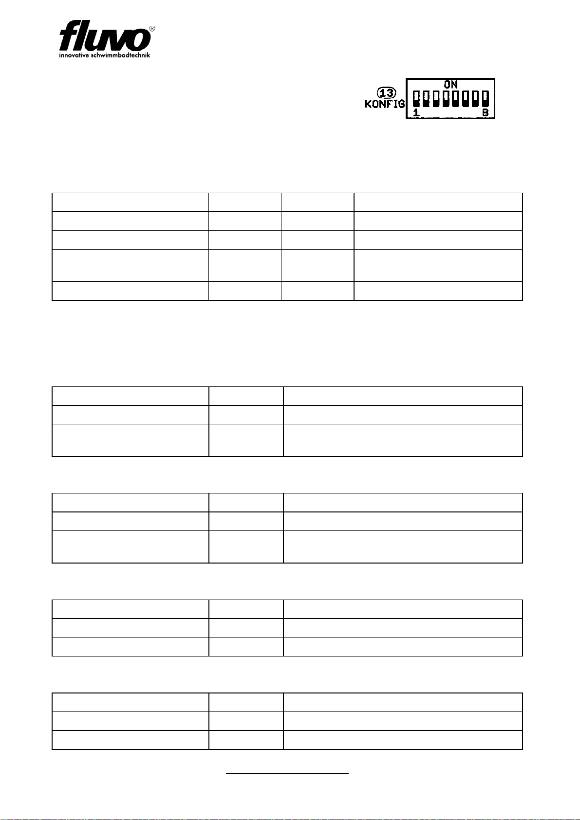
3.5 Configuration via DIP switch.......................................................................................8
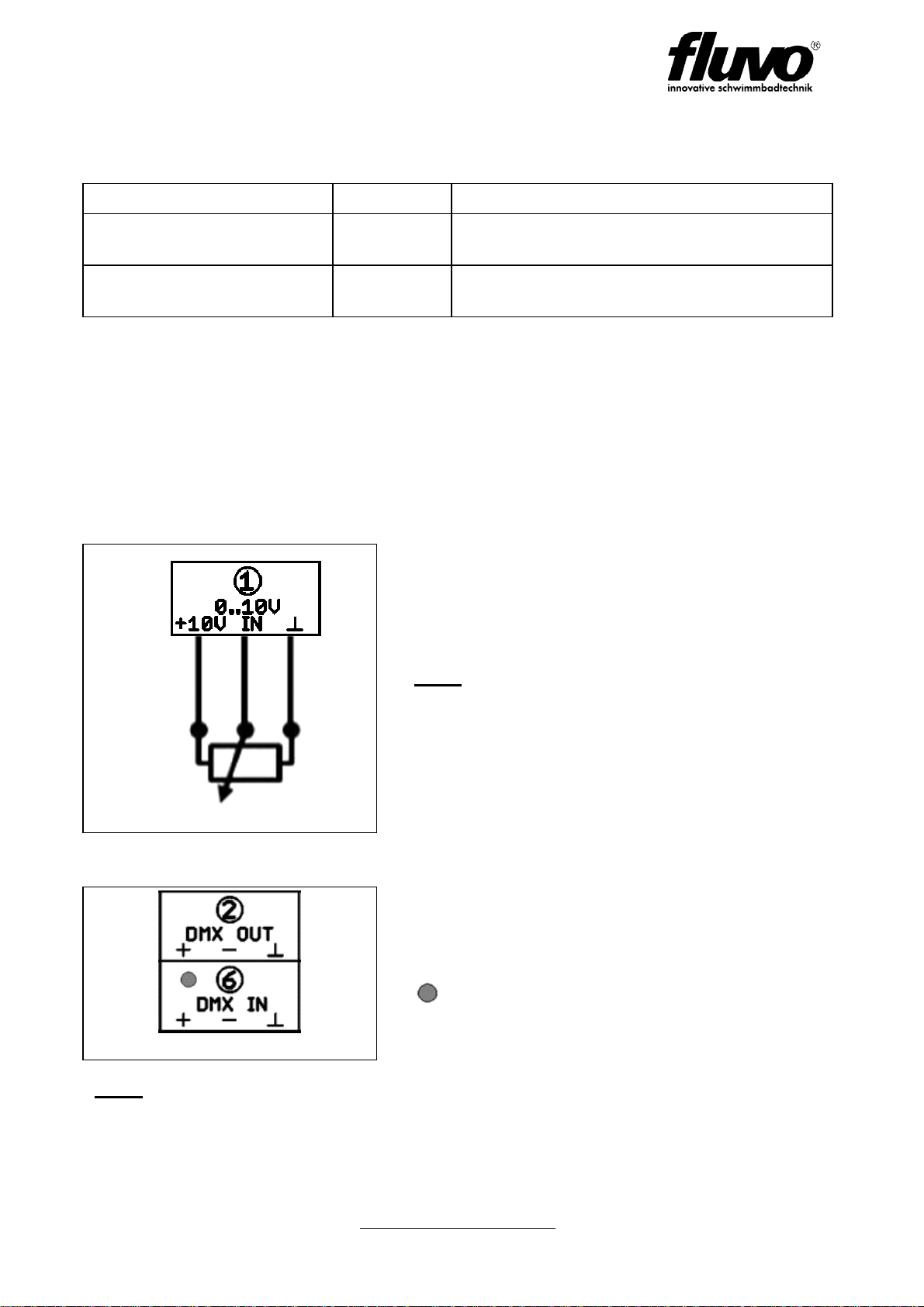
3.6 "Analog" control terminal.............................................................................................9
3.7 "DMX" control terminal................................................................................................9
3.8 "BUS" control terminal...............................................................................................10
3.9 DIAG system diagnosis button..................................................................................11
3.10 Sensor button connection diagram ...........................................................................12
4Functional Description.................................................................................13
4.1 Operating mode ........................................................................................................13
4.2 LED display...............................................................................................................14
4.3 Synchronisation of several LED control units............................................................14
4.4 Individual control of the RGB spotlights....................................................................15
4.5 Colour light control with customer-specific DMX control unit....................................15
4.6 External sensor button via converter box 3.0............................................................16
5Luchs-NT RGB and LED-white spotlights...................................................18
5.1 Standard....................................................................................................................18
6Installation of LuchsNT lighting unit...........................................................19
6.1 Installation instructions..............................................................................................19
6.2 Spotlights – LED control unit connecting cable.........................................................19
7Technical data...............................................................................................20
7.1 Technical specification..............................................................................................20
7.2 Dimensions ...............................................................................................................21
7.3 Device installation.....................................................................................................22
7.4 Type plate .................................................................................................................23
7.5 Guarantee seal..........................................................................................................23