Airsafe EOL-TE-LED User manual

Advanced Airport Lighting System
LED Elevated Omni-directional Lighting Fixtures
LED Elevated Taxiway Edge Light and LED Low Intensity Obstruction
EOL-TE-LED and EOL-OB-LED
Operation Manual
Please read this manual carefully before construction, installation and operation of the product.
Please keep this manual properly for further reference.
This manual is subject to change without prior notice.
Airsafe Airport Equipment Co., Ltd.

Advanced Airport Lighting System
I
Revision Description
No.
Description
Version
No.
Revised
by
Approved
by
Date
1
First release
V1.0
C.SY
W.GL
Aug. 2, 2008
2
Contents of LED obstruction light
added
V1.1
Z.H
C.SY
Oct. 10, 2016
3
Type and composing adjustment
added
V1.2
Z.H
C.SY
Nov. 29, 2016

Advanced Airport Lighting System
Table of Content
1.0 Foreword...............................................................................................................................- 1 -
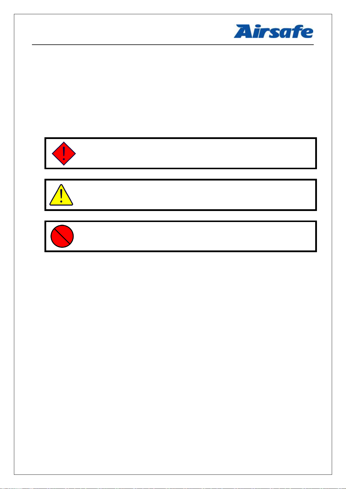
1.1 Illustrations and Meanings.............................................................................................- 2 -
1.2 Safety Rules and Notices ...............................................................................................- 3 -
1.3 Quality Assurance and Responsibility............................................................................- 4 -
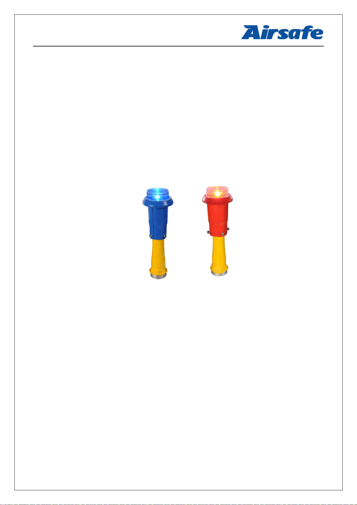
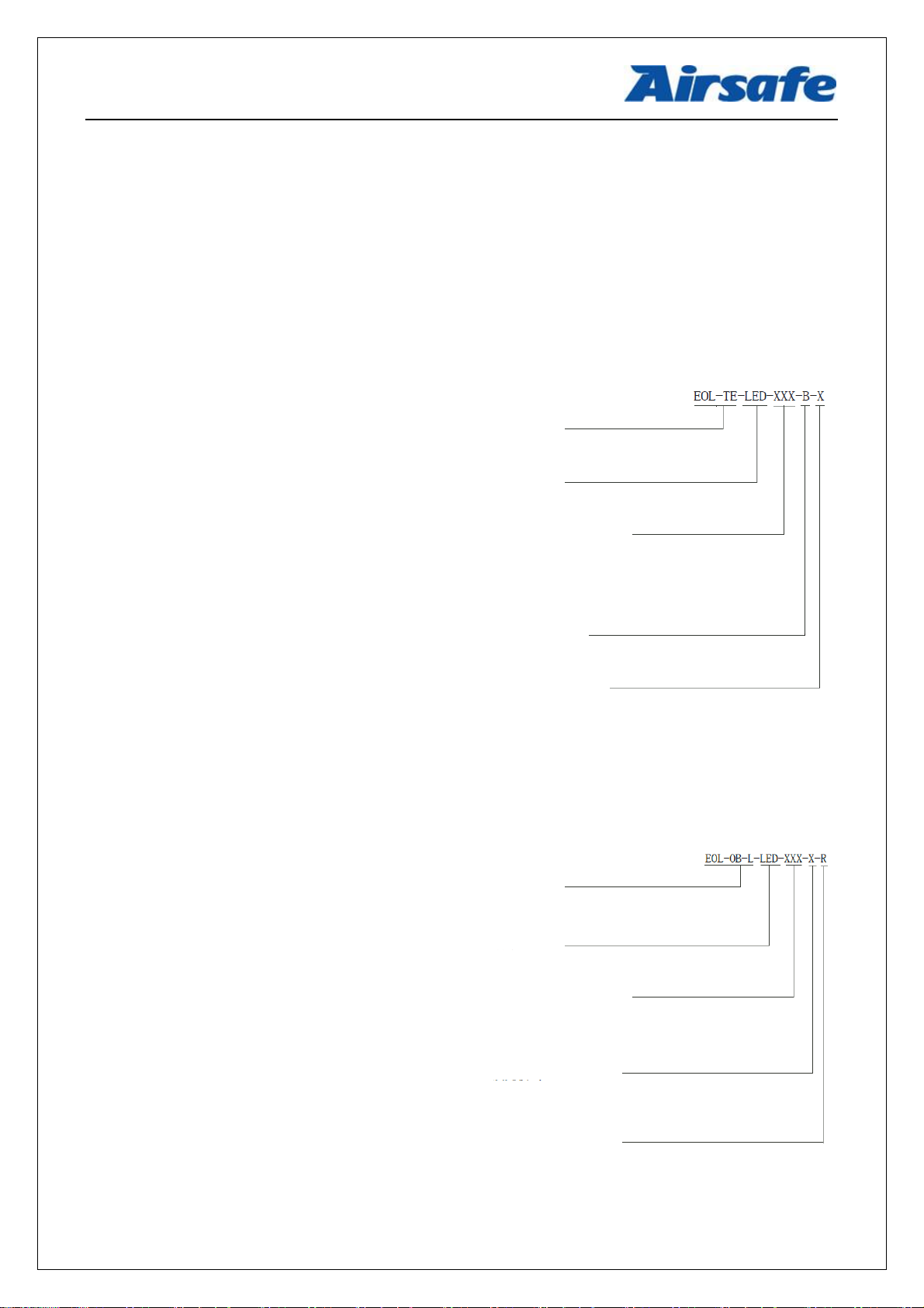
2.0 Introduction to Lighting fixtures............................................................................................- 5 -
2.1 Technical Specifications ................................................................................................- 6 -
2.2 Application Environment...............................................................................................- 7 -
2.3 Application Scope..........................................................................................................- 7 -
2.4 Technical Parameters.....................................................................................................- 7 -
2.5 Technical Features.........................................................................................................- 8 -
2.6 Structure........................................................................................................................- 9 -
2.7 Fault Detection or Lamp Bypass Functions..................................................................- 10 -
3.0 Installation ..........................................................................................................................- 11 -
3.1 Installation Tools .........................................................................................................- 12 -
3.2 Screw and Torsion .......................................................................................................- 12 -
3.3 Installation Method I: Installation of Flange Supporting Pavement ..............................- 13 -
3.6 Level Adjustment of Lighting Fixtures.........................................................................- 16 -
4.0 Operation and Control.........................................................................................................- 17 -
4.1 6.6ALighting Fixture Wiring Diagram ........................................................................- 17 -
4.2 Light Intensity Control of 6.6A Lighting Fixtures ........................................................- 18 -
4.3 Work of Lighting Fixtures with Constant Power Supply...............................................- 18 -
5.0 Replacement of Components of Lighting Fixtures...............................................................- 19 -
5.1 How to Replace Inverse Taper Prism ...........................................................................- 20 -
5.2 How to Replace Lamp and Drive.................................................................................- 21 -
5.3 How to Replace Frangible Pole....................................................................................- 23 -
6.0 Maintenance of Lighting Fixtures........................................................................................- 24 -
6.1 Daily Maintenance.......................................................................................................- 24 -
6.2 Regular Spot Check and Troubleshooting ....................................................................- 25 -
7.0 List of Components and Ordering of Spare Articles and Accessories............................- 26 -
8.0 Packaging, Transportation and Storage................................................................................- 28 -
8.1 Packaging and Weight .................................................................................................- 28 -
8.2 Transportation Mode....................................................................................................- 28 -
8.3 Storage ........................................................................................................................- 28 -

Advanced Airport Lighting System
- 1 -
1.0 Foreword
ICAO Airport Service Manual Part 9 “Airport Maintenance Practices” and FAA
AC150/5345-26 Maintenance of Airport Visual Aid Facilities are the highest criterions for site
installation and maintenance of such lighting fixtures. This manual was compiled with considerable
reference to these two criterions.
The content stated in this manual is absolutely important, so construction personnel must read
it carefully before construction. After properly understanding the entire content of this manual,
construction personnel should carry out the construction in strict accordance with the methods
specified herein, to ensure that the product is safely and properly installed in place.
Routine airport maintenance personnel should carry out the routine maintenance in strict
accordance with the methods specified by relevant provisions, to ensure that the lighting fixtures
are in the best operation condition.
Related personnel must strictly follow safety criterion. Any personnel without specialized
training is strictly forbidden to touch the lighting fixtures and devices. Live line work should be
avoided under any circumstances. Construction or maintenance personnel should get acquainted
with first-aid knowledge, in case of any unexpected events.

Advanced Airport Lighting System
1.1 Illustrations and Meanings
○Following illustrations will appear in this manual where necessary to remind or warn
construction or maintenance personnel.
○Please continue reading the subsequent content of this manual after properly understanding
the meanings of these illustrations.
To remind that the behavior may cause serious injury or death.
※Detailed description will be given in the box.
To remind that the behavior may cause injury to people or damage to
product.
※Detailed description will be given in the box.
To notify that the behavior is prohibited.
※Detailed description will be given in the box.

Advanced Airport Lighting System
1.2 Safety Rules and Notices
Using the light fixtures outside of airport is strictly prohibited.
※Inadequate maintenance or casual touch will cause light faults.
Using power supply other than CCR is strictly prohibited.
※Other power supply may cause damage to light source or other component of the
lighting fixtures, or even malfunctions of power supply.
Making sure that CCR is on power-off state before the installation or maintenance of the
lighting fixtures.
※Current surge produced during the installation of the lighting fixtures may cause damage
to light source.
Non-professional electricians are strictly forbidden to maintain any electrical fault of
the lighting fixtures.
※It may damage any electrical component of the lighting fixtures or cause bigger fault.
Live line maintenance of the lighting fixtures is strictly prohibited; in case of lightning
and/or thunderstorm, maintenance of the lighting fixtures is prohibited.
※It may cause electric shock accident.
Be careful when handling the lighting fixtures.
※Falling to the ground may cause damage of the optical cover or other internal
components of the lighting fixtures and injury of personnel.
Replace the lead immediately in case the jacket of second cable is damaged.
※It may cause short circuit, electric shock or other failure.
Don’t touch the damaged optical cover or other glass directly with hands.
※Glass fragments may scratch hands.
Touching the lighting fixtures with wet hand is strictly prohibited.
※It may cause electric shock or other accident.

Advanced Airport Lighting System
1.3 Quality Assurance and Responsibility
Any defect in design, material or workmanship, which may occur during proper and normal
use over a period of one year from date of installation but less than 15 months from date of
shipment, or within the warranty period of the tender, will be repaired or preplaced by
manufacturer free of charge. The warranty doesn’t cover the failures resulting from lamp burnt out,
improper maintenance, installation or operation, or damages due to snow ploughs. Manufacturer
shall not be liable to any further claims or particularly claims for damages not affecting the goods
themselves.

Advanced Airport Lighting System
2.0 Introduction to Lighting fixtures
This manual involves the following series lighting fixtures:
EOL-TE-LED-------------------------------LED Elevated Taxiway Edge Light
EOL-OB-LED-------------------------------LED Low Intensity Obstruction Light
Type of LED Elevated Taxiway Edge Light (EOL-TE-LED):
Type of LED low intensity obstruction light (EOL-OB-LED):
Type
EOL-TE= Elevated taxiway
edge light
Lamp
LED= LED lamp
Power supply mode
012=12V
024=24V
220=220V
066=6.6A
Beam color
B=Blue
Optional function
M= single lamp fault detection function
Type
Lamp
Low intensity obstruction
light
LED= LED lamp
Luminous mode
A: Excluding light control. Continuous lighting mode
B: Including light control. Continuous lighting mode
C: Including light control. Flash mode
Beam color
R= Red
Power supply mode
012=12V
024=24V
220=220V
066=6.6A

Advanced Airport Lighting System
2.1 Technical Specifications
This product conforms to the provisions of the following standards or technical specifications.
For dated standards or technical specifications, only the edition cited applies. For undated
references, the latest edition of the referenced document (including any amendments) applies.
International Electrotechnical Commission (IEC) TS 61827;
Convention on International Civil Aviation Annex 14- Aerodromes Volume 1;
International Civil Aviation Organization (ICAO)- Aerodrome Design Manual- Part 4: Visual
Aids;
Federal Aviation Administration (FAA) AC150/5345-46;
Federal Aviation Administration (FAA) EB 67;
GB/T 7256 General Requirements of Lighting Fixtures for Civil Airport;
Department of Airport of Civil Aviation Administration of China: Advisory Circular, Technical
Requirements for Runway and Taxiway Aid Lighting Fixtures (AC-137-CA-2015-03) ;
Department of Airport of Civil Aviation Administration of China, Advisory Circular, General
Technical Requirements for Civil Airport LED Aid Lighting Fixtures (AC-137-CA-2015-01) ;

Advanced Airport Lighting System
2.2 Application Environment
○Altitude: below 4,000m;
○Outdoor: -55°C ~ +55°C;
○Relative air humidity: not more than 95%;
○In rain, snow, ice and water;
○Expose to corrosive salt atmosphere.
○Basic earthquake intensity VII.
2.3 Application Scope
Elevated taxiway edge light and low intensity obstruction light for Category I, II and III
airports.
Using the lighting fixtures beyond the specified scope is strictly prohibited.
※Application beyond the specified scope will cause damage or risk to any
component.
2.4 Technical Parameters
Description
Type
Rated Power
Life of Light Source
Taxiway edge light
EOL-TE-LED-XXX-B-X
4VA
≥50,000h
Low intensity
obstruction light
EOL-OB-L-LED-XXX-X-R
4VA
≥50,000h

Advanced Airport Lighting System
2.5 Technical Features
○Long life, energy saving, maintenance free and other characteristics of LED will bring huge
economic benefits to customers;
○Prism with proprietary inverse taper structure is used, with high light utilization rate;
○Strict luminous angle of 0-6° ensures that the short-distance lighting fixtures do not make the
pilot dizzy;
○Dimming curve of the lighting fixtures is consistent with the change of halogen lamp, and
meets the requirements of FAA;
○Strict LED color management ensures the consistency of light color;
○The prism is made of the glass, whose surface resists the erosion of wind and sand;
○Unique taper design of the prism edge effectively prevents accumulation of rain, snow, wind
and sand;
○Proprietary drive circuit and thermal management solution greatly improve the reliability and
service life of the lighting fixtures;
○Power factor is greater than 0.9, which minimizes the grid interference;
○Optional single lamp fault detection function enables the light to be open as halogen lamp once
LED fails;
○Compact structure, attractive appearance, small windward area and strong wind resistance
capability;
○Main body of the lighting fixtures is made of aluminum alloy material with special anodizing
surface treatment, and all fasteners are made of stainless steel, thus being applicable to all kinds
of harsh environment;
○High precision components machining ensures dimensional quality and precision of the
lighting fixtures;
○Forged frangible device with precise machining, complying with FAAstandards and ensuring
stable and reliable performance;

Advanced Airport Lighting System
○The overall IP rating of the lighting fixtures reaches IP65, and it is difficult for the dust to be
deposited in them;
○A level tester may be directly placed on top of the lighting fixture prism for adjusting the level
angle of the lighting fixture;
2.6 Structure
1. Cover bracket
2. Prism
3. Body gasket
4. Lamp assy
5. Waterproof gland
6. Light body
7. Frangible pole
8. Plug

Advanced Airport Lighting System
2.7 Fault Detection or Lamp Bypass Functions
This product complies with the requirements of FAA EB67 and GB/T 7256, and integrates
single lamp fault detection function; or, it can provide the option of lamp bypass function in
accordance with the requirements of FAAAC150-5345/46.
Single lamp fault detection function: The light will take automatic action to cut off the input
when any malfunction occurs on the lamp and achieve an effect similar as the open circuit of
ordinary halogen light once it is burnt. This function is generally used in conjunction with single
lamp controller, to help single lamp control and monitoring system to identify any failed light. And
it is integrated into the interior of the lighting fixtures, without need of any external device. Please
specify this function during the ordering if needed.
Isolation
transformer
Light
apparatus
Isolation
transformer
Light
apparatus
Normal
shining
Light source
failure
Automatic
open circuit
Lamp bypass function: After any failure occurs to the lamp, relatively, the input terminal of
light will be short to the isolation transformer. This function is generally applicable to occasions
that one isolation transformer carries multiple lighting fixtures. If one or more of these lighting
fixtures is or are damaged, the remaining lighting fixtures will not go out thereby. This function is
integrated into the interior of the lighting fixtures, without need of any external device. Please
specify this function during the ordering if needed.
Isolation transformer
Light
Fixture 1
Normal
shining
Light
Fixture 2
Normal
shining
Light
Fixture n
Normal
shining
Isolation transformer
Light
Fixture 1
Normal
shining
Light
Fixture 2
Light source damage
Internal bypass
Light
Fixture n
Normal
shining

Advanced Airport Lighting System
3.0 Installation
Requirements for installation should be learned thoroughly before installation including
installation tools and site requirement, etc., to avoid malfunction of the light due to incorrect
installation.
It is very important to correctly install the lighting fixtures according to the design and site
situation. The site cleaning, connection of the lighting fixture connector and level calibration of the
lighting fixture will directly impact the normal function of the lighting fixtures.
The manufacturer requires the professional to install the lighting fixtures.
※The professional may ensure the normal operation of the lighting fixtures.
Prior to installation of the lighting fixtures, first check whether their parts, especially the glass
parts are intact. Their standard packaging is two lighting fixtures per box and the flange is their
accessory, which is separately packed. Carefully take out the lighting fixtures to avoid damaging
their assy;
When unpacking the lighting fixtures, please note whether the carton is intact.
※Damage to the carton may damage to the lighting fixture components.
There are three installation methods on the lighting fixture site, including flange floor
installation, embedded pipe installation and deep bucket installation. The installation methods of
the lighting fixtures corresponding to three different installation requirements are different a little.
The installation description of the lighting fixtures below is very important, please
carefully read it.
※Improper installation method is a main cause of failure of lighting fixtures.

Advanced Airport Lighting System
3.1 Installation Tools
Choosing right tools not only can ensure the correct and reliable installation of the lighting
fixtures, but also can reduce unnecessary safety accidents. Special Tools listed in the table may be
purchased from the manufacturer or any distributor. Universal tools are available on local hardware
market. Please pay attention to measurement range during procurement.
○Special tool- Elevated light nut wrench: be used to dismount
the lighting fixtures, and available directly from the
manufacturer or any distributor.
○Universal tool- Torque screwdriver: be used to dismount
screw, equipped with PH2 cross screwdriver, and sellable in
various hardware stores.
Recommended range is 1-6N.m.
3.2 Screw and Torsion
The torque listed in this section is only for reference by maintenance personnel. Correct
fastening force of screw can ensure normal operation of the lighting fixtures. If screw is too tight, it
will easily damage the lighting fixtures; on the contrary, if screw is easy to fly out, it may cause an
accident.
Serial No.
Screw Type
Tool
Torque
1
M6 screw
Internal hexagonal wrench
5 N·m
2
M4 screw
Force measuring screwdriver with cross screwdriver (PH2)
1.5 N·m
Please use torque wench or other special tool for installation.
※Informal tools may cause damage to fasteners or personal injury.

Advanced Airport Lighting System
3.3 Installation Method I: Installation of Flange Supporting Pavement
1. After taking out the lighting fixture, gently screw the flange onto the frangible pole at its
lower part.
2. Connect A6 plug of the lighting fixture with the secondary connector of the isolation
transformer or A7 receptacle, which must be reliable and ensure that there are no impurities
between the plug and receptacle.
3. Fix the flange with M10x50 expansion screws at the correct position.
Pressing the lead is prohibited during installation.
※Otherwise it may cause water to enter the lighting fixture or other failure
of the lighting fixture.
4. Apply force to screw the lighting fixture with a special wrench provided by the factory,
with its opening placed on the hexagonal plane under the V-shaped frangible groove on the
frangible pole.
“Elevated light nut wrench” is a special tool, please order it from the manufacturer.
The wrench must be placed in the hexagonal plane under V-shaped tank of
the frangible point for applying force.
※The frangible pole may be damaged or broken.
Light body
Frangible pole
Flange
Expansion screw
Frangible pole
V-shaped frangible groove
Wrench

Advanced Airport Lighting System
3.4 Installation Method II: Installation of Embedded Pipe without Flange
There shall be G2 thread on the embedded pipe.
1. When the A6 plug of the lighting fixture is connected with the secondary connector of the
isolation transformer or A7 receptacle, it must be reliable and ensure that there are no impurities
between the plug and receptacle.
2. Before the light body is screwed into G2 embedded pipe, in order to avoid the final broken
cable resulting from the cable strand in the lighting fixture, the set screw connecting the light body
and frangible pole must be first unscrewed and ensure that the light body on the lighting fixture is
not loosened when the lighting fixture is screwed in. The position of the set screw is shown in
Figure below:
3. After unscrewing the set screw, stably hold the light body with left hand, rotate the frangible
pole with right hand clockwise, gently screw the frangible pole into the G2 thread opening of the
upper opening of the embedded pipe when the light body is stable, until it is completely screwed in.
If the watertightness is required, the raw material belt shall be wound outside the G2 thread of the
frangible pole.
The upper light body must be kept stable when the frangible pole is rotated.
※It may cause water entry into the lighting fixtures or other faults of the
lighting fixtures.
4. Apply force to screw the frangible pole with a special wrench provided by the factory, with its
opening placed on the hexagonal plane under the V-shaped frangible groove on the frangible pole
(the same with the installation of the flange supporting pavement).
The wrench must be placed in the hexagonal plane under V-shaped tank of
the frangible point for applying force.
※The frangible pole may be damaged or broken.
5. Make the light body vertical and screw the set screw connecting it with the frangible pole.
Light body
Set screw
Frangible pole
Embedded pipe

Advanced Airport Lighting System
3.5 Installation Method 3: Deep Bucket Installation
In order to prevent the isolation transformer from being soaked in water due to accidental
inflow of the deep bucket, it is suggested to cushion the isolation transformer or other circuit
control boxes with brick or other objects.
When the flange on the deep base is not installed, install the lighting fixture by referring to the
“Installation Method I”. Please note that wind the raw material belt outside the G2 thread of the
frangible pole of the lighting fixture before screwing it into the flange.
When the flange on the deep base has been installed, install the lighting fixture by referring to
the “Installation Method II”. Please note that wind the raw material belt outside the G2 thread of
the frangible pole of the lighting fixture before screwing it into the flange.
The non-standard tools shall not be used for assembling and dismounting the
lighting fixtures.
※It may cause personal injury or damage to the lighting fixtures.

Advanced Airport Lighting System
3.6 Level Adjustment of Lighting Fixtures
After the lighting fixtures are installed, their level adjustment must be made to ensure that their
luminous angle is correct and reliable.
The level adjustment of the lighting fixtures is an important part which shall
not be omitted for their installation.
※No level adjustment may impact the overall light distribution effects of the
taxiway.
As shown in Figure above, place the level indicator on the upper prism surface of the lighting
fixture, with it aligned with any two opposite set screws, finely adjust these two set screws to make
the bubble of the level indicator in this director in the middle. Rotate the level indicator for 90º in
any direction, finely adjust the other two set screws in the front and rear direction to make the
bubble of the level indicator in this director in the middle. Randomly rotate the level indicator and
check the lighting fixture level at different angles. The whole fine adjustment process may be
repeated until the lighting fixture complies with the level requirements.
Finally, reconfirm that the set screw has been tightened.
Making sure that the set screw is tightened.
※Its looseness or drop onto the runway may cause accident.
Please use the horizontal corrector designated by the manufacturer.
※It may impact the horizontal adjustment effects of the lighting fixtures.
Level indicator
Set screw

Advanced Airport Lighting System
4.0 Operation and Control
This series lighting fixtures have several power supply modes for choice.
The lighting fixtures are applicable to CCR power supply 6.6A circuit special for airports,
which forms a secondary circuit with the lighting fixtures through secondary outgoing line of
isolation transformer connected on primary circuit. Due to the use of isolation transformer, the
damage of lamp of single lighting fixture will not affect whole series circuit.
4.1 6.6ALighting Fixture Wiring Diagram
LED lamp
Secondary connector
Isolation transformer
Primary connector
Open circuit
monitoring
This manual suits for next models
1
Table of contents
Other Airsafe Lighting Equipment manuals
Popular Lighting Equipment manuals by other brands

Stairville
Stairville Outdoor Stage PAR Hex TR1 user manual

iGuzzini
iGuzzini B213 installation instructions

Hamron
Hamron 008869 operating instructions

Soltech
Soltech SATELIS installation manual

Soundoff Signal
Soundoff Signal P Series instruction manual

Clevertronics
Clevertronics LP CBS2LEDS-DIF Series Installation and maintenance instruction