Schmalz SMPi 20 User manual

SCHMALZ SCPI /SMPI
Innovative Vacuum for Automation
EN
Operating Instruction
Compact ejector SMPi 20 and 25
30.30.01.00491/03 | 05.2017

SCHMALZ SCPI /SMPI
1-2
CONTENTS
1Safety instructions............................................................................................. 1-4
Important symbols....................................................................................................................... 1-4
General safety information.......................................................................................................... 1-4
Intended use................................................................................................................................ 1-5
2Start-up................................................................................................................ 2-6
Installation and operation............................................................................................................ 2-6
Electrical connection ................................................................................................................... 2-7
Pneumatic connection................................................................................................................. 2-7
Setting the blow-off volume flow ................................................................................................. 2-8
3Description.......................................................................................................... 3-8
Version overview......................................................................................................................... 3-8
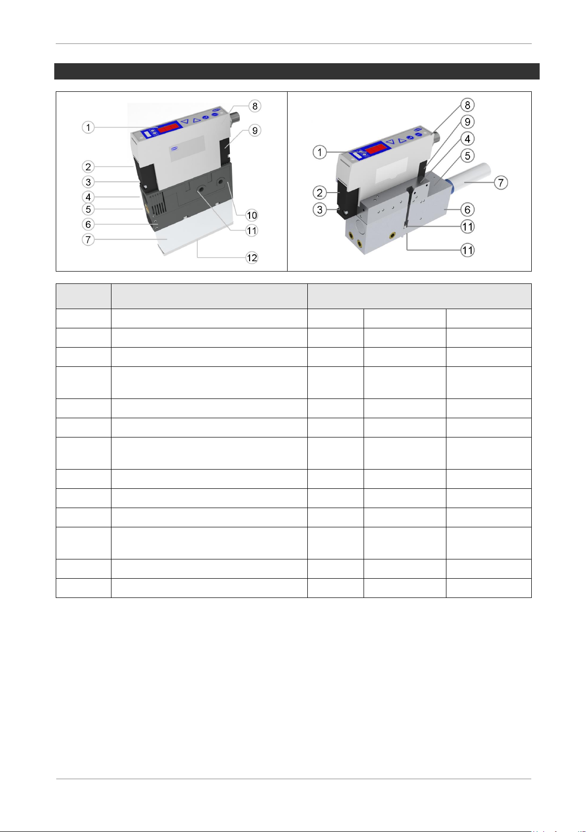
Ejector design.............................................................................................................................. 3-9
Operating and display elements.................................................................................................. 3-10
General function description........................................................................................................ 3-11
Operating modes......................................................................................................................... 3-13
Control concept for IMP ejectors................................................................................................. 3-14
Status display for system vacuum............................................................................................... 3-15
Valve LEDs.................................................................................................................................. 3-17
Monitoring of the valve switching frequency (valve protection function)..................................... 3-17
“Diagnostics” signal output (OUT 1) ............................................................................................ 3-17
4Operating and menu concepts.......................................................................... 4-18
Menu authorisation...................................................................................................................... 4-18
Manual mode............................................................................................................................... 4-19
Basic menu .................................................................................................................................... 4-20
Setting of switching points for the air-saving function with [H-1] and [h-1] ................................ 4-22
Setting of switching points for the signal output with [H-2] and [h-2].......................................... 4-23
Zero-point adjustment (calibration) [CAL] ................................................................................... 4-24
Counters, software versions and serial numbers...................................................................... 4-25
Cycle counters [ct1] and [ct2]...................................................................................................... 4-26
Displaying the cycle counters...................................................................................................... 4-26
Software version [SoC]................................................................................................................ 4-27
Serial number [Snr] ..................................................................................................................... 4-27
Configuration menu ...................................................................................................................... 4-28
Configuration of the vacuum unit [uni]......................................................................................... 4-30
Configuration of the signal output [out] ....................................................................................... 4-30
Configuration of the air-saving function [ctr]................................................................................ 4-31
Configuration of the blow-off function [bLo]................................................................................. 4-31
Rotating the display screen [dPy]................................................................................................ 4-32
Locking the menus using a PIN code [Pin] ................................................................................. 4-33
Resetting to the factory settings (Clear All) [rES]........................................................................ 4-34
5Maintenance........................................................................................................ 5-35
Spare and wearing parts ............................................................................................................. 5-36

SCHMALZ SCPI /SMPI
1-3
6Errors................................................................................................................... 6-37
Troubleshooting........................................................................................................................... 6-37
Error codes.................................................................................................................................. 6-37
7Technical data .................................................................................................... 7-38
Electrical data ................................................................................................................................ 7-38
Electrical connection ................................................................................................................... 7-40
Electric Connection ..................................................................................................................... 7-41
Internal wiring of electrical isolation ............................................................................................ 7-41
Mechanical data............................................................................................................................. 7-42
Dimensions.................................................................................................................................. 7-43
Pneumatic circuit plans ............................................................................................................... 7-45
Overview of display symbols....................................................................................................... 7-46
Factory settings............................................................................................................................. 7-47
8Declaration of conformity.................................................................................. 8-48

SCHMALZ SCPI /SMPI
1-4
1 SAFETY INSTRUCTIONS
Important symbols
This symbol identifies important information and instructions.
Caution!
This symbol identifies a potentially dangerous situation.
If it is not avoided, slight or minor injuries may result.
Danger!
This symbol identifies an immediate hazard.
If it is not avoided, death or serious injuries may result.
General safety information
These operating instructions contain important information on using the ejector. Please
read the operating instructions thoroughly and keep them for later reference.
Never look into any open or closed vacuum vents (e.g. vacuum connec-
tions or suction pads).
Serious injuries could occur as a result. Eyes can be sucked in.
Compressed air can cause closed containers to explode. A vacuum can cause closed
containers to implode.
The ejector may only be operated with a silencer. Never look into the exhaust air jet of
the silencer.
The ejector emits noise. We recommend wearing ear protection.
This device is not intended for use with hazardous dust, oil mist, vapours or aerosols,
etc. If drawn in, these materials will enter the exhaust air and may result in poisoning.

SCHMALZ SCPI /SMPI
1-5
Use only the connections, attachment holes and attachment materials that have been
provided.
Carry out mounting and removal only when the device is in a disconnected, depressur-
ised state.
Do not sit or stand in the area in which the picked-up payload is transported.
Do not sit or stand in the danger area while the machine or system is in automatic mode.
Components may be installed by trained specialist personnel only.
Specialist personnel must be familiar with the most current safety rules and require-
ments. These apply to the use of such components as solenoid valves and pressure
switches and to control units for devices, machines and systems, for example.
Specialist personnel must also be familiar with the system’s control concept. In particu-
lar, they must be familiar with the system’s redundant control components and feedback
signals.
Intended use
The ejector is designed for generating a vacuum for gripping and transporting objects when
used with suction pads. Neutral gases in accordance with EN 983 are approved as media to
be evacuated. Neutral gases include air, nitrogen, and inert gases (e.g. argon, helium and
neon). Aggressive gases or media such as acids, acid fumes, bases, biocides, disinfectants
or detergents are not permitted.
The ejector is not suitable to be used for the transportation or through-suction of
liquids or bulk materials such as granulates.
Personal injury or damage to the ejector may otherwise occur.
The ejector must not be used to fill pressurised containers or to drive cylinders,
valves or other pressure-operated function elements.
Personal injury or damage to the ejector may otherwise occur.

SCHMALZ SCPI /SMPI
2-6
2 START-UP
Installation and operation
For safe installation and smooth operation, please observe and maintain the following
points:
The ejector may only be operated via power supply units with protected
extra-low voltage (PELV). The system must incorporate safe electrical cut-
off of the power supply in compliance with EN60204.
The device may not be operated in environments where there is a risk of
explosion.
Risk of fire and explosion.
The device may not be operated outside its specified capacities.
Doing so may either cause the device to malfunctions or destroy the device.
During installation and maintenance, make sure that the ejector is disconnected
and depressurised and that it cannot be switched on again without authorisation.
Personal injury or damage to the ejector may otherwise occur.
Protect the ejector from being damaged at all times.
No modifications may be made to the ejector.
Exclusion of warranty if X-Pump has been opened by the customer.
Connection symbols and designations are located on the ejector.
These must be observed.
Only the intended connections may be used.
Pneumatic and electrical line connections must be securely connected and attached to
the ejector.
The ejector may be installed in any position.
If these notices are not observed, then malfunctions, material damage and serious injury
–including fatal injury –could occur as a result.
If the ejector is no longer operative, the components must be disposed of in an ecologi-
cally sound manner.

SCHMALZ SCPI /SMPI
2-7
Electrical connection
The electrical connection of the ejector is made using 8-pin M12 male connector. The pin
assignment is described in the “Technical data” chapter.
The plug connectors may not be connected or disconnected when the system is live.
The ejector may only be operated via power supply units with protected extra-low volt-
age (PELV). The system must incorporate safe electrical cut-off of the power supply in
compliance with EN60204.
The power supply, signal inputs and signal outputs have a maximum line length of 30
metres.
Pneumatic connection
Use only well maintained compressed air (air or neutral gas according to EN 983, filtered
40 µm, oiled or unoiled).
High quality compressed air is important for the prolonged service life of the ejector.
Dirt particles or foreign bodies in the ejector connections, hoses or pipelines can lead to
partial or complete ejector malfunction.
Hoses and pipelines should be laid as short as possible.
Insufficient compressed air is supplied if the internal diameter on the compressed air
side is too small. This prevents the ejector from performing as specified in its defined
performance data.
Excessive flow resistance occurs if the internal diameter on the vacuum side is too small.
This leads to both a reduction in suction power and increased suction times. Blow-off
times are also lengthened.
Hose lines must be laid without bends and crimps.
Only use the hose or pipe internal diameters recommended for the ejector. If this is not
possible, use the next largest internal diameter.
Line cross-section internal diameter1)
Compressed air side
Vacuum side
8 mm
9 mm
1) Based on a maximum hose length of 2 m

SCHMALZ SCPI /SMPI
3-8
Setting the blow-off volume flow
The valve screw for setting the blow-off volume flow is located underneath the vacuum con-
nection. The volume flow is reduced by turning the valve screw clockwise and increased by
turning it anti-clockwise. The valve screw is equipped with a stop on both sides.
Do not overwind the stop on the valve screw. A minimum volume flow of approx.
20% is always necessary for technical reasons.
The blow-off volume flow can be set between 20% and 100%.
3 DESCRIPTION
Version overview
Product name
Art.-Nr.
SMPi 20 IMP RD M12-8-PT SO (cpl. with connection distributor)
10.02.02.04441
SMPi 20 IMP RD M12-8-PT SO (without connection distributor)
10.02.02.04442
SMPi 25 IMP RD M12-8-PT SO (cpl. with connection distributor)
10.02.02.03480
SMPi 25 IMP RD M12-8-PT SO (without connection distributor)
10.02.02.03334
SMPi 25 IMP ISO_01 RD M12-8-PT SO(without connection distributor)
10.02.02.03649
SMPi 25 IMP ISO_01 RD M12-8-PT SO(cpl. with connection distributor)
10.02.02.03650
SMPi 25 IMP ISO_02 RD M12-8-PT SO(without connection distributor)
10.02.02.03646
SMPi 25 IMP ISO_02 RD M12-8-PT SO(cpl. with connection distributor)
10.02.02.03648
Connection distributor ASV SMPI/SCPI 2xM12-4
10.02.02.03335

SCHMALZ SCPI /SMPI
3-9
Ejector design
Item:
Description
Max. torque
SMPi
SMPi ISO-01
SMPi ISO-02
1
Operating and display elements
2
"Blow-off" valve (NC valve)
0,75 Nm
G3/8“ 0,75 Nm
G1/4“ 0,75 Nm
3
Button for operating the "blow-off"
valve manually
4
Vacuum connection with 3/8" thread
10 Nm
10 Nm
10 Nm
5
Valve screw for blow-off volume flow
6
Integrated power blow-off module
for maximum blow-off volume flow
7
Silencer
8
Electrical connection plug M12, 8-pin
hand-tight
hand-tight
hand-tight
9
"Suction" valve (pulse valve)
0,75 Nm
0,75 Nm
0,75 Nm
10
Compressed air connection with 1/4"
thread
10 Nm
ISO-01
ISO-02
11
Ejector mount
6 Nm
1 Nm
1 Nm
12
Securing screw for silencer
1 Nm
1 Nm
1 Nm

SCHMALZ SCPI /SMPI
3-10
Operating and display elements
The ejector can be set and operated easily using the membrane keypad. The current
vacuum and setting values are shown on the three-digit display.
Item
Description
1
LED for blow-off valve
2
Status display for system vacuum
3
H1 LED (air-saving function) and H2 LED (parts control signal output)
4
Display (3-digit/7-segment)
5
DOWN button
6
UP button
7
ENTER button
8
MENU button
9
LED for suction valve

SCHMALZ SCPI /SMPI
3-11
General function description
VACUUM GENERATION (WORKPIECE PICK-UP)
The ejector is designed for handling parts using a vacuum together with suction systems.
The Venturi nozzle is activated by the "suction" signal input. On IMP versions, the "suction"
signal input is evaluated for its pulse. This means that "suction" mode is activated on the
ejector when an pulse of at least 50 ms is present. A longer pulse does not affect functional-
ity.
An integrated sensor records the vacuum generated by the Venturi nozzle. This is evaluated
by an electronics system and forms the basis of the system status display.
The ejector is available with (RD ejectors) and without (VD ejectors) the air-saving function.
On versions with the air-saving function, the ejector automatically regulates the vacuum
when in suction mode. The electronics system switches the Venturi nozzle off when the H1
switching point set by the user is reached.
The set switching point H1 might be exceeded considerably before the vacuum
is switched off when small volumes are to be evacuated. This system behaviour
does not constitute an error.
When objects with solid surfaces are picked up, the integrated non-return valve prevents the
vacuum from dropping. If the system vacuum drops below the switching point [H1-h1] due to
leaks, the Venturi nozzle is switched back on.
When in automatic mode, the ejector maintains "suction" mode if the power supply fails.
This prevents objects that have been picked up from falling off the suction pad in the event
of a power supply failure. This also applies when the ejector was set to “Venturi nozzle inac-
tive” with air-saving mode activated. In this case, the ejector switches to “Venturi nozzle ac-
tive” (i.e. continuous suction). The energy required to actuate the suction valve (pulse valve)
is supplied in this case by integrated capacitors. When the power supply returns, the ejector
remains in automatic mode with activated air-saving function. If the ejector is in "blow-off"
mode when the power supply fails, the blow-off is stopped and the ejector is set to “Pneu-
matically OFF”. This prevents unnecessary consumption of compressed air, thus saving
energy and additional costs. When the power supply returns, the ejector remains in the
“Pneumatically OFF” state.
The power supply is monitored by the electronics system. If the power supply drops below
approximately 21 V, then the air-saving function is deactivated. The suction and blow-off
signal inputs are also no longer processed.

SCHMALZ SCPI /SMPI
3-12
BLOW-OFF (DEPOSITING THE WORKPIECE)
In "blow-off" mode, the vacuum circuit of the ejector is supplied with compressed air. This
ensures that the vacuum drops quickly, depositing the workpiece quickly as well. "Blow-off"
mode is activated by the "blow-off" signal input.
"Suction" mode is simultaneously switched off through the "blow-off" signal input.
On pulse-controlled ejectors, if the suction signal input is still present following the blow-off
status, it is not evaluated. The ejector does not switch to suction mode until after another
pulse.
The blow-off valve is also equipped with a button for manual operation. Using the button for
manual operation, the valve can be set to blow-off mode without a power supply.
The ejector must not be operated with a closed vacuum connection.
Personal injury or damage to the ejector may otherwise occur.
The ejector also has a manual mode. In this mode, the ejector can be controlled
using the buttons on the membrane keypad. See the “Manual mode” chapter for
more details.

SCHMALZ SCPI /SMPI
3-13
Operating modes

SCHMALZ SCPI /SMPI
3-14
Control concept for IMP ejectors
Suction
signal input
IN1
Blow-off
signal input
IN2
Suction
mode
Blow-off
mode
IMP ejectors are set to “Pneumatically OFF” on delivery. The ejector only starts
the suction procedure after a valid pulse is sent through the suction signal input.

SCHMALZ SCPI /SMPI
3-15
Status display for system vacuum
The ejector is equipped with a status display for the system vacuum and monitoring func-
tions. System states are indicated in RED or GREEN. The status display is updated after
every suction cycle that is activated over the suction signal input.
During conventional suction cycles, the status display is used to display the system vacuum
level based on the H1 switching point. The status display goes out after a conventional suc-
tion cycle ends.
VACUUM MONITORING
Status display
Vacuum monitoring
GREEN
Rising vacuum: Vacuum H1
Falling vacuum: Vacuum H1-h1
RED
Vacuum < H1
MONITORING FUNCTIONS
If the H1 switching point is never reached within a suction cycle, then the status display re-
mains RED, even after the cycle is finished and the diagnostic signal output is set..
The ejector has a valve protection function. With the air-saving function activated [ctr=on]
and high leakage rates in the gripper system, the ejector switches constantly between the
“Venturi nozzle active” and “Venturi nozzle inactive” states. The number of valve switching
procedures thus increases rapidly within a short time. In order to protect the ejector and in-
crease its service life, the ejector switches the air-saving function off automatically at a
switching frequency of > 6/3 seconds and activates continuous suction (i.e. the ejector then
remains in the “Venturi nozzle active” state). The status display remains RED until the next
suction cycle and the diagnostic signal output is set.
Status display
Monitoring function
Reaction of ejector
RED
H1 never exceeded in suc-
tion cycle
-
Suction valve switches
> 6/3 seconds
(RD ejectors)
Ejector is set to continuous suc-
tion (i.e. the ejector then remains
in the “Venturi nozzle active”
state - valve protection function)

SCHMALZ SCPI /SMPI
3-16
STATUS DISPLAY OVERVIEW
Suction cycle with H1
reached
VD ejectors
RD ejectors:
[ctr=on] and no leakage or
[ctr=oFF]
Suction cycle with vacuum-
regulation (air-saving
function)
RD ejectors: [ctr=on]
Suction cycle with vacuum-
regulation (air-saving func-
tion) where the valve protec-
tion function was activated
RD ejectors: [ctr=on]
Suction cycle where H1 is
never exceeded
VD ejectors
RD ejectors
Key:
S: Vacuum ON
B: Vacuum OFF, blow off ON
r: RED
g: GREEN

SCHMALZ SCPI /SMPI
3-17
Valve LEDs
The suction and blow-off valves are each assigned an LED.
LED
LED state
Ejector state
Suction valve
LED is continuously lit
NO: No suction on ejector
NC: Suction on ejector
IMP: Suction on ejector
Blow-off valve
LED is continuously lit
Ejector blows off
Monitoring of the valve switching frequency (valve protection function)
If the suction valve is triggered more than six times within three seconds by the air-saving
function, then the ejector is set to continuous suction (i.e. it remains in the “Venturi nozzle
active” state). The status display turns RED. This indicates the valve protection function.
This remains in place until the next suction cycle begins.
“DIAGNOSTICS” SIGNAL OUTPUT (OUT 1)
The following events activate the “Diagnostics” signal output (OUT 1):
H1 is never reached during the suction cycle
Suction valve activates > 6/3 s (valve protection function)
The “Diagnostics” signal output remains activated until the next suction cycle begins.

SCHMALZ SCPI /SMPI
4-18
4 OPERATING AND MENU CONCEPTS
The unit is operated via four buttons on the membrane keypad. Settings are made using
software menus. The operating structure is divided into settings in the basic menu and con-
figuration menu. Setting of the ejector in the basic menu is sufficient for standard applica-
tions. An extended configuration menu is available for applications with special require-
ments.
The ejector is set to display mode when outside the menus. The current vacuum is dis-
played.
The unit of the current vacuum can be displayed by pressing the button.
Menu authorisation
Menus can be protected against unauthorised access by defining a PIN code [Pin] in the
configuration menu. [Loc] flashes in the display when the lock is active, or the PIN code is
requested.
The menus are accessed as follows:
Press the button.
Enter the first digit of the PIN code using the or buttons.
Confirm by pressing the button.
Enter the remaining digits in the same way.
Press the button to activate the menus.
The lock is activated again automatically after the selected menu or function is exited. The
PIN code “000” must be set for permanent deactivation of the lock.
The PIN code is set to “000” on delivery, meaning the menus are not locked.
If an incorrect PIN code is entered, then [Loc] is displayed and the menus
remain locked.
If the correct PIN code has been lost, then the ejector must be sent back to the
manufacturer for authorisation.

SCHMALZ SCPI /SMPI
4-19
Manual mode
The output signals may change during set-up in manual mode.
Ensure that the machine or system does not start moving as a result.
Personal injury or damage to the ejector could occur as a result.
Manual mode is used for locating and eliminating leaks in the vacuum circuit. The ejector
can be controlled manually using the buttons on the membrane keypad. In this operating
mode, the H1 and H2 LEDs both flash.
ACTIVATING MANUAL MODE
Activate manual mode as follows:
Press and hold the and buttons down at the same time for more than 3 sec-
onds.
MANUAL SUCTION
Suction mode is activated in manual mode by pressing the button. Exit suction mode by
pressing the button again or by pressing the button.
This is also active in manual mode when the air-saving function is activated
[ctr=on].
The valve protection function is not active in manual mode.
With this type of ejector, blow-off mode cannot be activated when in manual
mode.
DEACTIVATING MANUAL MODE
Manual mode is exited from the “Pneumatically OFF” idle setting using the button.
Manual mode is also exited when the status of the external signal inputs is changed.
The automatic exiting of manual mode through changes to external signals can
cause a handled object to move (suction or blow-off).

SCHMALZ SCPI /SMPI
4-20
BASIC MENU
All settings for standard ejector applications can be made and observed using the basic
menu.
4-22
Setting of switching points for
the air-saving function
4-23
Setting of switching points for
the signal output
4-24
Setting the blow-off time
4-25
Zero-point adjustment
(calibration)
This manual suits for next models
1
Table of contents
Other Schmalz Accessories manuals
Popular Accessories manuals by other brands

PCB Piezotronics
PCB Piezotronics 208A23 Installation and operating manual

Omcan
Omcan 10996 instruction manual

Pepperl+Fuchs
Pepperl+Fuchs ML100-55-G/95/102 quick start guide

Siemens
Siemens SITRANS WW100 operating instructions

Silvercrest
Silvercrest SLS 2200 B1 User manual and service information

IB Connect
IB Connect Cubo user manual