schmersal bp408 User manual

Operating Instructions
The bp408 Safety Circuit
General instructions
EC Type Examination
Safety Circuit


Operating Instructions- The bp408 Safety Circuit - Contents 3
This document has been translated from the German source text. If there is any conflict
between this translation and the German version, only the German version shall be
legally considered as binding.
Manufacturer: Böhnke + Partner GmbH Steuerungssysteme
Heinz-Fröling-Straße 12
51429 Bergisch Gladbach
Deutschland
Tel.: +49 2204 9553-0
Fax: +49 2204 9553-555
www.boehnkepartner.de
Hotline: Tel.: +49 2204 9553-444
Mail: service@boehnkepartner.de
Release:March 2023
Copyright: © Böhnke + Partner GmbH Control systems, 2023
This manual in its entirety is protected by copyright.
All rights, especially the right of translation, presentation, reproduction, duplication by
photocopying or in some other ways, storage on electronic medium and modification as
a whole or in parts are reserved for the publisher.
This manual does not provide information on our overall delivery options.
In spite of the care taken in creating texts, illustrations and programs, we accept no legal
liability whatsoever for possible mistakes or their consequences.
The common names, trade names, product identifications etc. in this document may also
be registered brands even if they are not specifically identified and as such are subject
to statutory provisions.
Böhnke + Partner GmbH, BlueModus, WinMOS®300, CANwizard®, Lift2CLOUD®

4Operating Instructions- The bp408 Safety Circuit - Contents
Contents
Contents..................................................................................................................................4
1General Information....................................................................................................5
1.1 Thank you....................................................................................................................5
1.2 Intended Use ...............................................................................................................6
1.3 Documetation References .........................................................................................6
2Product Certificates....................................................................................................7
2.1 Declaration of Conformity..........................................................................................7
2.2 EU Type Examination .................................................................................................7
2.3 EU Type-Examination Certificate SPL-01 with SMZ ................................................8
3UCM requirements......................................................................................................9
3.1 Requirements regarding certified safety devices....................................................9
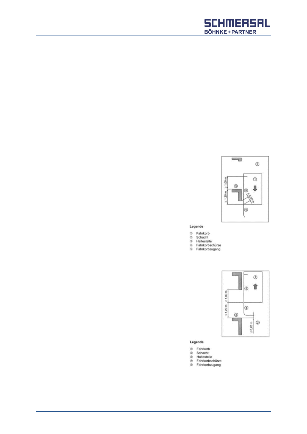
3.1.1 Fig. 1: Cabin moving downward.................................................................................. 9
3.1.2 Fig. 2: Cabin moving upward ...................................................................................... 9
3.1.3 Observation of the situation ...................................................................................... 10
3.2 General Information on UCM Function...................................................................11
3.2.1 Storage, Transport and Operating Conditions .......................................................... 11
3.2.2 Notes on Installation.................................................................................................. 12
3.2.3 Notes on function ...................................................................................................... 12
3.2.4 Notes on test ............................................................................................................. 13
3.3 Bp408 Testing Program ...........................................................................................14
3.3.1 General Testing Sequence ....................................................................................... 14
3.3.1.1 Step 1 ........................................................................................................................ 14
3.3.1.2 Step 2 ........................................................................................................................ 16
3.3.1.3 Step 3 ........................................................................................................................ 17
3.3.2 Extra requirements for UCM testing of traction elevators with gears........................ 18
3.3.3 Extra requirements for UCM testing of hydraulic elevators....................................... 19
3.3.4 Entries in stack memory............................................................................................ 19
4Circuit Board SPL-01................................................................................................20
4.1 Layout ........................................................................................................................20
4.2 Installation Requirements........................................................................................20
4.3 Query Circuit on SPL-01 .........................................................................................-20
4.3.1 Area of Application .................................................................................................... 20
4.3.2 Testing of wiring for query circuit .............................................................................. 21
4.4 Safety Circuit on SPL-01 ..........................................................................................22
4.4.1 Functional description of safety circuit ...................................................................... 22
4.4.2 Error analysis of safety circuit ................................................................................... 22
4.4.3 Testing....................................................................................................................... 23
4.5 Connection of SPL-01 ..............................................................................................24
4.6 Safety circuit status bar on display ........................................................................24
5Tecnical Data.............................................................................................................25

Operating Instructions- The bp408 Safety Circuit - General Information 5
1 General Information
1.1 Thank you.
Thank you for the trust that you have shown in Böhnke + Partner GmbH by
purchasing a "bp408" system.
Please take the time to read these descriptions carefully. Improper handling may
cause a high risk of injury.
Please observe all instructions and notes. This will save you a lot of time during
commissioning and will avoid the need for further inquiries
The term "manual" is used to refer to our entire set of documentation, which we
use to inform our customers of our company and its products. To improve clarity
and structuring, the manual was divided into multiple parts. The Operation
Instructions of the bp408 Safety Circuit" also considers the dangers and risks,
which may lead to severe health related as well as economic damage in case of
misuse. Additionally, you are also provided with the information required in order
for commission the safety circuit and to check its functions.
Should you still have any questions, you can reach us via:
Böhnke + Partner GmbH
Steuerungssysteme
Heinz-Fröling-Straße 12
51429 Bergisch Gladbach
Deutschland
Tel.: +49 2204 9553-0
Fax: +49 2204 9553-555
Hotline: +49 2204 9553-444
www.bp408.de
www.boehnkepartner.de

6Operating Instructions- The bp408 Safety Circuit - General Information
1.2 Intended Use
The safety circuit is an operating resource for use in industrial high-voltage systems
and is used exclusively for the processing of information as part of an elevator
control system.
1.3 Documentation References
This manual does not provide information on our overall delivery options. All
information only serves to describe the product and must not be regarded as
granted characteristics in the legal sense. Any claims for damages against us,
irrespective of the legal basis, are excluded unless we are guilty of deliberate intent
or gross negligence. We do not assume any guarantee that the specified circuits
or procedures are free of copyrights of third parties.
Reproduction, even in extracts, is permissible only with the consent of
Böhnke + Partner GmbH and with precise reference to the source.
Böhnke + Partner logo and company name are protected trademarks.
The information in this manual is regularly checked. The necessary corrections are
included in subsequent editions.
Hazard warnings and special information are given in this technical manual in the
following way and highlighted with a corresponding symbol.
CAUTION!
This symbol is used when inaccurate compliance with or failure to comply with
instructions or procedures can result in damages to the device, injuries, or fatal
accidents.
WARNING!
This symbol is used when inaccurate compliance with or failure to comply with
instructions or procedures can result in injuries or fatal accidents due to electric
current.
NOTE!
This symbol is used to bring attention to a specific characteristic.

Operating Instructions- The bp408 Safety Circuit - Product Certificates 7
2 Product Certificates
2.1 Declaration of Conformity
The declarations of conformity of the control components used can be found in the
latest versions in our online catalogue in the Lift Technology section at the
documents of the respective component:
https://products.schmersal.com/en_IO/bp408-806.html:
2.2 EU Type Examination
The system module bp408 contains an electronic monitoring unit for the safety
circuit and a precontrol for the contactors. Moreover, a safety circuit (SMZ) is
located on the circuit board. The safety circuit can be used in the following cases
of DIN EN 81-20/-50 and DIN EN 81-1/-2:
Preparatory measures with lift car and shaft door open
Levelling with lift car and shaft door open
Re-levelling with lift car and shaft door open
Detection of an unintended movement of the lift car with open doors (UCM).
Figure 1:
Document area in online
catalogue for the bp408

8Operating Instructions- The bp408 Safety Circuit - Product Certificates
2.3 EU Type-Examination Certificate SPL-01 with SMZ
Figure 1:
System module bp408
- Subarea of the printed circuit board SPL-01
Reg. no.
01/208/4A/6135.00/18 dated 2018-07-26.

Operating Instructions- The bp408 Safety Circuit - UCM requirements 9
3 UCM requirements
3.1 Requirements regarding certified safety devices
The safety precautions against unintended car movements have been developed
further and are required as UCM as part of EN 81-20/-50 and EN 81-1/-2.
This standard applies for all new installations and modernizations from end of 2014.
In accordance with the new requirements, all elevators must be fitted with a
certified safety device, which prevents uncontrolled movements of the car/cabin
with the door opened at a level, but which brings the car/cabin to a stop within a
designated area as shown in the figure in any case.
3.1.1 Fig. 1: Cabin moving downward.
The cabin floor must come to a stop max. 1.2 m
beneath the level position. There must be a
residual space of at least 1.0 m between the
upper edge of the cabin and the stepping edge
of the shaft.
3.1.2 Fig. 2: Cabin moving upward
The cabin floor must come to a stop max. 1.2 m
above the level position. There must be a
residual space of at least 1.0 m between the
cabin floor and the upper edge of the shaft
access. The apron fitted beneath the cabin may
only allow for a gap of max. 200 mm.
Fig. 1
Fig. 2

10 Operating Instructions- The bp408 Safety Circuit - UCM requirements
3.1.3 Observation of the situation
To satisfy this requirement in accordance with EN 81-20/50, a sensor module must
detect the unintended movement with the car/shaft doors open and trigger a
present and certified "braking and arresting device".
The possible danger area is the door area. This area is limited by the safety circuit
on "SPL-01". If the door area is left, the circuit detects this condition within a max.
of 10 ms, deactivates all driving signals and the "braking and arresting device"
immediately stops the car.
This faulty movement is detected by the control system and the installation is
blocked from further use. This block is also active after a power failure and
restoration of power and can only be reset from directly within the control system.
The error is also entered into a fault stack memory including its date and time.

Operating Instructions- The bp408 Safety Circuit - UCM requirements 11
3.2 General Information on UCM Function
3.2.1 Storage, Transport and Operating Conditions
CAUTION!
Improper storage, transport or operating conditions can result in destruction of the
system and danger to persons.
Storage and transport conditions
Ambient temperature: -20 °C to 70 °C,
relative humidity up to max. 90% (non-condensing)
Operating conditions
Ambient temperature: 0 °C to 60 °C,
relative humidity up to max. 90% (non-condensing),
Max. height
- Types 230 V AC and 110 V AC: 2000 m
- Type 48 V AC/DC: 4000 m
The ambient temperature of the control cabinet must not exceed +40 °C and
its average value over a period of 24 h must not exceed +35 °C. If the
operating temperature is below 5 °C, disturbance of visible characters on the
LCD is expected. At ambient temperatures >40 °C, the control cabinet must be
cooled with a cooling unit. Existing inlets and outlets for air conditioning must
be kept free.
Aggressive mediums, dust, fog, water, or humidity must not reach the
assemblies. The control cabinet should hence fulfil at least protection class
IP2xD.
Condensation must be avoided on all components!
Example: Water condensation in damp machine room after the control system
is switched off
In critical environments, please ensure there is sufficient sound insulation to the
building.
Out system controls are designed for primary voltage 230 V AC 50 Hz.
When using residual current protective circuits in control systems having
frequency converters, it must be ensured that these RCD circuit breakers must
be sensitive to universal current. Other RCD circuit breakers must not be used
in accordance with DIN VDE 0160, 5.5.3.4.2 because the DC residual current
generated through the input circuit of the frequency converter could increase
the minimum triggering level of RCD circuit breaker culminating in non-triggering.
The maximum permissible release current of these selective RCD circuit
breakers that are sensitive to universal current must not exceed value IΔN=0.3 A.

12 Operating Instructions- The bp408 Safety Circuit - UCM requirements
3.2.2 Notes on Installation
a) The UCM components must be used as intended and in accordance with
requirements. The operating instructions for the entire system (acquisition by
the elevator installing company) must be available.
b) The certificate containing the correct combination of the subsystems used with
the elevator system must be provided in order to satisfy UCM requirements.
c) The elevator installing company must present the documentation on the
installed UCM components.
d) The test instruction for the specialist must be provided with the elevator system.
3.2.3 Notes on function
a) Zone monitoring (max. +/- 350 mm = zone area for shaft and cabin door jointly
power operated, otherwise +/ 200 mm = zone area) controlled by a sensor,
which detects unintended movements of the cabin out of the door zone area
with the door opened.
b) If the speed in the zone area is exceeded by >0,3 m/s the safety circuit will
switch off.
c) The safety circuit detects this condition and switches off the drive unit safely.
The brake certified in accordance with UCM, the valve, the rope brake or a
suitable safety gear then arrest the cabin in a secure location.
d) The zone circuit (SMZ) on SPL-01 is used for UCM control. A magnetic switch
is sufficient for channel 1 and a position signal from the lift controller for
channel 2.
e) The reaction times of all components must be described.
f) The required UCM distances (Fig. 1+2) must be maintained as described in
standards EN 81-20 (5.6.7) in the event of an unintended movement with open
cabin/shaft door in the zone area.
g) If the braking system cannot bring the cabin to a stop within the required UCM
distances, then the door zone may be reduced in size. The maximum
acceleration for relevelling must be considered.
h) The lift controller monitors the level position of the cabin.

Operating Instructions- The bp408 Safety Circuit - UCM requirements 13
3.2.4 Notes on test
a) The specialist must check the installed safety components for their conformity
with UCM.
b) The "UCM" test instruction must be supplied with the elevator system (see
UCM testing program).
c) The specialist's test requirements for the SPL-01 safety circuit must be clearly
described and be comprehensible for new and recurring inspections and
acceptance testing of the system.
d) The specialist must follow the described instructions step by step.
e) A testing program is integrated with the bp408 system module for support
purposes.
f) The specialists check the provided acceptable limit values of EN 81-20/50
and/or EN 81-1/2+A3 (for example distances) on the elevator system by
measuring.
g) The specialist must confirm the measured values in his testing protocol.

14 Operating Instructions- The bp408 Safety Circuit - UCM requirements
3.3 Bp408 Testing Program
The tests for the following variants are described herein:
a) Gearless drive unit with UCM braking system on the traction sheave.
b) Drive unit with gear (without UCM braking system on the traction sheave) and
with UCM speed limiter and UCM safety gear.
c) Hydraulic elevator (UCM valve)
The testing sequence must be observed.
3.3.1 General Testing Sequence
During the test the overspeed monitoring of the lift controller is disabled.
3.3.1.1 Step 1
In order to check this function prior to commissioning, the bp408 system module
contains a test program The test program is activated by a password in the
maintenance menu.
The password can be assigned by the user in the setup menu and may amount to
a maximum of eight digits. The default code upon delivery is “8103”.
After entering of the test code, a warning note is provided on the display of the
control system.
The hazard warning "Caution! Refer to the testing
instructions!" appears in the display of the control
system after activating the testing mode.

Operating Instructions- The bp408 Safety Circuit - UCM requirements 15
In order to perform the UCM test (A3) with the door opened or closed, this can be
configured using the following parameter.
If the setting for open doors is selected, the following note appears:
After confirming with "OK", the user can then
navigate to the next point by pressing the
directional key in the downward direction. This is
described in the following chapter.
NOTE!
If a testing sequence with closed doors is selected, it is checked whether the safety
circuit has been interrupted prior to starting the test movement. If not, the testing
sequence is not started and a corresponding note is displayed.
To manually open the safety circuit, the control system may contain a switch
designated "UCM Test I – 0" (2S300) if ordered by the customer.

16 Operating Instructions- The bp408 Safety Circuit - UCM requirements
3.3.1.2 Step 2
Two test variants may be selected:
UCM-test with drive support
Here, the elevator moves out of the zone at high speed with the door open and the
safety circuit activated until the safety circuit triggers and terminates the process.
UCM-Test with Brake
ATTENTION!
Here, several manipulations are required on the frequency inverter to directly
switch applicable short circuit contactors and internal brake contactors using the
control system. A corresponding description pertaining to each inverter is provided
on request.
Here, the brake and trip contactors are actuated with the door opened and the
safety circuit activated until the safety circuit triggers and terminates the process.

Operating Instructions- The bp408 Safety Circuit - UCM requirements 17
3.3.1.3 Step 3
Testing sequence – Determination of distance
The elevator is level at a certain floor with the door closed.
This access must be secured (closed off) so that no third party may enter the
elevator during the test.
The doors are opened when the test is executed with the "with doors opened"
option.
The light barrier input as well as the "Open door" pushbutton and the shaft are
monitored.
Should one of these signals be registered, the test will not be started.
NOTE!
If the "with closed door" parameter is enabled, the above paragraph is omitted, and
the doors remain closed. In this case, the safety circuit can be opened manually
using an integrated switch (UCM Test, 2S300), which is provided with the
control system if ordered by the customer.
The test is started by selecting the directional key in
the upward or downward position.
The safety circuit for bypassing the door lock switch is
activated.
The elevator will now move with the maximum rated speed or only by opening the
brake.
A braking system tested in accordance with UCM engages and brings the cabin to
a stop.
The traveled distance is shown on the display:
After the test, the traveled distance can be read off using the display.

18 Operating Instructions- The bp408 Safety Circuit - UCM requirements
If this distance is outside of the permissible range, the zone area must be reduced
accordingly, and the test be repeated until a permissible distance is reached.
By acknowledging the "OK" button, the elevator moves back to the initial position
(after closing the doors).
Another test in the opposite direction can now be performed.
After successful completion, the zones must be adapted accordingly.
To this end, the "up" and "down" zone areas must be adapted in the "absolute
distance measurement" menu. Furthermore, the zone magnets on the floors must
be set to the tested value.
NOTE!
If the testing program is terminated, the control system automatically switches to
blocked mode.
NOTE!
The landing control is automatically deactivated when the test begins. It must be
activated again manually using the menu after completion of the work in order to
ready the installation for operation again.
NOTE!
If the test is not executed within 5 minutes after activation and/or no button is
pressed, the testing program is automatically terminated and the control system is
blocked.
3.3.2 Extra requirements for UCM testing of traction elevators with gears
For traction elevators with gears and without a brake on the traction sheave
certified in accordance with UCM, suitable braking or arresting systems are
prescribed to satisfy EN 81-20.
Usually, a suitable " speed limiter" with magnetic coil and locking bolt as well as a
suitable "safety gear" are sufficient for this purpose.
If the cabin starts to slide because it is overloaded or because of other reasons,
such as shaft or gear rupturing, the pull bar of the magnet of the speed limiter (GB)
keeps the arresting pendulum in the trigger position. The cam wheel is blocked,
and the governor rope immediately engages the " safety gear". The power supply

Operating Instructions- The bp408 Safety Circuit - UCM requirements 19
of the safety circuit is interrupted directly by the switch on the movement
interruption system (governor).
Contingent on the respective position of the safety cog to the arresting pendulum
the triggering distance can be between 10 cm and 20 cm.
The safety circuit on "SPL-01", which is part of the control system, checks the
movement within the zone. The control system detects an erroneous sequence of
signals in normal operation and blocks while displaying a corresponding error
message.
3.3.3 Extra requirements for UCM testing of hydraulic elevators.
Hydraulic elevators use special valves to satisfy EN 81-2+A3. These can only be
checked for proper functioning using the "with drive unit" setting in the testing
program.
The used valves are monitored during normal operation. Depending on the
manufacturer, there are one or two outputs which are monitored by the control
system. To check these for flawless operation, the inputs on the control system
must be disconnected and/or provided with a continuous signal (24 V). The system
module detects an erroneous sequence of signals in normal operation and blocks
while displaying a corresponding error message.
3.3.4 Entries in stack memory
The maintenance stack shows two entries after every test "UCM test (A3) starting"
and "UCM test (A3) terminated", so that both processes are documented. The
release of blocking conditions is documented in the message stack. In this regard,
it is differentiated whether the block was lifted via terminal or menu.

20 Operating Instructions- The bp408 Safety Circuit - Circuit Board SPL-01
4 Circuit Board SPL-01
4.1 Layout
The designated area on the circuit board
contains an electronic query unit as well as
pilot controls for the trip contactors. The circuit
board also contains a safety circuit.
4.2 Installation Requirements
The bp408 system module (SPL-01 circuit
board) may only be installed in control
cabinets, which satisfy at least protection class
IP 43.
4.3 Query Circuit on SPL-01
4.3.1 Area of Application
The query unit controls the passive safety
circuit, the emergency stop switch, the shaft
door contact, the cabin door contacts and the
bolt contact in control systems for hydraulic
and traction elevators. A sequence control
system processes these signals further.
The clearance and creepage distances in the area of terminals 9, 10, 11, 12, 12A,
12B, 13, 14 correspond to DIN EN 60664 and/or DIN EN 60950.
The safety circuit with query unit on bp408 is secured up to a maximum of 2 A.
The connection of neutral conductor, mains potential "NN", is made using terminal
9 of the bp408 module. The joint connection of trip contactors, potential "NF", may
only be made using terminal 14 of the bp408 module.
The standard version is for a 230 VAC safety circuit. Additionally there are the
options 110 VAC and 48 VAC/VDC.
Figure 3:
SPL
-01 circuit board
Other manuals for bp408
2
Table of contents