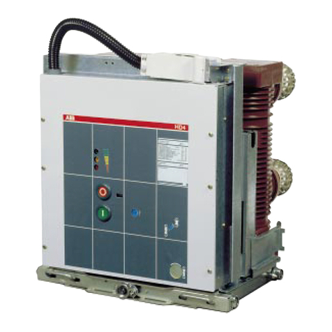
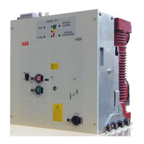
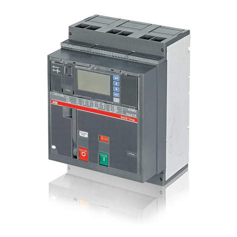
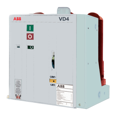
ABB VD4/R User manual

VD4/R - VD4/L - VD4/UniAir - VD4/UniMix
Installation and maintenance instructions
12 ... 24 kV - 630 ... 1250 A - 12 ... 25 kA

1

1
For your safety!
Make sure that the installation room (spaces, divisions and ambient) is suitable for the electrical apparatus.
Check that all the installation, putting into service and maintenance operations are carried out by qualified personnel
with suitable knowledge of the apparatus.
Make sure that the standard and legal prescriptions are complied with during installation, putting into service and
maintenance, so that installations according to the rules of good working practice and safety in the work place are
constructed.
Strictly follow the information given in this instruction manual.
Check that the rated performance of the apparatus is not exceeded during service.
Check that the personnel operating the apparatus have this instruction manual to hand as well as the necessary
information for correct intervention.
Pay special attention to the danger notes indicated in the manual by the following symbol:
Responsible behaviour safeguards your own and others’ safety!
For any requests, place contact the ABB Assistance Service.
Index
I. Introduction 2
II. Programme for environmental protection 2
1. Packing and transport 2
2. Checking on receipt 2
3. Storage 3
4. Handling 4
5. Description 5
5.1. General information 5
5.2. Reference Standards 5
5.3. Fixed circuit-breakers 5
5.4. Circuit-breakers for ABB switchgear 9
5.5. Characteristics of the electrical accessories 16
6. Instructions for circuit-breaker operation 17
6.1. Safety indications 17
6.2. Switching and signalling parts 17
6.3. Circuit-breaker closing and opening operations 17
7. Installation 18
7.1. General 18
7.2. Installation and operating conditions 18
7.3. Preliminary operations 19
7.4. Installation of fixed circuit-breakers 19
7.5. Installation of circuit-breakers for ABB switchgear 19
7.6. Connections of the power circuit 19
7.7. Earthing 20
7.8. Connection of the auxiliary circuits 20
8. Putting into service 21
8.1. General procedures 21
9. Maintenance 22
9.1. General 22
9.2. Inspections and functionality tests 22
9.3. Overhauling 22
9.4. Repairs 24
10. Application of the standards for X-ray emission 25
11. Spare parts and accessories 25
11.1. List of spare parts 25
12. Overall dimensions 26

2
Fig. 1
Caption
A Circuit-breaker rating plate.
B Operating mechanism rating plate.
1 Type of apparatus.
2 Symbols of compliance with Standards.
3 Serial number.
4 Circuit-breaker characteristics.
5 Characteristics of the operating mechanism auxiliaries.
I. Introduction
This publication contains the information needed to install and put the
following medium voltage circuit-breakers into service:
VD4/R - VD4/L - VD4/UniAir - VD4/UniMix, and VD4/S, hereinafter called
VD4.
For correct use of the product, please read it carefully.
Like all the apparatus we manufacture, the VD4 circuit-breakers are
also designed for different installation configurations.
However, this apparatus allows further technical-construction modifica-
tions (at the customer’s request) to adapt to special installation require-
ments. Consequently, the information given below may sometimes not
contain instructions concerning special configurations.
Apart from this manual, it is therefore always necessary to consult the
latest technical documentation (electric circuit and wiring diagrams, as-
sembly and installation drawings, any protection coordination studies,
etc.), especially regarding any variants requested in relation to the
standardised configurations.
Only use original spare parts for maintenance operations.
For further information, please also see the technical catalogue of the
circuit-breaker and the spare parts catalogue.
All the installation, putting into service, running and main-
tenance operations must be carried out by suitably quali-
fied personnel
with in-depth knowledge of the apparatus.
II. Environmental protection programme
The VD4 circuit-breakers are manufactured in accordance with the ISO
14000 Standards (Guidelines for environmental management).
The production processes are carried out in compliance with the Stan-
dards for environmental protection in terms of reduction in energy con-
sumption as well as in raw materials and production of waste materials.
All this is thanks to the medium voltage apparatus manufacturing facility
environmental management system.
A
B
3
4
2
CIRCUIT-BREAKER IEC 62271-100
VD4 ... ... ... CEI 17-1
CLASSIFICATION ... ... ...
SN ... ... ... PR. YEAR ......
M MASS ... kV
Ur
ELECTRIC DIAGRAM ... ... ... ...
FIG. ... ...
.. ... ... ... OPERATING MECHANISM
-MO1 ... ... ... V
Made by ABB
1
5
1. Packing and transport
The circuit-breaker is shipped in special packing, in the open position
and with the springs discharged.
Each piece of apparatus is protected by a plastic cover to prevent any
infiltration of water during the loading and unloading stages and to keep
the dust off during storage.
2. Checking on receipt
Before carrying out any operation, always make sure that
the operating mechanism springs are discharged and that
the apparatus is in the open position.
On receipt, check the state of the apparatus, integrity of the packing and
correspondence with the nameplate data (see fig. 1) with what is speci-
fied in the order confirmation and in the accompanying shipping note.
Also make sure that all the materials described in the shipping note are
included in the supply.
Should any damage or irregularity be noted in the supply on unpacking,
notify ABB (directly or through the agent or supplier) as soon as pos-
sible and in any case within five days of receipt.
The apparatus is only supplied with the accessories specified at the
time of ordering and validated in the order confirmation sent by ABB.
The accompanying documents inserted in the shipping packing are:
– instruction manual (this document)
– test certification
– identification label
– copy of the shipping documents
– electric wiring diagram.
Other documents which are sent prior to shipment of the apparatus are:
– order confirmation
– original shipping advice note
– any drawings or documents referring to special configurations/condi-
tions.
3
1
4. Handling
Before carrying out any operations, always make sure that the operat-
ing mechanism springs are discharged and that the apparatus is in the
open position.
To lift and handle the circuit-breaker, proceed as follows (fig. 2):
– use special lifting ropes with safety hooks;
– insert the hooks in the supports (1) fixed to the frame of the circuit-
breaker and lift.
– on completion of the operation (and in any case before putting into
service) release the lifting tool and dismantle the supports (1) from
the frame.
During handling, take great care not to stress the insulating parts and
the terminals of the circuit-breaker.
The apparatus must not be handled by putting lifting de-
vices directly under the apparatus itself. Should it be
necessary to use this technique, put the circuit-breaker
onto a pallet or a sturdy supporting surface (see fig. 3).
In any case, it is always advisable to carry out lifting using
the supports (3).
3. Storage
When a period of storage is foreseen, our workshops can (on request)
provide suitable packing for the specified storage conditions.
On receipt the apparatus must be carefully unpacked and checked as
described in Checking on receipt (chap. 2).
If immediate installation is not possible, the packing must be replaced,
using the original material supplied.
Insert packets of special hygroscopic substances inside the packing,
with at least one standard packet per piece of apparatus.
Should the original packing not be available and immediate installation is
not possible, store in a covered, well-ventilated, dry, dust-free, non-
corrosive ambient, away from any easily flammable materials and at a
temperature between –5 °C and +40 °C.
In any case, avoid any accidental impacts or positioning which stresses
the structure of the apparatus.
Fig. 2
Fig. 3

4
4
8
3
10
5
26
17
9
11
5. Description
5.1. General
The VD4 series of circuit-breakers are pieces of apparatus under vacuum
for indoor installation. For the electrical performances, please refer to
the corresponding technical catalogue code 1VCP000263.
For special installation requirements, please contact ABB.
The VD4 series of medium voltage vacuum circuit-breakers for indoor
installation with lateral operating mechanism are constructed using the
separate pole technique.
Each pole has a vacuum interrupter inside it which, thanks to a special
production process, is incorporated in the resin directly during the cylin-
der moulding stage.
This construction technique ensures protection of the vacuum inter-
rupter against impact, dust and condensation phenomena.
The operating mechanism is the EL type with stored energy and free
release, with opening and closing operations independent of the opera-
tor. The EL operating mechanism is already widely used in all the VD4
series circuit-breakers with front operating mechanism.
Remote control of the circuit-breaker is possible by means of applying
special electrical accessories (geared motor, shunt opening and shunt
closing release, etc.).
The operating mechanism, the three poles and the current sensors (if
provided) are mounted on a metallic frame without wheels. Construction
is particularly compact, sturdy and of limited weight.
The circuit-breakers in the VD4/R series with lateral operating mecha-
nism are “sealed for life” pressure systems (IEC 62271-100 and CEI
17-1 Standards).
Versions available
VD4 circuit-breakers with lateral operating mechanism are available in
the following versions:
– fixed with right lateral operating mechanism and 230 mm pole centre
distance
– fixed with left lateral operating mechanism and 230 mm pole centre
distance
– fixed with right lateral operating mechanism and 300 mm pole centre
distance
– fixed with left lateral operating mechanism and 300 mm pole centre
distance
– with right lateral operating mechanism, version for UniSwitch
switchgear, 210 mm pole centre distance
– with right lateral operating mechanism, version for UniMix, switchgear,
230 mm pole centre distance
– with right lateral operating mechanism, version for UniAir, switchgear,
300 mm pole centre distance.
On request and according to the version, they can be fitted with two or
three current sensors and with the PR521 series overcurrent protection
device.
5.2. Reference Standards
The VD4 circuit-breakers conform to the IEC 62271-100, CEI 17-1 file
1375 Standards and those of major industrialised countries.
5.3. Fixed circuit-breakers
The fixed circuit-breaker (fig. 4) is the basic version complete with struc-
ture and front protection screen. There are two drilled supports in the
lower part of the structure to allow circuit-breaker fixing.
The terminal box (10) is available for the electrical connections of the
circuit-breaker auxiliary circuits,.
The earthing screw is placed in the rear part of the circuit-breaker. For
further details please see the caption to figure 4.
Fig. 4
Caption
1 Lever for manual closing spring charging
2 Signalling device for circuit-breaker open/closed
3 Rating plate
4 Opening pushbutton
5 Closing pushbutton
6 Signalling device for closing springs charged/discharged
7 Operation counter
8 Terminals
9 Earthing screw
10 Delivery terminal box
11 Key lock (circuit-breaker open)

5
VD4/R 12
12
12
28
75
50-60
630 800 1250
12.5 — —
16 16 16
20 20 20
25 25 25
12.5 — —
16 16 16
20 20 20
25 25 25
31.5 — —
40 40 40
50 50 50
63 63 63
40…60
10...15
50…75
50...70
785
317
1029 (1) / 1170 (2)
230 / 300
65 (1) - 67 (2)
40 - 80 - 250 - 1250 (4)
(5)
1VCD000100 (1)
1VCD000101 (2)
1VCD400097
- 5 ... + 40
VD4/R 17
17.5
17.5
38
95
50-60
630 800 1250
12.5 — —
16 16 16
20 20 20
25 25 25
12.5 — —
16 16 16
20 20 20
25 25 25
31.5 — —
40 40 40
50 50 50
63 63 63
40…60
10...15
50…75
50...70
785
317
1029 (1) / 1170 (2)
230 / 300
65 (1) - 67 (2)
40 - 80 - 250 - 1250 (4)
(5)
1VCD000100 (1)
1VCD000101 (2)
1VCD400097
- 5 ... + 40
VD4/R 24
24
24
50
125
50-60
630 800 1250
12.5 — —
16 16 16
20 20 20
———
12.5 — —
16 16 16
20 20 20
———
31.5 — —
40 40 40
50 50 50
———
40…60
10...15
50…75
50...70
785
317
1029 (1) / 1170 (2)
230 / 300
65 (1) - 67 (2)
40 - 80 - 250 - 1250 (4)
(5)
1VCD000100 (1)
1VCD000101 (2)
1VCD400097
- 5 ... + 40
Circuit-breaker
Standards IEC 62271-100
CEI 17-1 (file 1375)
Rated voltage Ur [kV]
Rated insulation voltage Us [kV]
Withstand voltage at 50 Hz Ud (1 min) [kV]
Impulse withstand voltage Up [kV]
Rated frequency fr [Hz]
Rated normal current (40°C) Ir [A]
Rated breaking capacity Isc [kA]
(rated symmetrical short-circuit current)
Rated short-time withstand Ik [kA]
current (3s)
Making capacity Ip [kA]
Operation sequence [ O - 0.3s - CO - 15s - CO ]
Opening time [ms]
Arcing time [ms]
Total breaking time [ms]
Closing time [ms]
Overall H[mm]
dimensions W[mm]
(maximum) D [mm]
Pole centre distance I[mm]
Weight (3) [kg]
Application of PR521 protection device In [A]
Application of PR521/DK protection device
Table of standardised dimensions
Electric circuit diagram
Operating temperature [°C]
Tropicalization IEC: 60068-2-30, 60721-2-1
Electromagnetic compatibility IEC 60694
5.3.1. General characteristics of fixed circuit-breakers with right
lateral operating mechanism (12 – 17.5 – 24 kV)
(1) Pole centre distance: 230 mm
(2) Pole centre distance: 300 mm
(3) For circuit-breakers with PR 521 device and 3 current sensors, increase the weight indicated by 20 kg
(4) Rated current of the current sensors (the PR521 device and the current sensors are optional)
(5) DK type phase current sensors on board the circuit-breaker and toroidal CT for DK type homopolar protection not on board (the PR521/DK device and the DK sensors are
optional)
W
H
D

6
5.3.2. General characteristics of fixed circuit-breakers with left lateral operating mechanism (12 – 17.5 – 24 kV)
(1) Pole centre distance: 230 mm
(2) Pole centre distance: 300 mm
(3) For circuit-breakers with PR 521 device and 3 current sensors, increase the weight indicated by 20 kg
(4) Rated current of the current sensors (the PR521 device and the current sensors are optional)
(5) DK type phase current sensors on board the circuit-breaker and toroidal CT for DK type homopolar protection not on board (the PR521/DK device and the DK
sensors are optional)
VD4/L 12
12
12
28
75
50-60
630 800 1250
12.5 — —
16 16 16
20 20 20
25 25 25
12.5 — —
16 16 16
20 20 20
25 25 25
31.5 — —
40 40 40
50 50 50
63 63 63
40…60
10...15
50…75
50...70
785
317
1029 (1) / 1170 (2)
230 / 300
65 (1) - 67 (2)
40 - 80 - 250 - 1250 (4)
(5)
1VCD003453 (1)
1VCD003454 (2)
1VCD400097
- 5 ... + 40
VD4/L 17
17.5
17.5
38
95
50-60
630 800 1250
12.5 — —
16 16 16
20 20 20
25 25 25
12.5 — —
16 16 16
20 20 20
25 25 25
31.5 — —
40 40 40
50 50 50
63 63 63
40…60
10...15
50…75
50...70
785
317
1029 (1) / 1170 (2)
230 / 300
65 (1) - 67 (2)
40 - 80 - 250 - 1250 (4)
(5)
1VCD003453 (1)
1VCD003454 (2)
1VCD400097
- 5 ... + 40
VD4/L 24
24
24
50
125
50-60
630 800 1250
12.5 —- —-
16 16 16
20 20 20
——- —-
12.5 —- —-
16 16 16
20 20 20
——- —-
31.5 —- —-
40 40 40
50 50 50
——- —-
40…60
10...15
50…75
50...70
785
317
1029 (1) / 1170 (2)
230 / 300
65 (1) - 67 (2)
40 - 80 - 250 - 1250 (4)
(5)
1VCD003453 (1)
1VCD003454 (2)
1VCD400097
- 5 ... + 40
W
H
D
Circuit-breaker
Standards IEC 62271-100
CEI 17-1 (file 1375)
Rated voltage Ur [kV]
Rated insulation voltage Us [kV]
Withstand voltage at 50 Hz Ud (1 min) [kV]
Impulse withstand voltage Up [kV]
Rated frequency fr [Hz]
Rated normal current (40°C) Ir [A]
Rated breaking capacity Isc [kA]
(rated symmetrical short-circuit current)
Rated short-time withstand Ik [kA]
current (3s)
Making capacity Ip [kA]
Operation sequence [ O - 0.3s - CO - 15s - CO ]
Opening time [ms]
Arcing time [ms]
Total breaking time [ms]
Closing time [ms]
Overall H[mm]
dimensions W[mm]
(maximum) D [mm]
Pole centre distance I[mm]
Weight (3) [kg]
Application of PR521 protection device In [A]
Application of PR521/DK protection device
Table of standardised dimensions
Electric circuit diagram
Operating temperature [°C]
Tropicalization IEC: 60068-2-30, 60721-2-1
Electromagnetic compatibility IEC 60694

7
Pole centre distance Technical documentation
U [kV] In [A] Isc [kA] Description 230 mm 300 mm Dimensions Electric diagram
12 630 12.5 VD4/R 12.06.12
16 VD4/R 12.06.16
20 VD4/R 12.06.20
25 VD4/R 12.06.25
800 16 VD4/R 12.08.16
20 VD4/R 12.08.20
25 VD4/R 12.08.25
1250 16 VD4/R 12.12.16
20 VD4/R 12.12.20
25 VD4/R 12.12.25
17.5 630 12.5 VD4/R 17.06.12
16 VD4/R 17.06.16
20 VD4/R 17.06.20
25 VD4/R 17.06.25
800 16 VD4/R 17.08.16
20 VD4/R 17.08.20
25 VD4/R 17.08.25
1250 16 VD4/R 17.12.16
20 VD4/R 17.12.20
25 VD4/R 17.12.25
24 630 12.5 VD4/R 24.06.12
16 VD4/R 24.06.16
20 VD4/R 24.06.20
800 16 VD4/R 24.08.16
20 VD4/R 24.08.20
1250 16 VD4/R 24.12.16
20 VD4/R 24.12.20
1VCD000100
(230 mm);
1VCD000101
(300 mm)
1VCD000100
(230 mm);
1VCD000101
(300 mm)
1VCD400097
1VCD400097
1VCD000100
(230 mm);
1VCD000101
(300 mm)
1VCD400097
5.3.3. Types available of fixed circuit-breakers VD4/R 12-17-24 (right lateral operating mechanism)

8
Pole centre distance Technical documentation
U [kV] In [A] Isc [kA] Description 230 mm 300 mm Dimensions Electric diagram
12 630 12.5 VD4/L 12.06.12
16 VD4/L 12.06.16
20 VD4/L 12.06.20
25 VD4/L 12.06.25
800 16 VD4/L 12.08.16
20 VD4/L 12.08.20
25 VD4/L 12.08.25
1250 16 VD4/L 12.12.16
20 VD4/L 12.12.20
25 VD4/L 12.12.25
17.5 630 12.5 VD4/L 17.06.12
16 VD4/L 17.06.16
20 VD4/L 17.06.20
25 VD4/L 17.06.25
800 16 VD4/L 17.08.16
20 VD4/L 17.08.20
25 VD4/L 17.08.25
1250 16 VD4/L 17.12.16
20 VD4/L 17.12.20
25 VD4/L 17.12.25
24 630 12.5 VD4/L 24.06.12
16 VD4/L 24.06.16
20 VD4/L 24.06.20
800 16 VD4/L 24.08.16
20 VD4/L 24.08.20
1250 16 VD4/L 24.12.16
20 VD4/L 24.12.20
1VCD003453
(230 mm)
1VCD003454
(300 mm)
1VCD003453
(230 mm)
1VCD003454
(300 mm)
1VCD400097
1VCD400097
1VCD003453
(230 mm)
1VCD003454
(300 mm)
1VCD400097
VD4/L 12-17-24 (left lateral operating mechanism)
The basic cabling ends at a terminal box. The terminal box is fitted with
a removable part which allows the customer to make a disconnectable
power cord (see images at the side).
The basic version also includes the following accessories to be specified
at the time of ordering: (see Kits 1, 2, 3).
Kit 1 set of five open/closed auxiliary contacts or, alternatively and on
payment, ten or fifteen auxiliary contacts. Each shunt opening
release uses one NO auxiliary contact to de-energise after having
opened the circuit-breaker, therefore there is one NO auxiliary
contact less
Kit 2 shunt opening release.
Kit 3 key lock.
Standard fittings for fixed circuit-breakers
VD4/R fixed circuit-breakers with right lateral operating mechanism
(230 or 300 mm centre distance) and VD4/L fixed circuit-breakers with
left lateral operating mechanism (230 or 300 mm centre distance)
The basic coded version of the fixed circuit-breakers is always three-
pole and is fitted with:
1opening pushbutton
2closing pushbutton
3operation counter
4mechanical signalling device for circuit-breaker open/closed
5lever for manual spring charging (incorporated in the operating
mechanism)
6mechanical signalling device for closing springs charged/
discharged.

9
1 1 1
1
2
3
1
2
4
Caption
1 Isolating contacts
2 Wheels
3 Release lever
4 Connector
Fig. 5
Standard fittings for ABB switchgear circuit-breaker
1. Circuit-breakers for UniSwitch switchgear with right
lateral operating mechanism (centre distance 210 mm)
The basic coded version of the VD4/S circuit-breakers for UniSwitch
switchgear is the same as that of the fixed circuit-breakers with the
following exceptions and specific fittings:
– base fitted with wheels to facilitate handling and racking into the
compartment of the UniSwitch switchgear,
– top and bottom terminals prepared for connection to the busbars of
the UniSwitch switchgear
– insulating caps to be installed on the upper part of the poles (after
having connected the busbars to the top terminals)
– special connector (58-pole male socket) fixed onto the right side of
the operating mechanism casing. The connector is fitted with a lock
which does not allow manual operation unless the plug fitted with the
special insulating release pin is inserted
– insulating release pin to be inserted in the plug (58-pole female) to
disable the lock which does not allow manual operation unless the
plug is inserted in the socket on the operating mechanism.
On request and on payment, a set of 12 auxiliary contacts is available,
alternatively to the group of 5 open/closed auxiliary contacts. Each shunt
opening release uses one NO auxiliary contact to de-energise after
having carried out circuit-breaker opening, therefore for each shunt
opening release installed there is one NO auxiliary contact less available.
2. Circuit-breakers for switchgear UniMix with right lateral
operating mechanism (centre distance 230 mm)
The basic coded version of the circuit-breakers for UniSwitch switchgear
is the same as that of the fixed circuit-breakers.The operating mechanism
casing is fitted with a side frame specific to the UniMix unit which the
circuit-breaker must be racked into. In particular:
– type VD4/UniMix-F has the top and bottom terminals prepared for
connection to the busbars of the UniMix switchgear P1/F unit.
Alternatively and on payment, 10 or 15 auxiliary contacts are available.
Each shunt opening release uses one NO auxiliary contact to de-
energise after having carried out circuit-breaker opening, therefore
for each shunt opening release installed there is one NO auxiliary
contact less available
– type VD4/UniMix-R has a base fitted with wheels to facilitate handling
and racking into the switchgear compartment, a power cord with 58-
pole plug for the auxiliary circuits, and the top and bottom terminals
prepared for connection to the busbars of the UniMix switchgear P1/
F unit. Alternatively and on payment, 12 auxiliary contacts are available.
Each shunt opening release uses one NO auxiliary contact to de-
energise after having carried out circuit-breaker opening, therefore
for each shunt opening release installed there is one NO auxiliary
contact less available.
3. Circuit-breakers for switchgear UniAir with right lateral
operating mechanism (centre distance 300 mm)
The basic coded version of the circuit-breakers for UniAir switchgear is
the same as the one for the fixed circuit-breakers. The operating
mechanism casing is fitted with a side frame specific to the UniAir unit
which the circuit-breaker must be racked into. In particular:
– type VD4/UniAir has the base fitted with wheels to facilitate handling
and racking into the switchgear compartment, a power cord with 58-
pole plug for the auxiliary circuits, the top and bottom terminals pre-
pared with flat contacts for connection to the isolator on the supply
side and to the busbars (or DIN CT) on the load side of the UniAir
switchgear P1/E unit, and the release lever which keeps the circuit-
breaker locked in the unit.
Alternatively and on payment, 12 auxiliary contacts are available.
Each shunt opening release uses one NO auxiliary contact to de-
energise after having carried out circuit-breaker opening, therefore
for each shunt opening release installed there is one NO auxiliary
contact less available
– type VD4/UniAir-2R has the base fitted with wheels to facilitate han-
dling and racking into the switchgear compartment, a power cord with
58-pole plug for the auxiliary circuits and the top and bottom terminals
prepared with pliers for connection to the isolator on the supply and
load side of the UniAir switchgear P1E/2R unit, and the release lever
which keeps the circuit-breaker locked in the unit. Alternatively and
on payment, 12 auxiliary contacts are available. Each shunt opening
release uses one NO auxiliary contact to de-energise after having
carried out circuit-breaker opening, therefore for each shunt opening
release installed there is one NO auxiliary contact less available
– type VD4/UniAir-A has the base fitted with wheels to facilitate handling
and racking into the switchgear compartment, a power cord with 58-
pole plug for the auxiliary circuits, the top fixed terminals and the
bottom terminals are prepared with pliers for connection to the
busbars/CT on the supply side and to the isolator on the load side of
the UniAir switchgear P1/A unit, and the release lever which keeps
the circuit-breaker locked in the unit. Alternatively and on payment, 12
auxiliary contacts are available. Each shunt opening release uses a
NO auxiliary contact to de-energise after having carried out circuit-
breaker opening, therefore for each shunt opening release installed
there is one NO auxiliary contact less available
– type VD4/UniAir-F is without wheels and power cord and only has the
fixed bottom and top terminals prepared with pliers for connection to
the busbars/CT on the load side of the UniAir switchgear P1/F unit.
Alternatively and on payment, 10 or 15 auxiliary contacts are avail-
able. Each shunt opening release uses one NO auxiliary contact for
de-energise after having carried out circuit-breaker opening, there-
fore for each shunt opening release installed there is one NO auxiliary
contact less available.
5.4. Circuit-breakers for ABB switchgear
Circuit-breakers (see fig. 5) available for UniSwitch, UniAir and UniMix
switchgear.
They are basically derived from a fixed circuit-breaker to which the
wheels, isolating contacts, locking lever and connector are applied.

10
General characteristics of circuit-breakers with right lateral operating mechanism for
ABB UniSwitch type switchgear (12 – 17.5 – 24 kV)
VD4/S 12
12
12
28
75
50-60
630 800 1250
12.5 12.5 12.5
16 16 16
20 20 20
25 25 25
12.5 12.5 12.5
16 16 16
20 20 20
25 25 25
31.5 31.5 31.5
40 40 40
50 50 50
63 63 63
40…60
10...15
50…75
50...70
730
282
990
210
67
40 - 80 - 250 - 1250 (2)
see note (3)
1VCD000098
1VCD400098
- 5 ... + 40
VD4/S 17
17.5
17.5
38
95
50-60
630 800 1250
12.5 12.5 12.5
16 16 16
20 20 20
———
12.5 12.5 12.5
16 16 16
20 20 20
———
31.5 31.5 31.5
40 40 40
50 50 50
———
40…60
10...15
50…75
50...70
730
282
990
210
67
40 - 80 - 250 - 1250 (2)
see note (3)
1VCD000098
1VCD400098
- 5 ... + 40
VD4/S 24
24
24
50
125
50-60
630 800 1250
12.5 12.5 12.5
16 16 16
20 20 20
———
12.5 12.5 12.5
16 16 16
20 20 20
———
31.5 31.5 31.5
40 40 40
50 50 50
———
40…60
10...15
50…75
50...70
730
282
990
210
67
40 - 80 - 250 - 1250 (2)
see note (3)
1VCD000098
1VCD400098
- 5 ... + 40
W
H
D
(1) For circuit-breakers with PR 521 device and 3 current sensors, increase the weight indicated by 20 kg
(2) Rated current of the current sensors (the PR521 device and the current sensors are optional)
(3) Special version with “ß = 1” or “ß = 1, RI” curves for the Belgian market: please ask ABB for availability and delivery times
Circuit-breaker
Standards IEC 62271-100
CEI 17-1 (file 1375)
Rated voltage Ur [kV]
Rated insulation voltage Us [kV]
Withstand voltage at 50 Hz Ud (1 min) [kV]
Impulse withstand voltage Up [kV]
Rated frequency fr [Hz]
Rated normal current (40°C) Ir [A]
Rated breaking capacity Isc [kA]
(rated symmetrical short-circuit current)
Rated short-time withstand Ik [kA]
current (3s)
Making capacity Ip [kA]
Operation sequence [ O - 0.3s - CO - 15s - CO ]
Opening time [ms]
Arcing time [ms]
Total breaking time [ms]
Closing time [ms]
Overall H[mm]
dimensions W[mm]
(maximum) D [mm]
Pole centre distance I[mm]
Weight
(3)
[kg]
Application of PR521 protection device In [A]
Application of PR521/DK protection device
Table of standardised dimensions
Electric circuit diagram
Operating temperature [°C]
Tropicalization IEC: 60068-2-30, 60721-2-1
Electromagnetic compatibility IEC 60694

11
General characteristics of circuit-breakers with right lateral operating mechanism for
UniMix type switchgear (12 – 17.5 – 24 kV)
VD4/UniMix 12
12
12
28
75
50-60
630
12.5
16
20
25
12.5
16
20
25
31.5
40
50
63
40…60
10...15
50…75
50...70
700 (4) - 734 (5)
382 (IP30) - 393 (A.I.)
1030
230
65
40 - 80 - 250 - 1250 (2)
(3)
1VCD000106 (4)
1VCD000107 (5)
1VCD400097 (4)
1VCD400098 (5)
- 5 ... + 40
VD4/UniMix 17
17.5
17.5
38
95
50-60
630
12.5
16
20
25
12.5
16
20
25
31.5
40
50
63
40…60
10...15
50…75
50...70
700 (4) - 734 (5)
382 (IP30) - 393 (A.I.)
1030
230
65
40 - 80 - 250 - 1250 (2)
(3)
1VCD000106 (4)
1VCD000107 (5)
1VCD400097 (4)
1VCD400098 (5)
- 5 ... + 40
VD4/UniMix 24
24
24
50
125
50-60
630
12.5
16
20
—
12.5
16
20
—
31.5
40
50
—
40…60
10...15
50…75
50...70
700 (4) - 734 (5)
382 (IP30) - 393 (A.I.)
1030
230
65
40 - 80 - 250 - 1250 (2)
(3)
1VCD000106 (4)
1VCD000107 (5)
1VCD400097 (4)
1VCD400098 (5)
- 5 ... + 40
(1) For circuit-breakers with PR 521 device and 3 current sensors, increase the weight indicated by 20 kg
(2) Rated current of the current sensors (the PR521 device and the current sensors are optional)
(3) DK type phase current sensors on board the circuit-breaker and DK type toroidal CT not on board (the PR521/DK device and the DK sensors are optional)
(4) VD4/UniMix-F for P1/F Unit (fixed circuit-breaker without wheels and cabled to terminal box)
(5) VD4/UniMix-R for P1/F Unit (fixed circuit-breaker with wheels and power cord with plug)
H
Circuit-breaker
Standards IEC 62271-100
CEI 17-1 (file 1375)
Rated voltage Ur [kV]
Rated insulation voltage Us [kV]
Withstand voltage at 50 Hz Ud (1 min) [kV]
Impulse withstand voltage Up [kV]
Rated frequency fr [Hz]
Rated normal current (40°C) Ir [A]
Rated breaking capacity Isc [kA]
(rated symmetrical short-circuit current)
Rated short-time withstand Ik [kA]
current (3s)
Making capacity Ip [kA]
Operation sequence [ O - 0.3s - CO - 15s - CO ]
Opening time [ms]
Arcing time [ms]
Total breaking time [ms]
Closing time [ms]
Overall H[mm]
dimensions W[mm]
(maximum) D [mm]
Pole centre distance I[mm]
Weight (3) [kg]
Application of PR521 protection device In [A]
Application of PR521/DK protection device
Table of standardised dimensions
Electric circuit diagram
Operating temperature [°C]
Tropicalization IEC: 60068-2-30, 60721-2-1
Electromagnetic compatibility IEC 60694
W
D

12
General characteristics of circuit-breakers with right lateral operating mechanism for
IP30 UniAir type switchgear (12 – 17.5 – 24 kV)
VD4/UniAir 12
12
12
28
75
50-60
630 800 1250
12.5 — —
16 16 16
20 20 20
25 25 25
12.5 — —
16 16 16
20 20 20
25 25 25
31.5 — —
40 40 40
50 50 50
63 63 63
40…60
10...15
50…75
50...70
734.5 (4) (5) (6) - 725 (7)
374 (4) (5) (6) - 282 (7)
1170 (4) (5) (6) (7)
300
70 (4) (5) (6) - 67 (7)
40 - 80 - 250 - 1250 (2)
(3)
1VCD000102 (4)
1VCD000103 (5)
1VCD000104 (6)
1VCD000105 (7)
1VCD400098 (4) (5) (6)
1VCD400097 (7)
- 5 ... + 40
VD4/UniAir 17
17.5
17.5
38
95
50-60
630 800 1250
12.5 — —
16 16 16
20 20 20
25 — —
12.5 — —
16 16 16
20 20 20
25 — —
31.5 — —
40 40 40
50 50 50
63 — —
40…60
10...15
50…75
50...70
734.5 (4) (5) (6) - 725 (7)
374 (4) (5) (6) - 282 (7)
1170 (4) (5) (6) (7)
300
70 (4) (5) (6) - 67 (7)
40 - 80 - 250 - 1250 (2)
(3)
1VCD000102 (4)
1VCD000103 (5)
1VCD000104 (6)
1VCD000105 (7)
1VCD400098 (4) (5) (6)
1VCD400097 (7)
- 5 ... + 40
VD4/UniAir 24
24
24
50
125
50-60
630 800 1250
12.5 —- —-
16 16 16
20 20 20
——- —-
12.5 —- —-
16 16 16
20 20 20
——- —-
31.5 —- —-
40 40 40
50 50 50
——- —-
40…60
10...15
50…75
50...70
734.5 (4) (5) (6) - 725 (7)
374 (4) (5) (6) - 282 (7)
1170 (4) (5) (6) (7)
300
70 (4) (5) (6) - 67 (7)
40 - 80 - 250 - 1250 (2)
(3)
1VCD000102 (4)
1VCD000103 (5)
1VCD000104 (6)
1VCD000105 (7)
1VCD400098 (4) (5) (6)
1VCD400097 (7)
- 5 ... + 40
W
H
D
(1) For circuit-breakers with PR 521 device and 3 current sensors, increase the weight indicated by 20 kg
(2) Rated current of the current sensors (the PR521 device and the current sensors are optional)
(3) DK type phase current sensors on board the circuit-breaker and toroidal CT for DK type homopolar protection not on board (the PR521/DK device and the DK sensors are
optional)
(4) VD4/UniAir for P1/E Unit IP30 version (unit with plug-in circuit-breaker); the circuit-breaker for the same Arc Proof version unit is not available
(5) VD4/UniAir-2R for P1E/2R Unit IP30 version (unit with withdrawable circuit-breaker on supply and load side); the circuit-breaker for the same Arc Proof version unit is not
available
(6) VD4/UniAir-A for P1/A Unit IP30 version (unit with fixed “upside-down” circuit-breaker); the circuit-breaker for the same Arc Proof version unit is not available
(7) VD4/UniAir-F for P1/F Unit IP30 version (unit with fixed circuit-breaker without wheels and cabled to terminal box); the circuit-breaker for the same Arc Proof version unit
is not available
Circuit-breaker
Standards IEC 62271-100
CEI 17-1 (file 1375)
Rated voltage Ur [kV]
Rated insulation voltage Us [kV]
Withstand voltage at 50 Hz Ud (1 min) [kV]
Impulse withstand voltage Up [kV]
Rated frequency fr [Hz]
Rated normal current (40°C) Ir [A]
Rated breaking capacity Isc [kA]
(rated symmetrical short-circuit current)
Rated short-time withstand Ik [kA]
current (3s)
Making capacity Ip [kA]
Operation sequence [ O - 0.3s - CO - 15s - CO ]
Opening time [ms]
Arcing time [ms]
Total breaking time [ms]
Closing time [ms]
Overall H[mm]
dimensions W[mm]
(maximum) D [mm]
Pole centre distance I[mm]
Weight
(3)
[kg]
Application of PR521 protection device In [A]
Application of PR521/DK protection device
Table of standardised dimensions
Electric circuit diagram
Operating temperature [°C]
Tropicalization IEC: 60068-2-30, 60721-2-1
Electromagnetic compatibility IEC 60694

13
5.4.2. Types available circuit-breakers for ABB switchgear
Pole centre distance Technical documentation
U [kV] In [A] Isc [kA] Description 230 mm Dimensions Electrical diagram
12 630 12.5 VD4/UniMix-F 12.06.12
16 VD4/UniMix-F 12.06.16
20 VD4/UniMix-F 12.06.20
25 VD4/UniMix-F 12.06.25
17.5 630 12.5 VD4/UniMix-F 17.06.12
16 VD4/UniMix-F 17.06.16
20 VD4/UniMix-F 17.06.20
25 VD4/UniMix-F 17.06.25
24 630 12.5 VD4/UniMix-F 24.06.12
16 VD4/UniMix-F 24.06.16
20 VD4/UniMix-F 24.06.20
VD4/UniMix-F 12-17-24 (right lateral operating mechanism; version for UniMix switchgear P1/F unit both IP30,
and Arc-proof; circuit-breaker without wheels and cabled to terminal box)
Pole centre distance Technical documentation
U [kV] In [A] Isc [kA] Description 210 mm Dimensions Electrical diagram
12 630 12.5 VD4/S 12.06.12
16 VD4/S 12.06.16
20 VD4/S 12.06.20
25 VD4/S 12.06.25
800 12.5 VD4/S 12.08.12
16 VD4/S 12.08.16
20 VD4/S 12.08.20
25 VD4/S 12.08.25
1250 12.5 VD4/S 12.12.12
16 VD4/S 12.12.16
20 VD4/S 12.12.20
25 VD4/S 12.12.25
17.5 630 12.5 VD4/S 17.06.12
16 VD4/S 17.06.16
20 VD4/S 17.06.20
800 12.5 VD4/S 17.08.12
16 VD4/S 17.08.16
20 VD4/S 17.08.20
1250 12.5 VD4/S 17.12.12
16 VD4/S 17.12.16
20 VD4/S 17.12.20
24 630 12.5 VD4/S 24.06.12
16 VD4/S 24.06.16
20 VD4/S 24.06.20
800 12.5 VD4/S 24.08.12
16 VD4/S 24.08.16
20 VD4/S 24.08.20
1250 12.5 VD4/S 24.12.12
16 VD4/S 24.12.16
20 VD4/S 24.12.20
VD4/S 12-17-24 (right lateral operating mechanism; version for UniSwitch switchgear)
1VCD4000971VCD000106
1VCD4000981VCD000098

14
Pole centre distance Technical documentation
U [kV] In [A] Isc [kA] Description 230 mm Dimensions Electrical diagram
12 630 12.5 VD4/UniMix-R 12.06.12
16 VD4/UniMix-R 12.06.16
20 VD4/UniMix-R 12.06.20
25 VD4/UniMix-R 12.06.25
17.5 630 12.5 VD4/UniMix-R 17.06.12
16 VD4/UniMix-R 17.06.16
20 VD4/UniMix-R 17.06.20
25 VD4/UniMix-R 17.06.25
24 630 12.5 VD4/UniMix-R 24.06.12
16 VD4/UniMix-R 24.06.16
20 VD4/UniMix-R 24.06.20
VD4/UniMix-R 12-17-24 (right lateral operating mechanism; version for UniMix switchgear P1/F unit both IP30,
and Arc-proof; circuit-breaker with wheels and fitted with power cord with 58-pole plug)
Pole centre distance Technical documentation
U [kV] In [A] Isc [kA] Description 300 mm Dimensions Electrical diagram
12 630 12.5 VD4/UniAir 12.06.12
16 VD4/UniAir 12.06.16
20 VD4/UniAir 12.06.20
25 VD4/UniAir 12.06.25
800 16 VD4/UniAir 12.08.16
20 VD4/UniAir 12.08.20
25 VD4/UniAir 12.08.25
1250 16 VD4/UniAir 12.12.16
20 VD4/UniAir 12.12.20
25 VD4/UniAir 12.12.25
17.5 630 12.5 VD4/UniAir 17.06.12
16 VD4/UniAir 17.06.16
20 VD4/UniAir 17.06.20
800 16 VD4/UniAir 17.08.16
20 VD4/UniAir 17.08.20
1250 16 VD4/UniAir 17.12.16
20 VD4/UniAir 17.12.20
24 630 12.5 VD4/UniAir 24.06.12
16 VD4/UniAir 24.06.16
20 VD4/UniAir 24.06.20
800 16 VD4/UniAir 24.08.16
20 VD4/UniAir 24.08.20
1250 16 VD4/UniAir 24.12.16
20 VD4/UniAir 24.12.20
VD4/UniAir 12-17-24 (right lateral operating mechanism; version for UniAir switchgear P1/E unit - IP30 version –
unit with circuit-breaker withdrawable on the supply side)
Pole centre distance Technical documentation
U [kV] In [A] Isc [kA] Description 300 mm Dimensions Electrical diagram
12 630 12.5 VD4/UniAir-2R 12.06.12
16 VD4/UniAir-2R 12.06.16
20 VD4/UniAir-2R 12.06.20
25 VD4/UniAir-2R 12.06.25
800 16 VD4/UniAir-2R 12.08.16
20 VD4/UniAir-2R 12.08.20
25 VD4/UniAir-2R 12.08.25
1250 16 VD4/UniAir-2R 12.12.16
20 VD4/UniAir-2R 12.12.20
25 VD4/UniAir-2R 12.12.25
17.5 630 12.5 VD4/UniAir-2R 17.06.12
16 VD4/UniAir-2R 17.06.16
20 VD4/UniAir-2R 17.06.20
800 16 VD4/UniAir-2R 17.08.16
20 VD4/UniAir-2R 17.08.20
1250 16 VD4/UniAir-2R 17.12.16
20 VD4/UniAir-2R 17.12.20
24 630 12.5 VD4/UniAir-2R 24.06.12
16 VD4/UniAir-2R 24.06.16
20 VD4/UniAir-2R 24.06.20
800 16 VD4/UniAir-2R 24.08.16
20 VD4/UniAir-2R 24.08.20
1250 16 VD4/UniAir-2R 24.12.16
20 VD4/UniAir-2R 24.12.20
VD4/UniAir-2R 12-17-24 (right lateral operating mechanism; version for UniAir switchgear P1/E 2R unit - IP30
version – unit with circuit-breaker withdrawable on the supply and load side)
1VCD4000981VCD000107
1VCD4000981VCD000102
1VCD4000981VCD000103

15
Pole centre distance Technical documentation
U [kV] In [A] Isc [kA] Description 300 mm Dimensions Electrical diagram
12 630 12.5 VD4/UniAir-A 12.06.12
16 VD4/UniAir-A 12.06.16
20 VD4/UniAir-A 12.06.20
25 VD4/UniAir-A 12.06.25
800 16 VD4/UniAir-A 12.08.16
20 VD4/UniAir-A 12.08.20
25 VD4/UniAir-A 12.08.25
1250 16 VD4/UniAir-A 12.12.16
20 VD4/UniAir-A 12.12.20
25 VD4/UniAir-A 12.12.25
17.5 630 12.5 VD4/UniAir-A 17.06.12
16 VD4/UniAir-A 17.06.16
20 VD4/UniAir-A 17.06.20
800 16 VD4/UniAir-A 17.08.16
20 VD4/UniAir-A 17.08.20
1250 16 VD4/UniAir-A 17.12.16
20 VD4/UniAir-A 17.12.20
24 630 12.5 VD4/UniAir-A 24.06.12
16 VD4/UniAir-A 24.06.16
20 VD4/UniAir-A 24.06.20
800 16 VD4/UniAir-A 24.08.16
20 VD4/UniAir-A 24.08.20
1250 16 VD4/UniAir-A 24.12.16
20 VD4/UniAir-A 24.12.20
VD4/UniAir-A 12-17-24 (right lateral operating mechanism; version for UniAir switchgear P1/A unit - IP30 version
– unit “upside-down” with circuit-breaker withdrawable on the load side)
Pole centre distanceTechnical documentation
U [kV] In [A] Isc [kA] Description 300 mm Dimensions Electrical diagram
12 630 12.5 VD4/UniAir-F 12.06.12
16 VD4/UniAir-F 12.06.16
20 VD4/UniAir-F 12.06.20
25 VD4/UniAir-F 12.06.25
800 16 VD4/UniAir-F 12.08.16
20 VD4/UniAir-F 12.08.20
25 VD4/UniAir-F 12.08.25
1250 16 VD4/UniAir-F 12.12.16
20 VD4/UniAir-F 12.12.20
25 VD4/UniAir-F 12.12.25
17.5 630 12.5 VD4/UniAir-F 17.06.12
16 VD4/UniAir-F 17.06.16
20 VD4/UniAir-F 17.06.20
800 16 VD4/UniAir-F 17.08.16
20 VD4/UniAir-F 17.08.20
1250 16 VD4/UniAir-F 17.12.16
20 VD4/UniAir-F 17.12.20
24 630 12.5 VD4/UniAir-F 24.06.12
16 VD4/UniAir-F 24.06.16
20 VD4/UniAir-F 24.06.20
800 16 VD4/UniAir-F 24.08.16
20 VD4/UniAir-F 24.08.20
1250 16 VD4/UniAir-F 24.12.16
20 VD4/UniAir-F 24.12.20
VD4/UniAir-F 12-17-24 (right lateral operating mechanism; version for UniAir switchgear P1/F unit - IP30
version – unit with fixed circuit-breaker without wheels and cabled to terminal box)
1VCD4000981VCD000104
1VCD4000971VCD000105

16
5.5. Characteristics of the electrical accessories
Shunt opening release (-M01); Additional shunt opening release
(-M02); Shunt closing release (-MC)
Un: 24 - 30 - 48 - 60 - 110 - 125 - 220 - 250 V–
Un: 24 - 48 - 60 - 110 - 120 ... 127 - 220 ... 240 V~ 50 Hz
Un: 110 - 120 - 127 - 220 - 240 V~ 60 Hz
Operating limits: 70 … 110 % Un
Inrush power (Ps): DC 200 W; AC = 200 VA
Inrush time approx. 100 ms
Continuous power (Pc): DC = 5 W; AC = 5 VA
Opening time: 35 ... 60 ms
Closing time: 30 ... 80 ms
Insulation voltage: 2500 V 50 Hz (for 1 min)
Undervoltage release (-MU)
Un: 24 - 30 - 48 - 60 - 110 - 125 - 220 - 250 V–
Un: 24 - 48 - 60 - 110 - 120 - 127 - 220 ... 240 V~ 50 Hz
Un: 110 - 120 ... 127 - 220 ... 240 V~ 60 Hz
Operating limits:
– circuit-breaker opening: 35-70% Un
– circuit-breaker closing: 85-110% Un
Inrush power (Ps): DC 200 W; AC = 200 VA
Inrush time approx. 100 ms
Continuous power (Pc): DC = 5 W; AC = 5 VA
Opening time: 30 ms
Insulation voltage: 2500 V 50 Hz (for 1 min)
Summary of the total number of auxiliary contacts available (*)
(*) Each shunt opening release requested uses an auxiliary contact to de-energise after opening the circuit-breaker, therefore the number of auxiliary contacts actually
available is reduced by the same number of shunt opening releases installed.
Total number
VD4/R p230
VD4/R p300
VD4/L p230
VD4/L p300
VD4/UniMix-F p230
VD4/UniAir-F p230
VD4/S p210
VD4/UniMix-R p230
VD4/UniAir
VD4/UniAir-2R
VD4/UniAir-A p300
5 auxiliary contacts
(-BB1)
Standard fitting
Standard fitting
Standard fitting
Standard fitting
Standard fitting
Standard fitting
12 auxiliary contacts
(-BB1, -BB2, -BB3)
Alternative
not available
As above
As above
Alternative available on
request. It is the minimum
compulsory number if -M02
(the additional shunt
opening release) is also
requested
As above
As above
15 auxiliary contacts
(-BB1, -BB2, -BB3)
Alternative available
on request
As above
As above
Alternative
not available
As above
As above
10 auxiliary contacts
(-BB1, -BB2)
Alternative available on
request. It is the minimum
compulsory number if -M02
(the additional shunt
opening release) is also
requested
As above
As above
As above
As above
As above
Electronic time delay device for undervoltage release
(mounted outside the circuit-breaker)
Un: 24 ... 30 - 48 - 60 - 110 ... 127 - 220 ... 250 V–
Un: 48 - 60 - 110 ... 127 - 220 ... 240 V~ 50/60 Hz
Adjustable opening time
(release + time delay device): 0.5-1-1.5-2-3 s
Auxiliary contacts of the circuit-breaker
Un: 24 ... 250 V AC-DC
Rated current Ith2 = 10 A
Insulation voltage: 2500 V 50 Hz (for 1 min)
Electrical resistance: 3 mOhm
Rated current and breaking capacity in category AC11 and DC11:
Un Cosϕϕ
ϕϕ
ϕT In Icu
220 V ~ 0.7 -- 2.5 A 25 A
24 V – -- 15 ms 10 A 12 A
60 V – -- 15 ms 6 A 8 A
110 V – -- 15 ms 4 A 5 A
220 V – -- 15 ms 1 A 2 A
Motor operator (-MS)
Characteristics
Un: 24...30 - 48...60 - 110...130 - 220...250 V–
Un: 100...130 - 220...250 V ~ 50/60 Hz
Operating limits: 85 … 110% Un
Inrush power (Ps): DC=500 W; AC=500 VA
Rated power (Pn): DC=200 W; AC=200VA
Inrush time 0.2 s
Charging time: 4-5 s
Insulation voltage: 2500 V 50 Hz (for 1 min)

17
7
1
11
23
4
10
9
8
6
5
Caption
1 Blocco a chiave
1 Key lock
2 Closing spring charging lever
3 Operation counter
4 Seat of the undervoltage release mechanical override
5 Mechanical indicator for closing springs charged/
discharged
6 Mechanical indicator for circuit-breaker open/closed
7 Closing pushbutton
8 Opening pushbutton
9 Geared motor protection circuit-breaker reset
pushbutton
10 Indicator for release trip
11 PR521 release
Fig. 6
Mechanical override of the
undervoltage release (on
request)
Undervoltage release ena-
bled. The circuit-breaker can
only be closed if the under-
voltage release is supplied
with power.
Undervoltage release disa-
bled. The circuit-breaker can
also be closed if the under-
voltage release is not sup-
plied with power.
b) Electrical charging of the closing springs
On request the circuit-breaker can be fitted with the following accesso-
ries for electrical operation:
– geared motor for automatic charging of the closing springs
– shunt closing release.
When supplied with power, the geared motor automatically recharges
the springs after every closing operation until the yellow indicator ap-
pears (7). In the case of a power cut during charging, the geared motor
stops and automatically starts charging the springs again when the
power returns.
In any case, it is always possible to complete the charging operation
manually.
In the case of an installation with several circuit-breakers with motor
operator, to avoid excessive consumption, it is advisable to charge one
operating mechanism at a time during the starting stage.
c) Circuit-breaker closing
The operation can only be carried out with the closing springs com-
pletely charged. For manual closing, press the pushbutton (7 - fig. 6).
When there is a shunt closing release, the operation can also be carried
out remotely by means of the special control circuit. Closing having
taken place is signalled by the indicator (6 - fig. 6).
In the VD4/UniAir plug-in circuit-breakers without PR521 release, the
closing pushbutton is not accessible.
d) Circuit-breaker opening
To open manually, press the pushbutton (8 - fig. 6).
When there is a shunt opening release, the operation can also be car-
ried out remotely by means of the special control circuit. Opening having
taken place is signalled by the indicator (6 - fig. 6).
6. Instructions for operating the circuit-breaker
6.1. Safety indications
The VD4 circuit-breakers guarantee a minimum IP3X de-
gree of protection when installed in the following condi-
tions:
– fixed circuit-breaker, installed behind a protective metal
net
– plug-in circuit-breaker, installed in switchgear.
Under these conditions the operator is totally guaranteed
against accidental contact with moving parts.
Should mechanical operations be carried out on the cir-
cuit-breaker outside of the switchgear, take great care of
the
moving parts.
If the operations are prevented, do not force the mechani-
cal interlocks and check that the operating sequence is
correct.
Racking the circuit-breaker in and out of the switchgear
must be done gradually to avoid shocks which may de-
form
the mechanical interlocks.
6.2. Operating and signalling parts
6.3. Circuit-breaker closing and opening operations
Circuit-breaker operation can be either manual or electrical.
a) Manual charging of the closing springs (fig. 6)
Repeatedly activate the charging lever (2) (maximum rotation angle of
the lever: about 90°) until the yellow indicator appears (5). Maximum
force which can be applied to the lever: <150 N.

18
N. N.
Caption
N. Number if closing-opening cycles allowed for the vacuum interrupters.
Ia Breaking capacity of the vacuum interrupters.
Fig. 7a Fig. 7b
7. Installation
7.1. General
Correct installation is of primary importance. The manu-
facturer’s instructions must be carefully studied and fol-
lowed. It is good practice to use gloves for handling the
pieces during installation.
All operations regarding installation, putting into service,
service and maintenance must be carried out by qualified
personnel.
7.2. Installation and operating conditions
The following Standards must be taken into particular consideration
during installation and service:
– IEC60694/DIN VDE 0101
– VDE 0105: Electrical installation service
– DIN VDE 0141: Earthing systems for installations with rated voltage
above 1 kV
– All the accident prevention regulations in force in the relative coun-
tries.
7.2.1. Normal conditions
Follow the recommendations in the IEC 60694 and 62271-100 Stand-
ards. In more detail:
Ambient temperature
Maximum + 40 °C
Average maximum over 24 hours + 35 °C
Minimum (according to class– 5),
apparatus for indoor installation – 5°
Humidity
The average value of the relative humidity, measured for a period longer than 24
hours, must not exceed 95%.
The average value of the pressure of the water vapour, measured for a period longer
than 24 hours, must not exceed 2,2 kPa.
The average value of the relative humidity, measured for a period longer than 1
month, must not exceed 90%.
The average value of the pressure of the water vapour, measured for a period longer
than 1 month, must not exceed 1,8 kPa.
Altitude
< 1000 m above sea level.
7.2.2. Special conditions
Installations over 1000 m a.s.l.
Possibile entro i limiti consentiti dalla riduzione della rigidità dielettrica dell’aria.
Increase in the ambient temperature
Reduction in the rated current.
Encourage heat dissipation with appropriate additional ventilation.
Climate
To avoid the risk of corrosion or other damage in areas:
– with a high level of humidity, and/or
– with rapid and big temperature variations, take appropriate steps (for example, by
using suitable electric heaters) to prevent condensation phenomena.
For special installation requirements or other operating
conditions, please contact ABB.
The areas involved by the passage of power conductors
or auxiliary circuit conductors must be protected against
access of any animals which might cause damage or dis-
services.
7.2.3. Trip curves
The following graphs show the number of closing-opening cycles (N.)
allowed, of the vacuum interrupters, according to the breaking capacity
(Ia).
This manual suits for next models
3
Table of contents
Other ABB Circuit Breaker manuals

ABB
ABB HD4/ESB Series Quick guide

ABB
ABB AKD6-800A User manual

ABB
ABB SACE Emax 2 User manual

ABB
ABB SACE Emax 2 Product manual

ABB
ABB R-MAG User manual

ABB
ABB Emax 2 Retrofill AKR-30-800A Product manual

ABB
ABB SACE Emax 2 User manual

ABB
ABB SACE Emax E1 User manual

ABB
ABB SACE Emax 2 User manual

ABB
ABB XT7 User manual