manuals.online logo
Brands
  1. Home
  2. •
  3. Brands
  4. •
  5. Westinghouse
  6. •
  7. Circuit Breaker
  8. •
  9. Westinghouse Porcel-line DHP Series User manual

Westinghouse Porcel-line DHP Series User manual

l
.
B
.
32
-
253
-
4
B
Instructions
for
Porcel
-
line
®
Type
DHP
Magnetic
Air
Circuit
Breakers
Westinghouse
Electric
Corporation
Distribution
and
Control
Business
Unit
Commercial
Operations
Division
-
ILS
Department
Pittsburgh
,
PA
15220
I
.
B
.
32
-
253
-
4
B
Effective
January
,
1989
Supersedes
I
.
B
.
32
-
253
-
4
A
dated
September
,
1978
Courtesy of NationalSwitchgear.com
CAUTION
The
circuit
breakers
described
in
this
book
have
been
designed
and
tested
to
operate
within
their
nameplate
ratings
.
Operation
outside
of
these
ratings
may
cause
them
to
fail
,
resulting
in
bodily
injury
and
property
damage
.
Courtesy of NationalSwitchgear.com
PURPOSE
This
instruction
book
is
expressly
intended
to
cover
the
installation
,
operation
and
maintenance
of
Type
DHP
Magnetic
Air
Circuit
Breakers
.
For
application
information
,
consult
your
nearest
Westinghouse
sales
office
,
see
Westinghouse
Application
Data
32
-
262
,
or
appropriate
ANSI
Standards
.
SAFETY
All
Safety
Codes
,
Safety
Standards
and
/
or
Regulations
as
they
may
be
applied
to
this
type
of
equipment
must
be
strictly
adhered
to
.
All
possible
contingencies
which
may
arise
during
installation
,
operation
,
or
maintenance
,
and
all
details
and
variations
of
this
equipment
do
not
purport
to
be
covered
by
these
instructions
.
If
further
information
is
desired
by
purchaser
regarding
his
particular
installation
,
operation
or
maintenance
of
his
equipment
,
the
local
Westinghouse
Electric
Corporation
representative
should
be
contacted
:
Courtesy of NationalSwitchgear.com
II
$
J
Courtesy of NationalSwitchgear.com
ui
INDEX
Page
Introduction
General
Description
Safety
Features
Safe
Practices
Receiving
,
Handling
and
Storing
Receiving
Handling
Storing
Description
and
Operation
Manual
Spring
Charging
Manual
Closing
Manual
Tripping
Maintenance
Closing
Electrical
Closing
and
Tripping
Stored
Energy
Mechanism
Mechanism
Panel
Pole
Units
Contacts
Arc
Chutes
Interphase
Barriers
Leve
ring
-
in
Device
Puffer
Shutter
Roller
Guide
Channel
and
Rail
Latch
Secondary
Contacts
Ground
Contact
Breaker
Position
Indicator
and
MOC
Switch
Operating
Pin
Interlocks
IX
1
3
3
5
5
5
7
8
8
9
9
9
13
13
14
14
14
15
17
17
18
18
18
20
20
20
21
21
Breaker
-
Cell
Coding
Plates
Levering
-
in
Interlock
Anti
-
Close
Interlock
Floor
Tripping
and
Closing
Spring
Release
Interlocks
Rail
Latch
Barrier
Maintenance
Handle
.
Control
Schemes
Undervoltage
Trip
Attachment
Accessories
21
22
22
22
22
22
22
22
24
24
Maintenance
Handle
Turning
Dolly
Arc
Chute
lifter
Levering
-
in
Crank
50
DHP
350
Arc
Chute
Hanger
Initial
Inspection
and
Operation
Installation
Adjustments
Mechanism
Tripping
Latch
Clearance
Holding
Pawl
Anti
-
Close
Interlock
24
24
24
24
26
27
30
30
30
30
30
Courtesy of NationalSwitchgear.com
iv
INDEX
(
Contd
.
)
Page
Latch
Check
Switch
Contact
Contact
Separation
Contact
Penetration
Minor
Adjustment
Major
Adjustment
Hinge
Floor
Tripper
Maintenance
Inspection
/
Maintenance
Programs
Inspection
/
Maintenance
Records
Inspection
Schedules
Routine
Inspection
Interval
Based
on
Time
Routine
Inspection
Interval
Based
on
Load
Switching
Inspection
Interval
Based
on
Short
Circuit
Switching
Service
Conditions
Routine
Inspection
Mechanical
Operation
Low
Level
Load
Current
Switching
Duty
Moderate
to
High
Level
Switching
Duty
Capacitor
Switching
Total
Breaker
Life
Changing
Duty
Considerations
Inspection
/
Maintenance
Program
Reviews
Maintenance
Procedures
Contacts
Arc
Chute
Mechanical
Timing
Minimum
Closing
Speed
Minimum
Contact
Separation
Mechanism
Insulation
Lubrication
Mechanism
Roller
Bearings
Main
Contacts
Secondary
Contacts
Drawout
Disconnect
Fingers
Spring
Charging
Motor
Removal
of
Closing
Spring
Breaker
Data
Sheets
Renewal
Parts
31
31
31
31
32
32
32
32
34
34
34
34
34
34
35
36
36
36
36
36
37
37
37
37
37
37
38
39
39
40
40
40
40
40
40
40
41
41
41
41
42
to
57
58
#
\
Courtesy of NationalSwitchgear.com
V
LIST
OF
ILLUSTRATIONS
Page
Description
Figure
150
DHP
500
,
1200
Amperes
With
and
Without
Barrier
(
392990
and
391370
)
Front
View
of
15.0
kV
Breaker
(
391357
)
Rear
View
of
15.0
kV
Breaker
(
391356
)
Mechanism
Panel
Breaker
Handling
Arc
Chute
on
Floor
Lifting
150
DHP
750
C
and
150
DHP
1000
Barrier
Charging
Closing
Spring
by
Hand
(
388811
)
Releasing
Closing
Spring
by
Hand
to
Close
Breaker
(
393526
)
Spring
Charge
Indicator
(
391329
)
Tripping
Breaker
by
Hand
(
393524
)
Closing
Breaker
with
Maintenance
Handle
(
391368
)
The
Four
Positions
of
the
Closing
Cam
and
Trip
Linkage
Underside
of
15.0
kV
Breaker
(
393522
)
Schematic
Views
of
Spring
Charging
Parts
Pole
Unit
Assemblies
a
.
8.25
and
15.0
kV
,
1200
Amperes
(
393001
)
b
.
8.25
and
15.0
kV
,
3000
Amperes
(
392975
)
Pole
Unit
Assemblies
a
.
4.76
kV
,
1200
Amperes
(
393901
)
b
.
4.76
kV
,
3000
Amperes
(
393902
)
4.76
kV
Pole
Unit
with
Arc
Chute
Schematic
of
Levering
-
in
Device
and
Interlock
Breaker
in
Housing
—
Levering
-
in
Nut
and
Screw
Disengaged
(
393344
-
5
A
)
.
.
Side
View
—
Breaker
in
Housing
(
393303
)
Breaker
Guide
and
Rail
Latch
(
393301
)
Releasing
Rail
Latch
(
388824
)
Breaker
in
Cell
—
Secondary
Contacts
Engaged
(
393314
)
Operation
of
Secondary
Contacts
with
Breaker
in
Test
Position
Breaker
in
Cell
a
.
Ground
Contacts
Disengaged
b
.
Ground
Contacts
Engaged
Coding
Plates
Floor
Tripping
and
Closing
Spring
Release
Levers
(
Floor
Trippers
)
(
393900
)
.
D
-
C
Control
Schemes
—
Typical
A
-
C
Control
Schemes
-
Typical
Undervoltage
Trip
Attachment
Contact
Adjustments
Using
Turning
Dolly
(
391371
)
Using
Levering
-
in
Crank
(
388826
)
Holding
Pawl
Adjustment
Floor
Tripper
Adjusting
Tool
Floor
Tripper
Adjustments
4.76
kV
Chassis
—
Rear
View
C
Closing
Spring
Removal
Tool
Mount
Arc
Chute
Connect
Shunt
Strap
Barrier
Mounting
1
1
2
2
2
3
4
4
5
5
6
6
6
7
8
8
8
9
8
10
9
11
9
12
10
13
11
14
12
15
15
16
15
15
16
17
16
16
16
18
17
19
18
20
19
21
19
22
19
23
20
24
20
25
26
21
21
21
21
27
22
28
23
29
23
30
24
31
25
32
28
33
29
34
31
35
36
32
33
37
41
38
41
39
42
40
42
41
42
42
Courtesy of NationalSwitchgear.com
vi
UST
OF
ILLUSTRATIONS
(
Contd
.
)
Page
Description
Figure
43
Tilt
Arc
Chute
Stationary
Main
Contacts
.
.
Stationary
Arcing
Contacts
Mount
Arc
Chute
Connect
Shunt
Strap
Barrier
Mounting
Tilt
Arc
Chute
Stationary
Main
Contacts
.
.
a
.
1200
Amperes
b
.
2000
Amperes
Stationary
Arcing
Contacts
Lift
Arc
Chute
Mount
Arc
Chute
Connect
Shunt
Strap
.
.
.
.
,
Barrier
Mounting
Tilt
Arc
Chute
Stationary
Main
Contacts
..
Stationary
Arcing
Contacts
Mount
Arc
Chute
Connect
Shunt
Strap
Barrier
Mounting
Stationary
Main
Contacts
.
Stationary
Arcing
Contacts
Mount
Arc
Chute
Connect
Shunt
Strap
Barrier
Mounting
Stationary
Main
Contacts
.
.
a
.
1200
Amperes
b
.
2000
Amperes
c
.
3000
Amperes
Stationary
Arcing
Contacts
Mount
Arc
Chute
Connect
Shunt
Strap
Barrier
Mounting
Hit
Arc
Chute
Stationary
Main
Contacts
.
a
.
1200
Amperes
b
.
2000
Amperes
c
.
3000
Amperes
Stationary
Arcing
Contacts
Mount
Arc
Chutes
Connect
Shunt
Strap
Barrier
Mounting
Tilt
Arc
Chute
(
391343
)
.
.
Stationary
Main
Contacts
.
.
a
.
1200
Amperes
b
.
2000
Amperes
c
.
3000
Amperes
Stationary
Arcing
Contacts
Mount
Arc
Chute
43
43
44
43
45
44
46
44
47
45
48
45
49
45
50
45
45
45
51
46
52
46
53
46
54
47
55
47
56
47
57
47
58
48
59
48
60
49
61
49
62
49
63
50
64
50
65
51
66
51
67
51
51
51
51
68
52
69
52
70
53
71
53
72
53
73
53
53
53
53
74
54
75
54
76
55
77
55
78
55
79
55
55
f
55
55
80
56
81
Courtesy of NationalSwitchgear.com
vii
LIST
OF
ILLUSTRATIONS
(
Contd
.
)
Figure
Description
Page
Connect
Shunt
Strap
Barrier
Mounting
Tilt
Arc
Chute
Stationary
Main
Contacts
a
.
1200
Amperes
b
.
2000
Amperes
c
.
3000
Amperes
Moving
Arcing
Contacts
Stored
Energy
Mechanism
Parts
and
Parts
list
Crank
Shaft
Subassembly
Crank
Shaft
Subassembly
Parts
Parts
for
Close
and
Trip
Linkage
Subassembly
Spring
Charging
Motor
Assembly
Partial
Assembled
View
and
Details
of
50
DHP
250
Arc
Chute
Arcing
Contact
Assemblies
82
56
83
57
84
57
85
57
57
57
57
86
57
87
60
,
61
88
62
89
63
90
64
91
65
92
66
67
93
Courtesy of NationalSwitchgear.com
»
*
YIU
A
L
Courtesy of NationalSwitchgear.com
IX
INTRODUCTION
DHP
Breakers
are
available
for
application
at
voltages
from
2.3
kV
to
15.0
kV
;
with
continuous
currents
of
1200
,
2000
and
3000
amps
;
and
with
interrupting
capabil
-
ities
up
to
48000
amps
.
Refer
to
the
breaker
nameplate
for
the
complete
rating
information
for
any
given
breaker
.
DHP
Breakers
conform
to
NEMA
,
ANSI
and
IEEE
stand
-
ards
.
These
instructions
cover
Westinghouse
Type
DHP
Mag
-
netic
De
-
ion
®
Air
Circuit
Breakers
.
They
are
the
remova
-
ble
interrupting
elements
for
use
in
horizontal
drawout
Porcel
-
line
®
Metal
-
Clad
Switchgear
to
provide
reliable
control
and
protection
for
medium
voltage
electrical
equipment
and
circuits
.
DHP
Breakers
are
designed
for
ease
of
handling
,
reliable
performance
and
ease
of
mainte
-
nance
.
Like
ratings
are
interchangeable
with
each
other
.
TYPE
DHP
BREAKERS
ARE
PROTECTIVE
DE
-
VICES
.
AS
SUCH
,
THEY
ARE
MAXIMUM
RATED
DE
-
VICES
.
THEREFORE
,
THEY
SHOULD
NOT
UNDER
ANY
CIRCUMSTANCES
BE
APPUED
OUTSIDE
THEIR
NAMEPLATE
RATINGS
.
The
DHP
Breaker
operates
on
the
magnetic
De
-
ion
principal
of
interruption
wherein
the
arc
is
elongated
,
cooled
,
restricted
and
de
-
ionized
by
the
interaction
of
the
arc
and
the
transverse
magnetic
field
produced
by
the
arc
current
.
The
available
DHP
Breakers
and
their
rated
perform
-
ance
capabilities
are
given
in
the
Rating
Table
below
.
Table
I
—
Type
DHP
Breaker
Rating
Table
Rated
Values
Related
Required
Capabilities
Identification
Rated
Current
Values
Max
.
Maxi
-
3
Sec
.
Short
-
and
Time
Current
Capability
Nominal
Nominal
Voltage
3
-
Phase
MV
A
Voltage
Insulation
Level
Current
Rated
Rated
Inter
-
Permis
-
nipting
sible
Time
Tripping
Delay
Rated
Rated
Contin
-
Short
Circuit
Current
Current
at
60
Hz
(
at
rated
Max
.
kV
)
Closing
Rated
Rated Rated
Withstand
Maximum
Voltage
Test
Voltage
Voltage
Range
Factor
Class
Voltage
mum
Divided
Sym
.
By
K
lnter
-
Capa
-
Latching
Capability
Gass
uous
bility
K
Times
Rated
1.6
K
Times
Rated
Short
-
Circuit
Current
Short
-
Circuit
Current
Low
Fre
-
Impulse
E
/
K
KJ
Circuit
Breaker
E
K
I
Y
quency
kV
MV
A
Type
kV
rms
kV
Crest
Amperes
kArms
Cycles
Sec
.
kV
rms
kA
rms
kA
rms
Gass
Class
kV
rms
kA
rms
DHP
Air
Circuit
Breaker
50
DHP
75
75
1.36
1200
8.8
3.5
12
12
19
58
50
DHP
250
1200
4.16
250
4.76
1.24
19
60
2000
5
3.85
36
29
2
36
H
50
DHP
250
®
78
®
1200
2000
1200
2000
50
DHP
350
78
350
1.19
41
4.0
49
49
3000
75
DHP
500
500
8.25
1.25
95
33
5
36
1200
66
7.2
2
6.6
41
41
2000
3000
150
DHP
500
37
1200
2000
58
®
500
1200
23
23
18
H
150
DHP
500
®
2000
3000
13.8
750
15
1.30
36
95
1200
28
5
2
115
36
36
58
!
50
DHP
750
C
2000
3000
77
®
H
I
50
DHP
750
C
®
1200
2000
3000
1200
150
DHP
1000
1000
2000
37
48
77
48
3000
®
Non
-
Standard
Breaker
with
High
Momentary
Rating
available
for
Special
Applications
.
Courtesy of NationalSwitchgear.com
1
GENERAL
DESCRIPTION
Each
circuit
breaker
consists
of
a
basic
breaker
assembly
,
three
interrupter
assemblies
(
arc
chutes
)
,
and
a
barrier
assembly
.
Various
accessories
are
also
provided
as
required
.
Westinghouse
Type
DHP
Circuit
Breakers
are
horizontal
drawout
magnetic
air
circuit
breakers
.
They
are
designed
for
use
in
Metal
-
Clad
Switchgear
assemblies
having
maxi
-
mum
voltages
of
4.76
kV
,
8.25
kV
and
15.0
kV
.
They
are
equipped
with
spring
stored
energy
closing
mechanisms
.
All
primary
insulation
to
ground
is
porcelain
.
All
type
DHP
circuit
breakers
have
many
common
features
,
but
they
will
vary
in
size
and
detail
depending
on
the
specific
breaker
type
number
and
ratings
.
Fig
.
1
shows
two
views
of
a
150
DHP
500
breaker
.
Basic
Breaker
Assembly
The
basic
breaker
assembly
includes
a
chassis
,
a
control
panel
,
an
operating
mechanism
,
a
puffer
assembly
,
a
levering
-
in
device
,
various
interlocks
,
and
three
porcelain
Fig
.
1
150
DHP
500
,
1200
Amperes
with
and
without
Barrier
(
392990
and
391370
)
Courtesy of NationalSwitchgear.com
2
readily
be
removed
when
breaker
is
in
its
metal
-
clad
housing
.
insulated
pole
unit
assemblies
.
This
entire
assembly
is
mounted
on
wheels
for
ease
of
handling
.
On
the
front
of
the
breaker
are
the
control
items
needed
for
proper
operation
of
the
circuit
breaker
.
They
are
:
tripping
magnet
,
tripping
trigger
,
closing
spring
release
magnet
,
spring
release
trigger
,
latch
checking
switch
,
auxiliary
switches
,
control
relay
,
motor
cut
-
off
switch
,
and
operation
counter
.
Accessories
Accessories
provided
for
each
circuit
breaker
installation
usually
include
a
handling
dolly
,
a
maintenance
lever
,
a
levering
-
in
device
crank
,
and
,
depending
on
breaker
rating
,
an
arc
chute
lifter
.
Since
the
major
components
and
the
accessories
depend
on
the
particular
type
and
rating
of
circuit
breaker
,
packing
lists
provided
with
each
shipment
and
more
detailed
sections
of
this
instruction
book
should
be
referred
to
for
special
information
.
Any
questions
about
the
circuit
breakers
may
be
referred
to
the
nearest
Westinghouse
Electric
Corp
.
Sales
Office
.
When
making
inquiries
about
type
DHP
circuit
breakers
always
provide
the
specific
type
number
,
continuous
current
rating
,
mechanism
type
,
applicable
order
numbers
,
breaker
shop
orders
or
style
numbers
,
date
of
manufacture
and
other
pertinent
information
as
shown
on
the
circuit
breaker
nameplate
.
Inquiries
can
be
handled
more
expeditiously
when
complete
information
is
provided
with
the
initial
inquiry
.
Arc
Chutes
Each
arc
chute
contains
arc
runners
,
ceramic
interrupter
stacks
,
ceramic
arc
shields
,
blowout
coils
,
various
baffles
and
deflectors
,
and
a
magnet
structure
all
assembled
in
an
insulating
arc
chute
jacket
.
The
arc
chutes
mount
on
top
of
the
pole
units
.
Barrier
Assembly
The
barrier
assembly
consists
of
a
grounded
steel
front
panel
and
several
insulating
side
sheets
to
shield
the
pole
units
and
arc
chutes
from
each
other
and
ground
.
The
barrier
assembly
is
secured
to
the
breaker
chassis
when
mounted
.
It
is
arranged
in
such
a
way
that
it
cannot
#
.
ir
»
r
1
P
r
\
l
-
wr
n
1
/
on
i
ocn
i
1
Q
onr
Via
\
D
nf
1
S
fi
IrV
Rrp
/
rJrpr
(
?
9
/
?
.
5
<
5
)
Courtesy of NationalSwitchgear.com
3
SAFETY
FEATURES
accidental
closing
while
the
breaker
is
in
an
intermediate
position
.
5
.
Floor
Trippers
are
provided
to
trip
the
breaker
and
discharge
the
closing
spring
when
the
breaker
is
inserted
into
or
removed
from
the
housing
.
6
.
A
Closed
Breaker
Interlock
is
provided
to
prevent
releasing
the
closing
spring
if
the
breaker
is
closed
.
Type
DHP
Breakers
are
manufactured
with
several
built
-
in
interlocks
and
safety
features
to
provide
safe
and
proper
operating
sequences
.
UNDER
NO
CIRCUMSTANCES
SHOULD
THEY
BE
MADE
INOPERATIVE
.
1
.
Interphase
Barrier
is
bolted
to
breaker
at
the
rear
so
barrier
can
only
be
removed
from
a
breaker
that
is
out
of
its
cell
.
On
some
ratings
,
the
barrier
must
be
lifted
over
the
arc
chutes
.
This
cannot
be
done
when
the
breaker
is
in
the
housing
.
7
.
Each
breaker
has
a
Coding
Plate
attached
to
the
left
side
.
This
plate
in
conjunction
with
a
co
-
operating
plate
in
each
housing
acts
as
an
interference
interlock
so
that
only
suitably
rated
circuit
breakers
can
be
inserted
.
2
.
The
Maintenance
Handle
(
hand
closing
lever
)
is
con
-
structed
so
that
it
cannot
be
used
to
close
the
breaker
when
the
breaker
is
in
the
housing
.
8
.
A
Rail
Latch
is
provided
to
hold
the
breaker
in
the
Test
Position
and
to
prevent
damage
to
the
levering
-
in
screw
in
the
housing
.
9
.
Positive
Mechanical
Indicators
show
whether
the
breaker
is
open
or
closed
,
and
whether
the
closing
spring
is
charged
or
discharged
.
3
.
The
Levering
-
in
Device
is
interlocked
so
that
the
breaker
cannot
be
levered
either
in
or
out
when
the
breaker
contacts
are
closed
.
4
.
The
Breaker
Mechanism
is
held
trip
-
free
between
the
Test
Position
and
the
Engaged
Position
to
prevent
SAFE
PRACTICES
5
.
For
maximum
safety
,
assemble
the
arc
chutes
and
barrier
on
the
breaker
before
inserting
it
into
an
energized
cell
.
Type
DHP
circuit
breakers
are
complex
high
voltage
elec
-
trical
devices
containing
high
speed
,
high
energy
,
operat
-
ing
mechanisms
.
They
are
designed
to
operate
within
the
current
and
voltage
limitations
on
the
breaker
nameplate
.
Do
not
apply
these
breakers
to
systems
with
currents
and
/
or
voltages
exceeding
these
limits
.
6
.
Never
insert
a
breaker
without
arc
chutes
and
barrier
into
an
energized
metal
-
clad
cell
beyond
the
test
position
.
1
.
Because
of
the
nature
of
this
type
of
equipment
,
only
qualified
electrical
workers
who
,
by
reason
of
training
and
experience
with
high
voltage
circuits
and
equipment
,
are
familiar
with
the
work
to
be
performed
and
the
hazards
involved
should
work
on
this
equipment
.
7
.
If
it
is
necessary
to
put
a
breaker
without
arc
chutes
and
barrier
in
the
test
position
in
an
energized
cell
,
put
a
padlock
through
the
hole
in
the
levering
-
in
shaft
to
prevent
putting
the
levering
-
in
crank
on
the
levering
-
in
shaft
.
2
.
The
breakers
are
equipped
with
various
interlocks
.
DO
NOT
MAKE
ANY
OF
THE
INTERLOCKS
INOPERA
-
TIVE
.
3
.
Read
these
instructions
carefully
before
attempting
any
assembly
,
operation
,
or
maintenance
of
the
circuit
breaker
.
4
.
Only
Qualified
Persons
as
defined
in
the
National
Electric
Safety
Code
should
be
permitted
to
assemble
,
operate
or
maintain
these
breakers
.
8
.
Always
be
sure
that
the
shunt
straps
(
front
arc
horn
connectors
)
ARE
IN
PLACE
AND
BOLTED
TIGHT
as
soon
as
the
arc
chutes
are
mounted
on
the
breaker
.
9
.
Do
not
attempt
to
lift
the
breaker
with
arc
chutes
and
/
or
barrier
in
place
with
an
overhead
lifting
device
.
Roll
the
breaker
on
its
wheels
.
Use
the
turning
dolly
.
10
.
Never
attempt
to
close
the
breaker
by
hand
on
a
live
circuit
.
The
maintenance
closing
handle
is
made
so
that
it
Courtesy of NationalSwitchgear.com
4
cannot
be
used
when
the
breaker
is
in
cell
.
Do
not
remove
interference
bar
from
handle
.
11
.
Keep
fingers
from
top
or
sides
of
barrier
when
mov
-
ing
breaker
in
or
out
of
cell
.
12
.
When
mounting
barrier
be
sure
to
fasten
securely
all
hardware
;
front
,
rear
and
sides
.
13
.
When
operating
breaker
without
arc
chutes
and
barriers
,
keep
hands
,
arms
,
head
and
tools
out
of
area
where
contacts
travel
.
Severe
injury
could
result
from
being
struck
by
the
moving
contacts
either
on
opening
or
closing
.
14
.
Never
leave
breaker
in
an
intermediate
position
in
a
cell
.
Always
have
the
breaker
either
in
the
test
/
disconnect
or
connected
position
.
15
.
Be
sure
breaker
is
open
and
closing
spring
is
dis
-
charged
before
attempting
any
maintenance
.
16
.
Be
sure
breaker
is
open
and
closing
spring
is
dis
-
charged
after
completing
any
maintenance
.
17
.
Do
not
attempt
to
close
breaker
with
maintenance
closing
handle
when
closing
spring
is
charged
.
18
.
Always
remove
the
maintenance
closing
handle
imme
-
diately
after
using
it
to
close
the
breaker
.
19
.
There
are
several
interlocks
on
the
breaker
.
They
are
for
personnel
and
/
or
equipment
protection
.
UNDER
NO
CIRCUMSTANCES
SHOULD
THEY
BE
MADE
INOP
-
ERATIVE
.
Fig
.
4
Mechanism
Panel
Courtesy of NationalSwitchgear.com
5
RECEIVING
,
HANDLING
AND
STORING
Type
DHP
Breakers
are
shipped
in
packages
designed
to
provide
maximum
protection
to
the
equipment
during
shipment
and
storage
and
at
the
same
time
to
provide
convenient
handling
.
The
50
DHP
75
and
50
DHP
250
breakers
are
shipped
in
a
single
crate
containing
the
breaker
,
three
individually
boxed
arc
chutes
and
the
interphase
barrier
.
The
50
DHP
350
is
shipped
in
2
crates
.
One
is
a
crate
containing
the
breaker
and
the
three
packaged
arc
chutes
.
The
other
crate
contains
the
barrier
.
The
75
DHP
5
GO
and
150
DHP
500
breakers
are
shipped
in
2
crates
the
same
as
the
50
DHP
350
.
The
larger
150
DHP
750
C
and
150
DHP
1000
breakers
are
shipped
in
three
packages
;
the
breaker
and
barrier
in
separate
crates
and
the
three
individually
packaged
arc
chutes
on
a
pallet
.
The
size
and
weight
of
the
individual
packages
is
included
in
the
section
on
handling
.
After
the
breakers
have
been
removed
from
the
shipping
crates
,
they
should
be
handled
carefully
until
assembled
and
installed
in
the
Metal
-
Clad
Switchgear
.
Roll
them
on
their
wheels
using
the
handling
doily
for
maneuvering
.
If
this
is
not
practical
,
the
basic
breaker
assembly
may
be
lifted
by
attaching
hooks
in
the
four
holes
in
the
chassis
that
are
marked
“
Lift
Here
”
.
Fig
.
5
.
When
lifting
this
way
spreaders
should
be
used
to
keep
from
distorting
or
damaging
the
pole
units
.
8
PL
To
Lift
Breaker
Use
Lifting
Holes
and
Spreader
Bars
¥
RECEIVING
Upon
receipt
of
the
equipment
,
inspect
the
crates
for
any
signs
of
damage
or
rough
handling
.
Open
the
crates
care
-
fully
to
avoid
any
damage
to
the
contents
.
A
nail
puller
is
recommended
for
this
rather
than
a
crow
bar
.
50
DHP
Breakers
When
opening
the
crates
,
be
careful
that
any
loose
items
or
hardware
are
not
discarded
with
the
packing
material
.
Check
the
contents
of
each
package
against
the
packing
list
.
la
<
9
>
Examine
the
breaker
,
arc
chutes
and
barrier
for
any
signs
of
shipping
damage
.
File
claims
immediately
with
the
carrier
if
damage
or
loss
is
detected
and
notify
the
nearest
Westinghouse
Sales
Office
.
To
Lift
Breaker
Us
*
Lifting
Holes
and
Spreader
Bars
¥
“
xii
HANDLING
75
DHP
and
150
DHP
Breakers
Type
DHP
circuit
breaker
shipping
containers
are
designed
to
be
handled
either
by
use
of
a
rope
sling
and
an
overhead
lifting
device
or
by
fork
lift
truck
.
If
containers
must
be
skidded
for
any
distance
it
is
preferable
to
use
roller
conveyors
or
individual
pipe
rollers
.
Fig
.
5
Breaker
Handling
The
arc
chutes
should
preferably
be
handled
in
their
individual
cardboard
shipping
cartoons
until
it
is
time
to
mount
them
on
the
circuit
breaker
.
Care
should
be
taken
in
handling
them
so
as
not
to
crack
or
break
the
internal
ceramic
parts
.
Once
the
breakers
have
been
inspected
for
shipping
damage
,
it
is
best
to
return
them
to
their
original
shipping
crates
until
they
are
ready
to
be
installed
in
the
Metal
-
Clad
Switchgear
.
Courtesy of NationalSwitchgear.com
6
I
Once
the
arc
chutes
have
been
removed
from
their
shipping
cartons
,
care
should
be
taken
not
to
damage
the
front
arc
horn
which
may
protrude
from
the
bottom
.
If
the
arc
chutes
must
be
placed
on
the
floor
they
should
be
laid
on
their
side
or
placed
on
spacers
to
protect
the
extended
front
arc
horn
.
Fig
.
6
.
will
generally
require
two
persons
to
handle
them
.
When
lifting
150
DHP
750
C
and
150
DHP
1000
barriers
on
and
off
the
breaker
,
it
is
easier
because
of
the
lifting
height
re
-
quired
to
use
an
overhead
lifting
device
.
Holes
are
pro
-
vided
in
the
barrier
steel
to
facilitate
this
type
of
handling
.
See
Fig
.
7
.
Table
2
gives
the
approximate
size
and
shipping
weight
for
normal
domestic
packaging
.
Unusual
shipping
require
-
ments
will
usually
result
in
larger
and
heavier
packages
.
Table
2
Approximate
Size
and
Shipping
Weight
for
Domestic
Shipping
(
Size
in
Inches
-
Weight
in
Pounds
)
Bmkfr
}
Art
Chute
*
Barrier
No
.
of
Breaker
3
Arc
Chute
*
Broker
Amp
PVf
.
Broker
3
Arc
Chutes
Barrier
50
DHP
75
1200
I
50
X
26
X
40
640
50
DHP
250
1200
50
X
27
X
45
850
2000
I
50
X
27
X
45
885
2
50
DHP
350
65
X
26
X
43
50
X
32
X
32
1200
1140
]
4
Q
50
X
32
X
32
2000
2
65
X
26
X
43
1200
140
3000
2
65
X
32
X
42
58
X
26
X
31
200
1500
50
X
32
X
32
75
DHP
500
1200
66
X
32
X
42
2
1600
140
Fig
.
6
Arc
Chute
on
Floor
2000
66
X
32
X
42
50
X
32
X
32
2
1650
140
3000
2
66
X
32
X
42
50
X
32
X
32
i
140
1750
IS
0
DHP
50
O
50
X
32
X
32
The
50
DHP
75
arc
chute
can
be
handled
by
one
person
.
The
50
DHP
250
arc
chute
should
be
lifted
by
two
people
.
The
other
arc
chutes
are
provided
with
lifting
lugs
so
that
an
overhead
lifting
device
can
be
used
to
mount
them
on
the
breaker
.
1200
2
66
X
32
X
42
1600
140
*
2000
2
66
X
32
X
42
50
X
32
X
32
140
1650
50
X
32
X
32
3000
2
66
X
32
X
42
1750
140
I
50
DHP
7
S
0
C
1200
3
50
X
32
X
40
33
X
30
X
50
70
X
38
X
42
940
1375
320
33
X
30
X
50
70
X
38
X
42
2000
3
50
X
32
X
40
1375
320
1010
3000
3
50
X
32
X
40
33
X
30
X
50
70
X
38
X
42
1110
1375
320
Barrier
assemblies
once
removed
from
their
shipping
crates
may
be
handled
by
hand
.
Because
of
their
bulk
it
150
DHPI
000
1200
50
X
32
X
40
33
X
30
X
50
70
X
38
X
42
3
940
1495
350
70
X
38
X
42
2000
3
50
X
32
X
40
33
X
30
X
50
1495
350
1010
3000
3
50
X
32
X
40
33
X
30
X
50
70
X
38
X
42
1495
350
1110
Table
3
gives
the
approximate
weights
of
the
various
breakers
,
arc
chutes
,
barriers
and
complete
breakers
.
Table
3
—
Table
of
Approximate
Weights
Weight
in
Pounds
Single
Arc
Chute
Barrier
Complete
Breaker
Breaker
Type
Breaker
Assembly
Ampere
Rating
485
50
DHP
75
50
DHP
250
1200
35
40
340
690
50
1200
340
100
725
2000
375
100
50
1080
50
DHP
350
1200
400
210
50
1130
2000
450
210
SO
1380
3000
650
210
100
1400
75
DHP
500
1200
250
100
550
1450
2000
250
100
600
1550
3000
250
100
700
1400
150
DHP
500
1200
250
100
550
1450
100
2000
600
250
1550
3000
700
250
100
150
DHP
750
C
2190
1200
750
425
165
2260
16
$
2000
820
425
*
2360
3000
165
920
425
2335
150
DHPI
00
O
1200
465
190
750
Fig
.
7
Lifting
150
DHP
750
C
and
150
DHP
1000
Barrier
2405
2000
465
190
820
2505
3000
465
190
920
Courtesy of NationalSwitchgear.com
7
with
the
heaters
distributed
uniformly
throughout
the
structure
near
the
floor
.
If
the
circuit
breakers
are
stacked
for
storage
,
the
stacks
should
be
limited
to
two
high
.
STORING
If
the
circuit
breakers
are
to
be
placed
in
storage
,
maximum
protection
can
be
attained
by
returning
the
breaker
,
arc
chutes
and
barrier
to
their
original
shipping
containers
after
checking
to
be
sure
they
are
free
from
shipping
damage
.
Indoor
storage
should
be
in
a
building
with
sufficient
heat
and
circulation
to
prevent
condensation
.
If
the
building
is
not
heated
,
the
same
general
rule
for
heat
as
for
outdoor
storage
should
be
applied
.
Outdoor
storage
except
for
limited
intervals
is
not
recommended
.
If
unavoidable
,
the
outdoor
location
even
though
used
for
a
short
time
must
be
well
drained
and
a
temporary
shelter
from
sun
,
wind
,
rain
and
snow
must
be
provided
.
Containers
should
be
arranged
to
permit
free
circulation
of
air
on
all
sides
and
temporary
heaters
should
be
used
to
minimize
condensation
.
Moisture
can
cause
rusting
of
metal
parts
and
deterioration
of
high
voltage
insulation
.
A
heat
level
of
approximately
400
watts
for
each
100
cubic
feet
of
volume
is
recommended
When
circuit
breakers
are
stored
outside
their
shipping
containers
they
should
be
covered
to
protect
them
from
dust
and
dirt
.
Again
heat
and
free
circulation
of
air
to
prevent
condensation
is
essential
.
When
convenient
,
completely
assembled
circuit
breakers
may
be
stored
in
their
switchgear
housings
in
the
test
position
.
Courtesy of NationalSwitchgear.com
8
t
DESCRIPTION
AND
OPERATION
spring
electrically
by
means
of
the
spring
charging
motor
and
then
to
close
the
breaker
electrically
by
energizing
the
spring
release
coil
.
Tripping
is
accomplished
by
energizing
the
trip
coil
.
For
maintenance
purposes
the
closing
spring
can
be
charged
manually
and
the
breaker
can
be
closed
and
tripped
by
lifting
the
spring
release
trigger
and
then
the
tripping
trigger
by
hand
.
The
closing
spring
can
be
charged
by
hand
,
Fig
.
8
,
and
released
by
hand
,
Fig
.
9
to
close
the
breaker
when
control
power
is
not
available
.
CAUTION
:
WHEN
CONTROL
POWER
IS
NOT
AVAIL
-
ABLE
FOR
CLOSING
,
IT
MAY
ALSO
NOT
BE
AVAIL
-
ABLE
FOR
TRIPPING
.
AN
EVALUATION
OF
THE
HAZARDS
RELATED
TO
LACK
OF
TRIPPING
POWER
MUST
BE
MADE
BY
THE
OPERATOR
BEFORE
CLOS
-
ING
A
CIRCUIT
BREAKER
UNDER
THESE
CONDI
-
TIONS
.
(
PROTECTIVE
RELAYS
MAY
OPERATE
TO
ENERGIZE
THE
TRIP
CIRCUIT
,
BUT
BREAKER
WILL
NOT
TRIP
DUE
TO
LACK
OF
TRIPPING
POWER
.
)
MANUAL
SPRING
CHARGING
On
all
DHP
breakers
a
manual
ratcheting
lever
projects
through
a
slot
in
the
mechanism
panel
just
to
the
left
of
the
coil
marked
“
Lift
to
Trip
”
,
Fig
.
4
.
A
maintenance
handle
is
provided
to
fit
into
the
slot
in
the
ratchet
lever
.
Fig
.
8
Charging
Closing
Spring
by
Hand
(
388811
)
Fig
.
9
Releasing
Closing
Spring
by
Hand
to
Close
Breaker
(
393526
)
DHP
breakers
are
equipped
with
spring
stored
energy
mechanisms
.
Normal
operation
is
to
charge
the
closing
Fig
.
10
Spring
Charge
Indicator
(
391329
)
Courtesy of NationalSwitchgear.com
9
ANY
MAINTENANCE
CLOSING
OPERATIONS
.
DISCHARGE
CLOSING
SPRINGS
BY
MANUALLY
CLOSING
AND
TRIPPING
THE
BREAKER
BEFORE
ATTEMPTING
ANY
MAINTENANCE
CLOSING
OPERATION
.
A
few
downward
strokes
charge
the
closing
spring
.
When
charging
is
complete
,
the
closing
crank
goes
over
center
with
an
audible
“
click
”
.
When
the
spring
is
fully
charged
an
indicator
,
Fig
.
10
,
to
the
left
of
the
manual
ratchet
lever
changes
position
to
show
“
SPRING
CHARGED
”
.
Remove
the
maintenance
handle
after
charging
the
closing
spring
.
On
all
DHP
breakers
the main
shaft
extends
through
the
right
hand
side
sheet
of
the
breaker
chassis
.
The
maintenance
handle
fits
on
the
end
of
the
shaft
for
slow
closing
the
breaker
,
Fig
.
12
.
This
operation
is
solely
for
inspecting
and
adjusting
the
contacts
or
other
working
parts
of
the
breaker
when
slow
motion
is
required
.
The
handle
should
be
operated
with
a
slow
downward
motion
to
bring
the
moving
contacts
up
into
engagement
with
the
stationary
contacts
.
To
close
the
contacts
,
move
the
handle
down
until
an
audible
“
click
”
is
heard
indicating
that
the
tripping
trigger
has
fallen
into
position
.
BE
SURE
THE
MAINTENANCE
HANDLE
IS
SECURELY
SEATED
ON
THE
PROJECTING
MAIN
SHAFT
END
BEFORE
APPLYING
CLOSING
PRESSURE
.
MANUAL
CLOSING
After
the
closing
spring
has
been
charged
either
electri
-
cally
or
manually
,
the
breaker
may
be
closed
manually
by
lifting
the
spring
release
plunger
behind
the
plastic
guard
marked
“
Lift
to
Close
”
.
Fig
.
9
.
CAUTION
:
KEEP
HANDS
,
ARMS
,
HEAD
AND
TOOLS
OUT
OF
AREA
WHERE
CONTACTS
TRAVEL
TO
AVOID
INJURY
.
MANUAL
TRIPPING
CAUTION
:
REMOVE
MAINTENANCE
HANDLE
FROM
MAIN
SHAFT
IMMEDIATELY
AFTER
CLOS
-
ING
THE
BREAKER
AND
BEFORE
ANY
ADDI
-
TIONAL
OPERATIONS
ARE
PERFORMED
.
After
the
circuit
breaker
has
been
closed
either
electrically
or
manually
,
it
may
be
tripped
manually
by
lifting
the
tripping
trigger
plunger
behind
the
plastic
guard
marked
Fig
.
11
Tripping
Breaker
by
Hand
(
393524
)
CAUTION
:
KEEP
HANDS
,
ARMS
,
HEAD
AND
TOOLS
OUT
OF
AREA
WHERE
CONTACTS
TRAVEL
TO
AVOID
INJURY
.
Fig
.
12
Gosing
Breaker
with
Maintenance
Handle
(
391368
)
The
maintenance
handle
is
made
so
that
it
cannot
en
-
gage
the
main
shaft
of
the
breaker
when
the
breaker
is
in
the
housing
.
This
prevents
any
attempt
to
close
the
breaker
on
a
live
circuit
by
manual
closing
.
Do
not
defeat
this
safety
feature
.
MAINTENANCE
CLOSING
»
CAUTION
:
DISCONNECT
OR
DE
-
ENERGIZE
ELEC
-
TRICAL
CONTROL
POWER
BEFORE
ATTEMPTING
Courtesy of NationalSwitchgear.com

This manual suits for next models

10

Other Westinghouse Circuit Breaker manuals
Westinghouse DB-50 User manual

Westinghouse

Westinghouse DB-50 User manual
Westinghouse DB-75 User manual

Westinghouse

Westinghouse DB-75 User manual

Westinghouse De-ion DM2R User manual

Westinghouse

Westinghouse De-ion DM2R User manual
Westinghouse DB-50 User manual

Westinghouse

Westinghouse DB-50 User manual

Westinghouse DB-75 User manual

Westinghouse

Westinghouse DB-75 User manual

Westinghouse CAS-8 User manual

Westinghouse

Westinghouse CAS-8 User manual

Westinghouse DH-P Series User manual

Westinghouse

Westinghouse DH-P Series User manual

Westinghouse DB-50 User manual

Westinghouse

Westinghouse DB-50 User manual

Westinghouse De-ion DB-15 User manual

Westinghouse

Westinghouse De-ion DB-15 User manual

Westinghouse De-ion 50-DH-350 User manual
Westinghouse

Westinghouse De-ion 50-DH-350 User manual

Westinghouse DB-75 User manual

Westinghouse

Westinghouse DB-75 User manual

Westinghouse DB-75 User manual

Westinghouse

Westinghouse DB-75 User manual

Westinghouse DE-ION DH Series User manual

Westinghouse

Westinghouse DE-ION DH Series User manual

Westinghouse DB-50 User manual

Westinghouse

Westinghouse DB-50 User manual

Westinghouse DBN-1016 User manual

Westinghouse

Westinghouse DBN-1016 User manual

Westinghouse AB DE-ION Series User manual

Westinghouse

Westinghouse AB DE-ION Series User manual

Westinghouse DK-25 User manual

Westinghouse

Westinghouse DK-25 User manual

Westinghouse De-ion DB-15 User manual

Westinghouse

Westinghouse De-ion DB-15 User manual

Westinghouse F-11 User manual

Westinghouse

Westinghouse F-11 User manual
Westinghouse De-ion DB-15 User manual

Westinghouse

Westinghouse De-ion DB-15 User manual
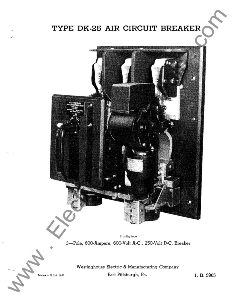
Westinghouse VCP Series User manual

Westinghouse

Westinghouse VCP Series User manual

Westinghouse DK-15 User manual

Westinghouse

Westinghouse DK-15 User manual

Westinghouse DB-50 User manual

Westinghouse

Westinghouse DB-50 User manual
Westinghouse DH User manual

Westinghouse

Westinghouse DH User manual

Popular Circuit Breaker manuals by other brands

Eaton DXC-EXT-2RO Instruction leaflet

Eaton

Eaton DXC-EXT-2RO Instruction leaflet

Siemens 8DA10 Installation and operating instructions

Siemens

Siemens 8DA10 Installation and operating instructions

Siemens SIMATIC PN Installation and operating manual

Siemens

Siemens SIMATIC PN Installation and operating manual

Eaton ZP-IHK installation instructions

Eaton

Eaton ZP-IHK installation instructions

ABB Emax 2 Retrofill Installation and maintenance guide

ABB

ABB Emax 2 Retrofill Installation and maintenance guide

L&T Electrical & Automation OMEGA manual

L&T Electrical & Automation

L&T Electrical & Automation OMEGA manual

Alstom SF6 instruction manual

Alstom

Alstom SF6 instruction manual

WEG SSW900-CRS485-W user guide

WEG

WEG SSW900-CRS485-W user guide

Eaton IZM-KLP-SO-RONIS manual

Eaton

Eaton IZM-KLP-SO-RONIS manual

Eaton AFDD+ Instruction leaflet

Eaton

Eaton AFDD+ Instruction leaflet

GE FD 63 Installation instruction

GE

GE FD 63 Installation instruction

GE AKR-75 Series INSTRUCTIONS - INSTALLATION AND OPERATION

GE

GE AKR-75 Series INSTRUCTIONS - INSTALLATION AND OPERATION

ABB ADVAC Installation & maintenance instructions

ABB

ABB ADVAC Installation & maintenance instructions

Leviton LBHPL installation instructions

Leviton

Leviton LBHPL installation instructions

Siemens 5WG1140-1AB13 quick start guide

Siemens

Siemens 5WG1140-1AB13 quick start guide

Circutor RECmax-CVM series instruction manual

Circutor

Circutor RECmax-CVM series instruction manual

Block PM-0748-200-0 manual

Block

Block PM-0748-200-0 manual

Fonrich FR-DCBS-AFS8B user manual

Fonrich

Fonrich FR-DCBS-AFS8B user manual

manuals.online logo
manuals.online logoBrands
  • About & Mission
  • Contact us
  • Privacy Policy
  • Terms and Conditions

Copyright 2025 Manuals.Online. All Rights Reserved.