schmersal SRB NA-R-C.15 User manual

SRB NA-R-C.15
Operating instructions
Safety-monitoring module
EN 1
1. About this document
1.1 Function
This operating instructions manual provides all the information you
need for the mounting, set-up and commissioning to ensure the safe
operation and disassembly of the safety switchgear. The operating
instructions must be available in a legible condition and a complete
version in the vicinity of the device.
1.2 Target group: authorised qualified personnel
All operations described in this operating instructions manual must
be carried out by trained specialist personnel, authorised by the plant
operator only.
Please make sure that you have read and understood these operating
instructions and that you know all applicable legislations regarding
occupational safety and accident prevention prior to installation and
putting the component into operation.
The machine builder must carefully select the harmonised standards
to be complied with as well as other technical specifications for the
selection, mounting and integration of the components.
1.3 Explanation of the symbols used
Information, hint, note:
This symbol is used for identifying useful additional information.
Caution: Failure to comply with this warning notice could
lead to failures or malfunctions.
Warning: Failure to comply with this warning notice could
lead to physical injury and/or damage to the machine.
1.4 Appropriate use
The products described in these operating instructions are developed to
execute safety-related functions as part of an entire plant or machine. It
is the responsibility of the manufacturer of a machine or plant to ensure
the correct functionality of the entire machinery or plant.
The safety switchgear must be exclusively used in accordance with the
versions listed below or for the applications authorised by the manufac-
turer. Detailed information regarding the range of applications can be
found in the chapter "Product description".
To avoid EMC disturbances, the physical ambient and opera-
tional conditions at the place where the product is installed,
must meet the provisions laid down in the paragraph
"Electromagnetic Compatibility (EMC)" of DIN EN 60204-1.
1.5 General safety instructions
The user must observe the safety instructions in this operating instruc-
tions manual, the country-specific installation standards as well as all
prevailing safety regulations and accident prevention rules.
Further technical information can be found in the Schmersal
catalogues or in the online catalogue on the Internet:
www.schmersal.net.
Content
1 About this document
1.1 Function ..............................................1
1.2 Target group: authorised qualied personnel..................1
1.3 Explanation of the symbols used ...........................1
1.4 Appropriate use ........................................1
1.5 General safety instructions ...............................1
1.6 Warning about misuse ...................................2
1.7 Exclusion of liability .....................................2
2 Product description
2.1 Ordering code .........................................2
2.2 Special versions........................................2
2.3 Destination and use .....................................2
2.4 Technical data .........................................2
2.5 Safety classication .....................................3
3 Mounting
3.1 General mounting instructions .............................3
3.2 Dimensions ...........................................3
4 Electrical connection
4.1 General information for electrical connection..................3
5 Operating principle and settings
5.1 LED functions..........................................3
5.2 Description of the terminals ...............................3
5.3 Notes ................................................3
6 Set-up and maintenance
6.1 Functional testing.......................................4
6.2 Maintenance ..........................................4
7 Disassembly and disposal
7.1 Disassembly...........................................4
7.2 Disposal ..............................................4
8 Appendix
8.1 Wiring examples .......................................4
8.2 Start conguration ......................................4
8.3 Sensor conguration ....................................5
8.4 Actuator conguration ...................................5
9 Declaration of conformity
9.1 EC Declaration of conformity ..............................6
x.000 / August 2014 / v.A. - 101210856-EN / C / 2014-08-14 / AE-Nr. 3071
EN Operating instructions. . . . . . . . . . . . .pages 1 to 6
Translation of the original operating instructions

2
Operating instructions
Safety-monitoring module SRB NA-R-C.15
EN
The information contained in this operating instructions manual is pro-
vided without liability and is subject to technical modifications.
The entire concept of the control system, in which the
safety component is integrated, must be validated to
EN ISO 13849-2.
There are no residual risks, provided that the safety instructions as well
as the instructions regarding mounting, commissioning, operation and
maintenance are observed.
1.6 Warning about misuse
In case of improper use or manipulation of the safety
switchgear, personal hazards or damages to machinery
or plant components cannot be excluded. The relevant
requirements of the standards EN 1088 and EN ISO 13850
must be observed.
1.7 Exclusion of liability
We shall accept no liability for damages and malfunctions resulting from
defective mounting or failure to comply with this operating instructions
manual. The manufacturer shall accept no liability for damages result-
ing from the use of unauthorised spare parts or accessories.
For safety reasons, invasive work on the device as well as arbitrary re-
pairs, conversions and modifications to the device are strictly forbidden;
the manufacturer shall accept no liability for damages resulting from
such invasive work, arbitrary repairs, conversions and/or modifications
to the device.
The safety-monitoring module must only be used when the enclosure is
closed, i.e. with the front cover fitted.
2. Product description
2.1 Ordering code
This operating instructions manual applies to the following types:
SRB NA-R-C.15 24VDC
Only if the information described in this operating instructions
manual are realised correctly, the safety function and therefore
the compliance with the Machinery Directive is maintained.
2.2 Special versions
For special versions, which are not listed in the order code below 2.1,
these specifications apply accordingly, provided that they correspond to
the standard version.
2.3 Destination and use
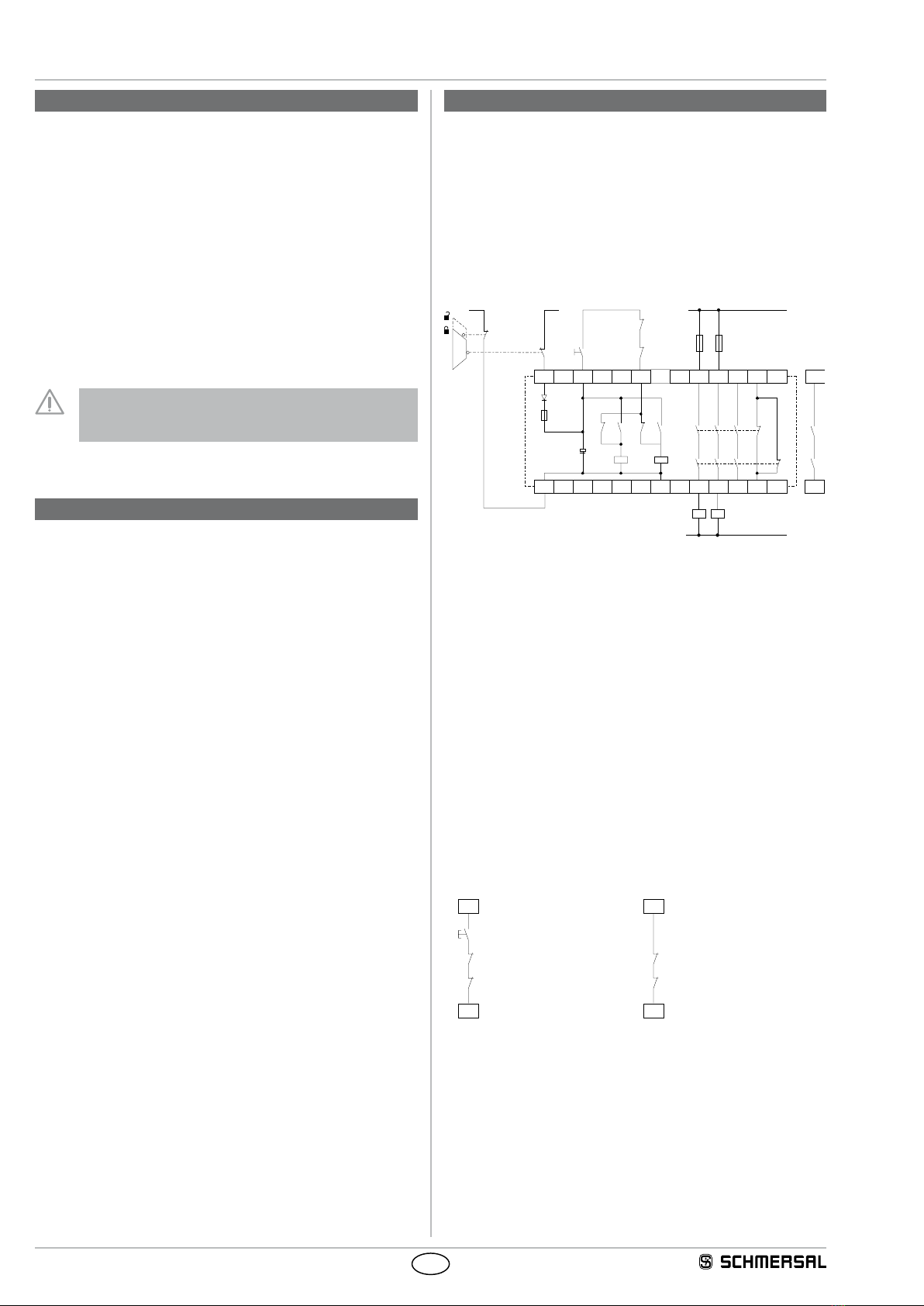
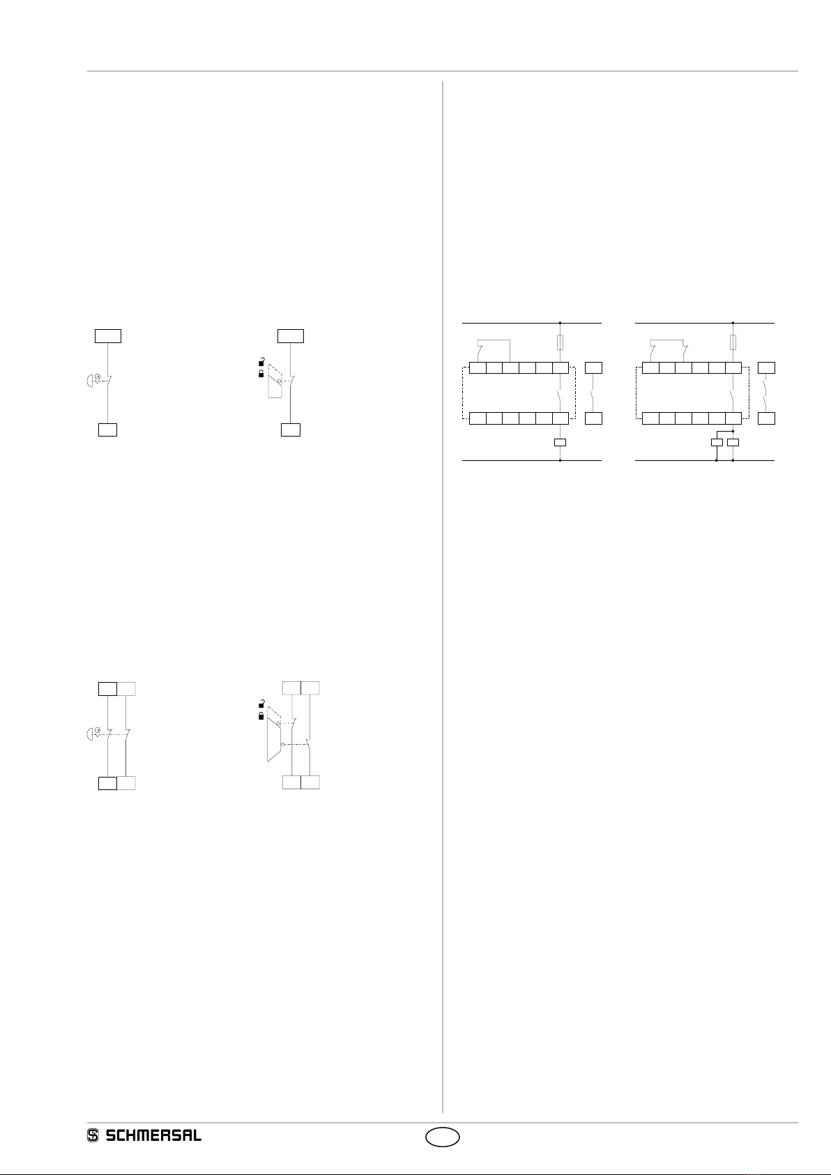
The safety-monitoring modules for integration in safety circuits are
designed for fitting in control cabinets. They are used for the safe
evaluation of the signals of positive break position switches for safety
functions on sliding, hinged and removable safety guards as well as
emergency stop control devices.
The safety function is defined as the opening of the enabling circuits
13-14, 23-24 and 33-34 when the supply voltage C is disconnected.
The safety-relevant current paths with output contacts 13-14, 23-24 and
33-34 meet the following requirements under observation of a B10d value
assessment (also refer to “Requirements of DIN EN ISO 13849-1“):
– Control category 4 - PL e to DIN EN ISO 13849-1
– SIL 3 to DIN EN 61508-2
– SILCL 3 to DIN EN 62061 (meets the requirements
of control category 4 to DIN EN 954-1)
To determine the Performance Level (PL) of the entire safety function
(e.g. sensor, logic, actuator) to DIN EN ISO 13849-1, an analysis of all
relevant components is required.
2.4 Technical data
General data:
Standards: IEC/EN 60204-1, EN 60947-5-1;
EN ISO 13849-1, IEC/EN 61508
Climate resistance: EN 60068-2-78
Mounting: Snaps onto standard
DIN rail to EN 60715
Terminal designations: EN 60947-1
Material of the housings: Thermoplastic
Material of the contacts: AgSnO, self-cleaning,
positive drive
Weight: 190 g
Start conditions: Automatic or start button
Feedback circuit (Y/N): yes
Drop-out delay in case of emergency stop: typ. 30 ms
Pull-in delay: typ. 10 ms
Mechanical data:
Connection type: Screw connection
Cable section: min. 0,25 mm² / max. 2,5 mm²
Connecting cable: rigid or flexible
Tightening torque for the terminals: 0.6 Nm
With removable terminals (Y/N): Nein
Mechanical life: 10 million operations
Electrical life: Derating curve
available on request
Resistance to shock: 10 g / 11 ms
Resistance to vibrations to EN 60068-2-6: 10 ... 55 Hz,
amplitude 0.35 mm
Ambient conditions:
Ambient temperature: –25 °C … +45 °C
Storage and transport temperature: –40 °C … +85 °C
Protection class: Enclosure: IP40
Terminals: IP20
Clearance: IP54
Air clearances and creepage
distances to IEC/EN 60664-1: 4 kV/2 (basic insulation)
EMC rating: to EMC Directive
Electrical data:
Contact resistance in new state: max. 100 mΩ
Power consumption: max. 2.5 VA
Rated operating voltage Ue:24 VDC –15% / +20%,
residual ripple max. 10%
Max. fuse rating of the operating voltage: T 1.0 A
Monitored inputs:
Short-circuit recognition (Y/N): No
Wire breakage detection (Y/N): Yes
Earth leakage detection (Y/N): Yes
Number of NO contacts: 0
Number of NC contacts: 1
Cable length: - 1,500 m mit 1.5 mm²
- 2,500 m mit 2.5 mm²
1-channel
Conduction resistance: max. 40 Ω

3
SRB NA-R-C.15
Operating instructions
Safety-monitoring module
EN
Outputs:
Number of safety contacts: 3
Number of auxiliary contacts: 1
Number of signalling outputs: 0
Switching capacity of the safety contacts: 13-14; 23-24; 33-34:
max. 250 VAC / 6 A ohmic (inductive in
case of appropriate protective wiring)
Switching capacity of the auxiliary contacts: 41-42: 24 VDC / 2 A
Fuse rating of the safety contacts: external (Ik= 1000 A)
to EN 60947-5-1
Safety fuse 8 A quick blow,
6.3 A slow blow
Fuse rating for the auxiliary contacts: external (Ik= 1000 A)
to EN 60947-5-1
Safety fuse 2.5 A quick blow,
2 A slow blow
Utilisation category to EN 60947-5-1: AC-15: 230 VAC / 6 A
DC-13: 24 VDC / 6 A
Dimensions H × W × D: 82 mm × 22.5 mm × 98.8 mm
The data specified in this manual are applicable when the
component is operated with rated operating voltage Ue±0%.
2.5 Safety classification
Standards: EN ISO 13849-1, IEC 61508, EN 60947-5-1
PL: up to e
Control category: up to 4
DC: 99% (high)
CCF: > 65 points
PFH value: ≤ 2.00 × 10⁻⁸/h
SIL: up to 3
Service life: 20 years
The PFH value of 2.00 × 10⁻⁸/h applies to the combinations of contact
load (current through enabling contacts) and number of switching
cycles (nop/y) mentioned in the table below. At 365 operating days per
year and a 24-hours operation, this results in the below-mentioned
switching cycle times (tcycle) for the relay contacts.
Diverging applications upon request.
Contact load nop/y tcycle
20 % 525,600 1.0 min
40 % 210,240 2.5 min
60 % 75,087 7.0 min
80 % 30,918 17.0 min
100 % 12,223 43.0 min
3. Mounting
3.1 General mounting instructions
Mounting: snaps onto standard DIN rails to EN 60715.
Snap the bottom of the enclosure slightly tilted forwards in the DIN rail
and push up until it latches in position.
3.2 Dimensions
All measurements in mm.
Device dimensions (H/W/D): 82 x 22.5 x 98.8 mm
4. Electrical connection
4.1 General information for electrical connection
The electrical connection may only be carried out by authorised
personnel in a de-energised condition.
As far as the electrical safety is concerned, the protection
against unintentional contact of the connected and therefore
electrically interconnected apparatus and the insulation of the
feed cables must be designed for the highest voltage, which
can occur in the device.
Wiring examples: see appendix
5. Operating principle and settings
5.1 LED functions
• K1: Status channel 1
• K2: Status channel 2
• UB: Status operating voltage (LED is on, when the
operating voltage on the terminals A1-A2 is ON)
5.2 Description of the terminals
Voltages: C
D
+24 VDC / 24 VAC
0 VDC / 24 VAC
Outputs: 13-14
23-24
33-34
First safety enabling circuit
Second safety enabling circuit
Third safety enabling circuit
Start: X1-X2
41-42
Feedback circuit and external reset
Auxiliary NC contact
5.3 Notes
Signalling outputs must not be used in safety circuits.
13
SRB NA-
R-C.15
23
K2
UB
K1
33
342414
41
42
X1
X2 D
C
Fig. 1

4
Operating instructions
Safety-monitoring module SRB NA-R-C.15
EN
6. Set-up and maintenance
6.1 Functional testing
The safety function of the safety-monitoring module must be tested.
The following conditions must be previously checked and met:
1. Correct fixing
2. Check the integrity of the cable entry and connections
3. Check the safety-monitoring module's enclosure for damage.
4. Check the electrical function of the connected sensors and
their influence on the safety-monitoring module and the
downstream actuators
6.2 Maintenance
A regular visual inspection and functional test, including the following
steps, is recommended:
1. Check the correct fixing of the safety-monitoring module
2. Check the cable for damages
3. Check electrical function
The device has to be integrated into the periodic check-ups
according to the Ordinance on Industrial Safety and Health,
however at least 1x/year.
Damaged or defective components must be replaced.
7. Disassembly and disposal
7.1 Disassembly
The safety-monitoring module must be disassembled in a de-energised
condition only. Push up the bottom of the enclosure and hang out
slightly tilted forwards.
7.2 Disposal
The safety-monitoring module must be disposed of in an appropriate
manner in accordance with the national prescriptions and legislations.
8. Appendix
8.1 Wiring examples
One-channel control, shown for a guard door monitor with one
positive break contact and external reset button
J
(see Fig. 2)
• Relay outputs: Suitable for 2-channel control, for increase in capacity
or number of contacts by means of contactors or relays with posi-
tive-guided contacts.
• The control system recognises wire-breakage and earth faults in the
monitoring circuit.
•
S
= Feedback circuit
K
A
K
B
L– (A2) L+ (A1)
K1 K2
F1
CX2
KA
KB
D
J
L1
N
K
A
K
B
K1
K2
13 23
14 24
33
34
41
44
X1
UB
Fig. 2
a) Logic
8.2 Start configuration
External reset button (non-monitored start) (see Fig. 3)
• The external reset button is integrated in the feedback circuit in series.
• The safety-monitoring module is activated upon actuation of the reset
button.
Automatic start (Fig. 4)
• The automatic start is programmed by connecting the feedback circuit
to the terminals X1-X2. If the feedback circuit is not required, establish
a bridge.
• Caution: Not admitted without additional measure due to the risk of
gaining access by stepping behind!
• When the SRB NA-R-C.15 safety-monitoring module is used with
the operating mode "Automatic start", an automatic restart after a
shutdown in case of emergency must be prevented by the upstream
control to EN 60204-1 paragraph 9.2.5.4.2 and 10.8.3.
X2
X1
K
A
J
K
B
X2
X1
K
A
K
B
Fig. 3 Fig. 4

5
SRB NA-R-C.15
Operating instructions
Safety-monitoring module
EN
8.3 Sensor configuration
Single-channel emergency stop circuit with command devices to
DIN EN ISO 13850 (EN 418) and EN 60947-5-5 (Fig. 5)
• Wire breakage and earth leakage in the control circuits are detected.
• Possible control categories:
– 1 to EN 954-1
– 2 – PL d to DIN EN ISO 13849-1
Single-channel guard door monitoring circuit with interlocking
devices to EN 1088 (Fig. 6)
• At least one contact with positive break required.
• Wire breakage and earth leakage in the control circuits are detected.
• Possible control categories:
– 1 to EN 954-1
– 2 – PL d to DIN EN ISO 13849-1
C
UB(L+)
C
UB(L+)
Fig. 5 Fig. 6
Dual-channel emergency stop circuit with command devices to
DIN EN ISO 13850 (EN 418) and EN 60947-5-5 (Fig. 7)
• Wire breakage and earth leakage in the control circuits are detected.
• Cross-wire shorts between the control circuits are detected.
• Category 3 – PL d to DIN EN ISO 13849-1 possible.
Dual-channel guard door monitoring circuit with interlocking
device to EN 1088 (Fig. 8)
• At least one contact with positive break required.
• Wire breakage and earth leakage in the control circuits are detected.
• Cross-wire shorts between the control circuits are detected.
• Category 3 – PL d to DIN EN ISO 13849-1 possible.
C
U
B
(L+)
D
U
B
(L–
)
C
U
B
(L+)
D
U
B
(L–
)
Fig. 7 Fig. 8
8.4 Actuator configuration
Single-channel control (see Fig. 9)
• Suitable for increase in capacity or number of contacts by means of
contactors or relays with positive-guided contacts.
• If the feedback circuit
is not required, establish a bridge.
•
S
= Feedback circuit and external reset in series
Dual-channel control with feedback circuit (Fig. 10)
• Suitable for increase in capacity or number of contacts by means of
contactors or relays with positive-guided contacts.
• If the feedback circuit
is not required, establish a bridge.
•
S
= Feedback circuit and external reset in series
X1 X2 13
14
K
A
K
A
K
A
S
L1
N
X1 X2 13
14
K
B
K
A
K
B
K
A
K
B
L1
N
K
A
S
Fig. 9 Fig. 10

6
Operating instructions
Safety-monitoring module SRB NA-R-C.15
EN
SRB NA-R-C.15-C-EN
9. Declaration of conformity
The currently valid declaration of conformity can be
downloaded from the internet at www.schmersal.net.
9.1 EC Declaration of conformity
Name of the safety component: SRB NA-R-C.15
Description of the safety component: Safety-monitoring module for
emergency stop circuits and
guard door monitoring
Relevant EC-Directives: 2006/42/EC EC-Machinery Directive
2004/108/EC EMC-Directive
Person authorized for the compilation
of the technical documentation:
Oliver Wacker
Möddinghofe 30
42279 Wuppertal
Notied body, which approved the full
quality assurance system, referred to
in Appendix X, 2006/42/EC:
TÜV Rheinland Industrie Service GmbH
Alboinstraße 56
12103 Berlin
ID n°: 0035
K. A. Schmersal GmbH & Co. KG
Möddinghofe 30, D - 42279 Wuppertal
Postfach 24 02 63, D - 42232 Wuppertal
Phone: +49 - (0)2 02 - 64 74 - 0
Telefax: +49 - (0)2 02 - 64 74 - 1 00
E-Mail: [email protected]
Internet: http://www.schmersal.com
Place and date of issue: Wuppertal, August 14, 2014
Authorised signature
Philip Schmersal
Managing Director
EC Declaration of conformity
Translation of the original
Declaration of Conformity
K.A. Schmersal GmbH & Co. KG
Möddinghofe 30
42279 Wuppertal
Germany
Internet: www.schmersal.com
We hereby certify that the hereafter described safety components both in its basic design and
construction conform to the applicable European Directives.
Table of contents
Other schmersal Measuring Instrument manuals
Popular Measuring Instrument manuals by other brands

GREER Company
GREER Company MicroGuard 510 Retrofit Calibration

Keysight Technologies
Keysight Technologies C Series user guide

Welch Allyn
Welch Allyn TR-2 instructions

LINSHANG
LINSHANG LS182 user manual

Precision Digital Corporation
Precision Digital Corporation PD6801 instruction manual

Iskra
Iskra PNA 784 quick guide