3
SRB-E-402FWS-TS
Operating instructions
Fail-safe delay timer / Standstill monitor
EN
To determine the Performance Level (PL) to EN ISO 13849-1 of the
entire safety function (e.g. sensor, logic, actuator), an assessment of all
relevant components is required.
The entire concept of the control system, in which the safety
component is integrated, must be validated to the relevant
standards.
2.4 Technical data
General data
Standards: EN 60204-1, EN 60947-5-1, EN ISO 13849-1,
IEC 61508, EN 62061
EMC rating: to EMC Directive
Air clearances and creepage distances: to EN 60664-1
Mounting: standard rail to EN 60715
Terminal designations: EN 60947-1
Electrical characteristics:
Rated operating voltage Ue: 24 VDC –20%/+20%,
residual ripple max. 10%
Frequency range: −
Mains unit/mains power supply: An ES1 or PELV/SELV mains adapter
must be used as a voltage source or be ensured by means
of additional measures so that the output voltage of the
power adapter in the event of an error does not exceed 60 V.
Mains power supply must harmonise with device safety
(characteristic/melting property) so that triggering is ensured.
Power consumption: 3 W (+ load of the safety outputs)
Fuse rating for the operating voltage: We recommend a circuit
breaker type Z (max. 16 A) or a fine
fuse (max. 15 A, delayed action).
UL Rating of external fuse: max. 16 A, only use fuses in
accordance with UL 248 series
Insulation values to EN 60664-1:
Rated insulation voltage Ui:
- Safety contacts: 250 V
- Safety outputs: 50 V
Rated impulse withstand voltage Uimp:
- Safety contacts 13/14, 23/24: 6 kV
- Safety output Q1/Q2: 0.8 kV
Overvoltage category: III
Degree of pollution: 2
Drop-out delay on "supply failure": < 10 ms
Bridging in case of voltage drops: typ. 5 ms
Readiness after switching on voltage: < 1.5 s
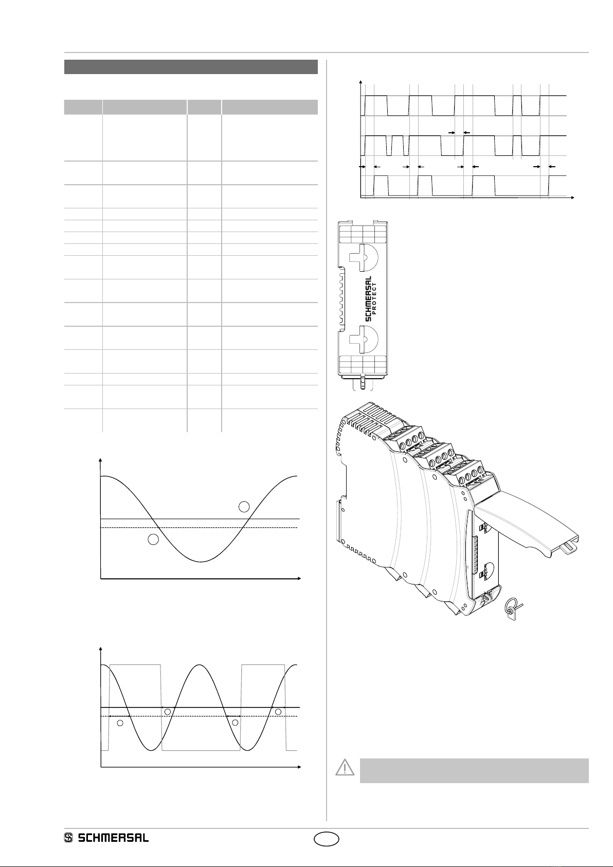
Frequency measurement tolerance: < 2%
Time measurement tolerance: 2% + 30 ms
Control current circuits/inputs:
Inputs S12, S22, S32, S42: 24 VDC / 8 mA
Max. input frequency: 6000 Hz
Inputs X2, X3, X4, X5, X7: 24 VDC / 8 mA
Clock outputs S11, S21, S31, S41: > 20 VDC, 10 mA per output
Cable length: 1500 m with 1.5 mm²
2500 m with 2.5 mm²
Conduction resistance: max. 40 Ω
Relay outputs:
Switching capacity of the safety contacts: 13/14, 23/24:
max. 250 V, 6 A ohmic,
min. 10 VDC / 10 mA
(Derating see 2.5)
Fuse rating of the safety contacts: external (Ik= 1000 A)
to EN 60947-5-1
Safety fuse 10 A quick blow, 6 A slow blow
Utilisation category to EN 60947-5-1: AC-15: 230 V / 4 A
DC-13: 24 V / 4 A
Switching capacity of the auxiliary contacts: 41-42: 24 VDC / 1 A
Fuse rating for the auxiliary contact: safety fuse
2.5 A quick blow, 2 A slow blow
Electrical life: refer to 2.5
Mechanical life: 10 million operations
Semi-conductor outputs:
Switching capacity of the safety outputs: Q1/Q2: max. 2 A
Voltage drop: < 0.5 V
Leakage current: < 1 mA
Max. fuse rating of the safety outputs: refer to "Operating voltage"
Test impulse of the safety outputs: < 1 ms (negative),
< 100 µs (positive)
Utilisation category to EN 60947-5-1: DC-13: 24 V / 2A
Switching capacity of signaling outputs: semi-conductor outputs Y1:
24 VDC/100 mA
Fuse rating of the signalling outputs: internal electronic trip,
tripping current > 100 mA
Electrical life: (Derating refer to 2.5)
Max. switching cycles / minute: 20
Inductive consumers: provision is to be made for suitable
protective wiring for suppression.
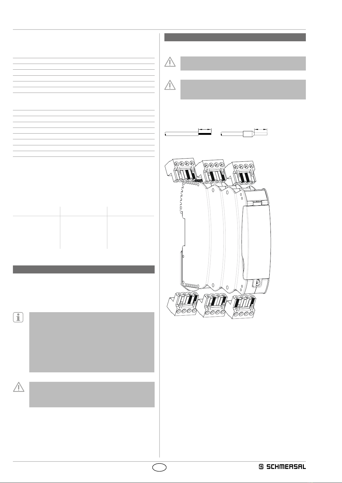
Mechanical data:
Connection type: refer to 2.1
Cable section: refer to 2.1
Connecting cable: rigid or flexible
Tightening torque for the terminals: 0.5 Nm
Material of enclosure: glass-fibre reinforced
thermoplastic, ventilated
Weight: 180 g
Ambient conditions:
Ambient temperature: –25°C … +60°C
(non condensing)
Storage and transport temperature: –40°C … +85°C
(non condensing)
Degree of protection: Enclosure: IP40
Terminals: IP20
Clearance: IP54
Resistance to shock: 30 g / 11 ms
Resistance to vibrations
to EN 60068-2-6: 10 ... 55 Hz, amplitude 0.35 mm
Altitude: max. 2,000 m
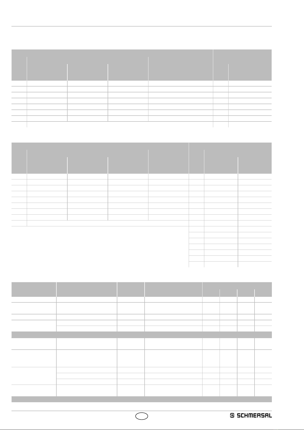
2.5 Derating / electrical lifespan of safety contacts
No derating with individual installation of modules.
Derating on request if several modules are installed one after the
other without spacing and with maximum output load and ambient
temperatures.
Electrical life of the safety contacts
DC13 24V
AC15 230V
AC1 230V
DC1 24V
1.000.000
100.000
10.000
Operations
Contact load in amperes