Schneeberger MINISCALE PLUS User manual

Mounting instructions 2017
MINISCALE PLUS
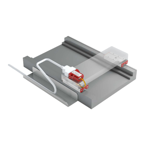
The unique miniature guideway
with integrated measuring system
and a resolution of 0.1 µm
www.servo2go.com
sales@servo2go.com
www.servo2go.com
Toll Free Phone: 877-378-0240
Toll Free Fax: 877-378-0249
www.servo2go.com
Sold & Serviced By:

Disclaimer
This publication has been compiled with great care and all information has been
checked for accuracy. However, we can assume no liability for incorrect or incomplete
information. We reserve the right to make changes to the information and technical
data as a result of enhancements to our products. Reprinting or reproducing, even
in part, is not permitted without our written consent.
www.servo2go.com
sales@servo2go.com
www.servo2go.com
Toll Free Phone: 877-378-0240
Toll Free Fax: 877-378-0249
www.servo2go.com
Sold & Serviced By:

3
1
2
3
4
5
6
7
8
9
10
1
Table of Contents
Contents
Contents 3
Introduction 5
2.1 Scope of Application 5
2.2 Supplementary Literature 5
Safety Instructions 6
3.1. Authorized Staff 6
3.2. Intended Use 6
3.3. General Safety and Protective Measures 6
3.4. Environmental Protection 6
Handling and Storage 7
4.1. Transport 7
4.2. Protection 7
Installation and Adjustment Guidelines for MINIRAIL and MINISCALE PLUS 8
5.1 Serial Number on Guideway and Carriages 8
5.2 Locating and Supporting Surfaces 8
5.3 Methods for Aligning Guideways 9
5.4 Preparing for Installation 10
5.5 Installing the Guideway 11
5.6 Tightening Torques for the Fastening Screws 13
5.7 Lubrication of MINISCALE PLUS 13
5.8 Connecting the Flexible Printed Circuit Board to the Interface Module 14
Output Signals and Supplying MINISCALE PLUS and Interface Module 17
6.1 Supply Voltage and Current Consumption 17
6.2 ANALOG Interface Module (Analog Signal 1Vss) 17
6.3 DIGITAL Interface Module (Digital Signal TTL) 20
6.4 Recommendations for the Customer-Supplied Cable 24
System Accuracy 25
Matching the Interface Module with Carriages and Guideway 26
8.1 Adjustment Procedure for a Replacement DIGITAL Interface Module 26
Technical Principles to Aid Usage of MINISCALE PLUS 27
9.1 Interpolation 27
9.2 Digital Signaling and Evaluation 28
9.3 Analog Signal Frequency 29
9.4 Accuracy Class 29
9.5 Resolution 29
9.6 Sampling Rate 29
9.7 Repeatability 29
9.8 Referencing 30
9.9 Periodic Deviations 30
9.10 Interpolation Errors 30
9.11 Comparator Errors 30
9.12 Single-Ended Signaling 31
9.13 Differential Signaling 31
9.14 Direction of Travel 31
Error Description for MINISCALE PLUS 32
www.servo2go.com
sales@servo2go.com
www.servo2go.com
Toll Free Phone: 877-378-0240
Toll Free Fax: 877-378-0249
www.servo2go.com
Sold & Serviced By:

4
www.servo2go.com
sales@servo2go.com
www.servo2go.com
Toll Free Phone: 877-378-0240
Toll Free Fax: 877-378-0249
www.servo2go.com
Sold & Serviced By:

5
2
2.1 / 2.2 Introduction
Introduction
2.1. Scope of Application
These instructions describe installation of the MINIRAIL and MINISCALE PLUS
miniature profiled linear guideway systems.
2.2. Supplementary Literature
MINI-X Product Catalog
Configuration of MINISCALE PLUS with MINIRAIL
www.servo2go.com
sales@servo2go.com
www.servo2go.com
Toll Free Phone: 877-378-0240
Toll Free Fax: 877-378-0249
www.servo2go.com
Sold & Serviced By:

6
3
3.1. Authorized Staff
MINIRAIL and MINISCALE PLUS must only be assembled by appropriately trained
specialists who have read and understood these instructions.
3.2. Intended Use
MINIRAIL and MINISCALE PLUS can only be exposed to the approved environ-
mental influences (see MINI-X product catalogue, MINIRAIL and MINISCALE PLUS
technical information)
3.3. General Safety and Protective Measures
• The power supply should be disconnected prior to any work on electrical
equipment.
• ESD regulations should be observed when handling ESD-vulnerable parts (EN
100015-1).
• Country-specific regulations, standards and guidelines for accident prevention
must be observed.
3.4. Environmental Protection
• Lubricants should be disposed of in an environmentally responsible way.
• Decommissioned components should be disposed of in accordance with local/
national laws and guidelines.
Safety Instructions
www.servo2go.com
sales@servo2go.com
www.servo2go.com
Toll Free Phone: 877-378-0240
Toll Free Fax: 877-378-0249
www.servo2go.com
Sold & Serviced By:

7
4
4.1. Transport
MINISCALE PLUS and MINIRAIL are high-precision components and should be
handled with care. For transportation of these products in-house, the following
points should therefore be noted:
• Transport guideways and accessories in their original packaging
• Protect guideways against impacts
• Always transport MINIRAIL and MINISCALE PLUS carriages on guide rails or on
the protective plastic rail
4.2. Protection
The following instructions should be noted to protect against damage:
• Storage in the original packaging is only possible for a limited period. The
condition of the products should be checked at regular intervals.
• Protect products against moisture/humidity and do not store them out in the
open
(10% - 70%, non-condensing).
• Ensure the correct temperature range:
MINIRAIL -40° C to +80° C.
MINISCALE PLUS -40° C to +80° C.
• Only remove the products from their original packaging at their installation
location and immediately prior to assembly.
• Check the state of lubrication.
• Always store MINIRAIL and MINISCALE PLUS carriages on the guide rail or
protective plastic rail so that the rolling elements are protected.
• MINISCALE PLUS is sensitive to electrostatic discharge! The electronics can be
damaged if precautions are not taken against ESD; ESD regulations should
therefore be observed when handling ESD-vulnerable parts (EN 100015-1).
• The power supply should be switched off prior to connecting or disconnecting
cables, and precautions should be taken to ensure it cannot be switched on
again unintentionally.
Improper handling of the guideways can lead to preliminary damage and thus to
premature failure.
Handling and Storage
3.1 / 3.2 / 3.3 / 3.4 / 4.1 / 4.2 Handling and Storage
www.servo2go.com
sales@servo2go.com
www.servo2go.com
Toll Free Phone: 877-378-0240
Toll Free Fax: 877-378-0249
www.servo2go.com
Sold & Serviced By:

8
5Installation and Adjustment Guidelines
5.1. Serial Number on Guideway and Carriages
Both guideways and carriages are labelled with serial numbers. The serial number
on guideways and carriages is located next to the SCHNEEBERGER logo.
5.2. Locating and Supporting Surfaces
Locating and supporting surfaces on carriages and guideways are designated as
follows.
Standard sizes 7, 9, 12 and 15 Wide sizes 14, 18, 24 and 42
Carriage locating and supporting surfaces
Guideway locating and supporting surfaces
The polished locating side of the carriage is opposite the carriage side with the
company logo / type designation.
The guideway can be located on both sides.
Logo side Logo side
www.servo2go.com
sales@servo2go.com
www.servo2go.com
Toll Free Phone: 877-378-0240
Toll Free Fax: 877-378-0249
www.servo2go.com
Sold & Serviced By:

9
5Installation and Adjustment Guidelines
5.1 / 5.2 / 5.3 Installation and Adjustment Guidelines
5.3. Methods for Aligning Guideways
Alignment of the guide rails depends on the level of accuracy needed and must be
specified in the construction phase of the machine, since this is when the number
of locating surfaces as well as their positions is determined. A distinction is made
between the following types of alignment:
No reference edge available
• Alignment by hand without tools
• Not recommended
• Very low level of accuracy
No reference edge available
• Alignment by hand with tools, e. g. aligning gauge, guide strip, dial gauge,
installation carriage
• Medium to high level of accuracy depending on the complexity
Lateral reference
• Alignment by means of pressing against the locating surface
• High level of accuracy, depending on the accuracy of the reference edge
• Very quick due to predefined reference edge
Lateral locating surface and additional lateral clamping
• Alignment by pressing against the locating surface with the help of lateral
clamping elements
• Very high level of accuracy, depending on the accuracy of the reference edge
• Very quick due to predefined reference edge
www.servo2go.com
sales@servo2go.com
www.servo2go.com
Toll Free Phone: 877-378-0240
Toll Free Fax: 877-378-0249
www.servo2go.com
Sold & Serviced By:

10
5
A
B
Installation and Adjustment Guidelines
5.4. Preparing for Installation
5.4.1 Required tools and equipment
• Oil stone
• Lubricant
• Torque wrench
• Fastening screws
• White spirit or rubbing alcohol
5.4.2 Preparing the locating surfaces
• Check locating surfaces of the machine bed and mounting plate for shape and
position accuracy.
• Clean all locating surfaces thoroughly. Remove ridges and surface irregularities
with an oil stone.
• Use white spirit or rubbing alcohol to clean the locating and supporting surfaces
of guideways. Do not use paint thinner!
• Clean dirty guideways with a soft, lint-free cloth. Do not use compressed air!
• Lightly oil the locating surfaces on the guideways and carriages.
Locating surfaces
A Reference on the mounting plate for the carriage
B Reference on the machine bed for the guideway (both sides of the guideway can be used as locating surfaces)
www.servo2go.com
sales@servo2go.com
www.servo2go.com
Toll Free Phone: 877-378-0240
Toll Free Fax: 877-378-0249
www.servo2go.com
Sold & Serviced By:

11
5Installation and Adjustment Guidelines
5.4 / 5.5 Installation and Adjustment Guidelines
5.5 Installing the Guideway
• Before installation, the guideway, machine bed, mounting plate and fastening
screws must all be at room temperature.
• The MINISCALE PLUS sensor is an electrostatically vulnerable component and
is delivered in ESD-protective packaging. To ensure the sensor remains
protected, the ESD-protective packaging should not be removed during
installation of the MINISCALE PLUS guideway.
• Always tighten the fastening screws with a torque wrench. See chapter 5.6 for
tightening torques.
• Always brace the locating surface of the guideway against the locating surface
of the machine bed. The guideway can be located on both sides, the locating
side of the carriage is opposite the carriage side with the company logo / type
designation.
• Alternate between sides of the guideway, starting at the middle, when
tightening fastening screws.
Fixing MINIRAIL Guideways Correctly
www.servo2go.com
sales@servo2go.com
www.servo2go.com
Toll Free Phone: 877-378-0240
Toll Free Fax: 877-378-0249
www.servo2go.com
Sold & Serviced By:

12
5Installation and Adjustment Guidelines
5.5.1 Cleaning Dimensional Scales
The dimensional scale of the measuring system is located on the top side of the
MINISCALE PLUS guideway. After the guideway has been fixed but before the
carriage is mounted, the dimensional scale must be cleaned to ensure it can be
read by the sensor. Lubricants, fingerprints and other dirt residue must be
removed.
A clean, lint-free cloth should be used for cleaning. White spirit or rubbing alcohol
are suitable cleaning fluids.
Wipe down the dimensional scale on the surface of the guideway with a soaked
cloth. Repeat the cleaning several times with a clean cloth for heavy dirt.
5.5.2 Mounting and dismounting carriages (MINIRAIL or MINISCALE PLUS)
onto guideways
Use the included protective plastic rail. This protects the carriage from dirt and
prevents it jamming, causing the ball bearings to subsequently escape.
Place the protective plastic rail in line with the guide rail and slide the MINIRAIL or
MINISCALE PLUS carriage onto it.
For MINISCALE PLUS carriages, ensure the sensor is over the dimensional scale
on the guideway.
www.servo2go.com
sales@servo2go.com
www.servo2go.com
Toll Free Phone: 877-378-0240
Toll Free Fax: 877-378-0249
www.servo2go.com
Sold & Serviced By:

13
5
5.5 / 5.6 / 5.7 Installation and Adjustment Guidelines
Installation and Adjustment Guidelines
5.6. Tightening Torques for the Fastening Screws
The recommended torque values can be found in the table. These values apply to
oiled screws.
The friction coefficient μ can be reduced by up to half when using greases
containing MoS2. The corresponding torque values should be reduced by half.
The following table shows the torque values for the fastening screws of strength
class 12.9 (friction coefficient 0.125) and of the strength class A2-70 (friction
coefficient 0.2) in accordance with DIN 912:
Thread size Tightening torque in Ncm
Strength class 12.9 Strength class A2-70
M1.6 28 20
M2 60 30
M3 210 110
M4 500 260
5.7. Lubrication of MINISCALE PLUS
If MINISCALE PLUS or MINIRAIL carriages are used on a guideway, all carriages
are lubricated during manufacture (with KLÜBER Isoflex NBU15). Regarding
subsequent lubrication, refer to the guidelines for MINISCALE PLUS.
5.7.1 Subsequent Lubrication Intervals for MINISCALE PLUS
The subsequent lubrication interval depends on many variables, e.g. load, working
environment, speed, etc. and therefore cannot be calculated. The lubrication point
must therefore be observed over a longer period of time.
For subsequent lubrication, use only grease (Klüber Isoflex NBU15).
A film of grease should be applied to the tracks of the guideway using a lint-free
cloth. The carriages should then be moved along the entire length of the rail so that
the lubricant is applied to the ball bearings and distributed along the guideway. The
grease should be applied sparingly in order to ensure no lubricant gets into the
measuring system optics.
The surface of the guideway must then be cleaned, and the dimensional scale
wiped over with white spirit or rubbing alcohol so that it can be read by the sensor.
www.servo2go.com
sales@servo2go.com
www.servo2go.com
Toll Free Phone: 877-378-0240
Toll Free Fax: 877-378-0249
www.servo2go.com
Sold & Serviced By:
14
5
J
K
L
E
D
C
BAG
F
C
D
C
H
F
Installation and Adjustment Guidelines
5.8. Connecting the Flexible Printed Circuit Board to the Interface Module
MINISCALE PLUS is an optical, incremental measuring system. It consists of the
MINIRAIL guide system and the following additional standard components:
• Dimensional scale on the guide rail
• Optical sensor on the carriage with flexible printed circuit board
• Interface module with D-sub 9 connector (the control cable with D-sub 9
connector must be supplied by the customer and be a flexible cable where
necessary).
5.8.1 Overview of Relevant Components
A Carriages
B Optical sensor
C Flexible printed circuit board (must not be exposed to dynamic loads)
D Guideway
E Dimensional scale on the guideway
F Interface module with D-sub 9 connector
G Control cable (supplied by customer)
H ZIF connector
5.8.2 ESD Protection
The MINISCALE PLUS optical sensor is an electrostatically vulnerable component
and is delivered in ESD-protective packaging. (Electrostatic Discharge).
J ESD sticker
K ESD-protective packaging
L Conductive tape
As soon as it is removed from the protective packaging, MINISCALE PLUS and the
interface module of the flexible printed circuit board must be protected against
electrostatic fields and discharge. As soon as MINISCALE PLUS is assembled and
connected ready for use, it is protected from ESD.
www.servo2go.com
sales@servo2go.com
www.servo2go.com
Toll Free Phone: 877-378-0240
Toll Free Fax: 877-378-0249
www.servo2go.com
Sold & Serviced By:

15
5
L
C
Installation and Adjustment Guidelines
5.8.3 Connecting to the Interface Module
These installation instructions are not a guide on ESD but are simply to give an
overview of how MINISCALE PLUS should be operated.
An ESD wrist strap with ground cable or crocodile clamps on the machine bed
acting as such should be used as a minimum when installing MINISCALE PLUS.
Provided the MINISCALE PLUS flexible printed circuit board is in the ESD-protec-
tive packaging, no ESD protection or wrist strap is necessary.
The ESD-protective packaging should not be removed during installation of the
guideway so that the sensor remains protected.
The ESD-protective packaging can only be removed once MINISCALE PLUS is
grounded on the machine bed and the person is properly protected from ESD
(e.g. by wearing an grounded wrist strap).
Remove tape (L)
The flexible printed circuit board (C) must not be damaged during removal of the
protective packaging.
After the protective packaging has been removed, MINISCALE PLUS is unprotect-
ed and must only be touched by ESD-protected persons.
5.8 Installation and Adjustment Guidelines
www.servo2go.com
sales@servo2go.com
www.servo2go.com
Toll Free Phone: 877-378-0240
Toll Free Fax: 877-378-0249
www.servo2go.com
Sold & Serviced By:

16
5
Installation and Adjustment Guidelines
Open ZIF connector (H)
Insert the flexible printed circuit board (C) into the ZIF connector (H)
of the interface module (F) without touching the gold contact points
on the printed circuit board.
Make sure that the contact surfaces of the flexible
printed circuit board are facing upwards so that
contact is ensured.
Once the flexible printed circuit board has been inserted, push the
ZIF connector towards it.
Once the sensor is connected to the interface module, which is
connected to the grounded machine, it is protected from ESD and
can be touched without ESD protection.
The flexible printed circuit board between the sensor and the
interface module can only be used statically. The bending radius of
the flexible printed circuit board must not fall below 2 mm.
www.servo2go.com
sales@servo2go.com
www.servo2go.com
Toll Free Phone: 877-378-0240
Toll Free Fax: 877-378-0249
www.servo2go.com
Sold & Serviced By:

17
6
Ua1+
Ua0+
Ua2+
Ua2-
Ua0-
Ua1-
2.3V
100μm
+
-
+
-
+
-
0.5V
≈100 μm
Output Signals and Supply
5.8 / 6.1 Output Signals and Supply
The sensor head in the carriage sends sinusoidal output signals when the carriage
is moved relative to the dimensional scale along the guide rail.
These signals are interpreted in the interface module and displayed in analog
(see chapter 6.2) or digital form (see chapter 6.3), depending on the type of
interface module.
6.1 Supply Voltage and Current Consumption
Supply voltage: 5 V DC +/- 5%
This must be adhered to in order to generate output signals.
Current consumption: 60 mA (analog) / 70 mA (digital)
6.2 ANALOG Interface Module (Analog Signal 1Vss)
6.2.1 Output Format:
Differential, sin/cos analog signals with reference pulse
1 Vss (at 100Ω)
The incremental sine and cosine signals are displaced 90° and correlate with the
markings on the incremental track. One electrical signal period (360°) corresponds
exactly to the scale increment on the dimensional scale, which amounts to 100 μm.
The reference pulse always marks electrically a particular section of the path of the
sine and cosine signals. The point of intersection of the two signals within the
reference pulse marks a precisely defined position on the dimensional scale.
The sine signal either lags behind the cosine signal or occurs before it, depending
on the direction of movement.
The analog signal must be interpolated by the customer in order to achieve an
appropriate resolution (e.g. Period 100 µm, interpolation 250 times, analysed 4 times
results in a resolution of 0.1 µm. The frequency of the electronics must be adjusted
to the travelling speed. E.g. A speed of 2 m/s with signal period before interpolation
of 100 µm results in a frequency of 20 kHz (see calculation in chapter 9.3)
Single-ended signals
Analog interface
module output
Differential signals
Reference point
Sine
Cosine
Reference
www.servo2go.com
sales@servo2go.com
www.servo2go.com
Toll Free Phone: 877-378-0240
Toll Free Fax: 877-378-0249
www.servo2go.com
Sold & Serviced By:

18
6
6.2.2 Signaling
In order to increase the resistance to interference, transmitting the signals in an
interpolated form is recommended. Transmitting signals in opposite phases
symmetrically can almost entirely prevent interference. The amplitude of the
differentially transmitted signals equates to 1VSS.
For single-ended signaling, the voltage changes relative to a reference potential.
The amplitude of such a signal amounts to 0.5 V.
This interface works with all standard controllers that support a 1 VSS voltage
interface.
6.2.3 Pin allocation for analog interface module 1VSS (IM SCPA)
Interface module: Male 9-pin D-sub connector.
Customer-supplied cable: Female 9-pin D-sub connector
Pin Signal Signal type
1 Ua1 - Sine-
2 GND Supply voltage
3 Ua2 - Cosine-
4 ERR NOT Error signal
5 Ua0 - Reference signal -
6 Ua1 + Sine +
7 +5V DC Supply voltage
8 Ua2 + Cosine +
9 Ua0 + Reference signal +
6.2.4 Function Check
The green LED will light up if the MINISCALE PLUS is correctly supplied with
power.
Output Signals and Supply
Interface module without MINISCALE PLUS flexible
printed circuit board. Both the green and red LEDs
light up
Interface module with correctly connected
MINISCALE PLUS flexible printed circuit board.
The green LED lights up
www.servo2go.com
sales@servo2go.com
www.servo2go.com
Toll Free Phone: 877-378-0240
Toll Free Fax: 877-378-0249
www.servo2go.com
Sold & Serviced By:

19
6
6.2 Output Signals and Supply
Output Signals and Supply
If the carriage is on the guideway and the LED lights up red despite the flexible
printed circuit board being inserted, the error should be found using the table in
chapter 10 ‚Error Description’.
LED Supply missing Supply connected, normal operation Error condition
red Red LED does not light up Red LED does not light up Red LED lights up red
green Green LED does not light up Green LED lights up green Green LED lights up green
The status of the interface module is shown electronically with the output («ERR
NOT»). ERR NOT is a 5-volt output (TTL level), where a «low - signal» = «pending
error» and a «high - signal» = «no error».
6.2.5. Using the analog interface module with the USB counter 026 or 046
(for technical information, see chapter 12 in the MINI-X product
catalogue).
The USB counters mentioned above allow MINISCALE PLUS to be connected
directly to a computer via USB.
Current consumption:
< 150 mA
Storage temperature of the USB counter:
-30 °C to + 70 °C
Operating temperature of the USB counter:
0° to 45 °C in relative humidity of <75%.
When using the USB counter’s analog input, the interpolator built into the USB
counter reaches a resolution of just 256 (= 28). As a result, the resolution displaya-
ble with the USB counter is limited to 0.39 µm. A speed of 5 m/s is guaranteed,
and the maximum input frequency amounts to 75 kHz (based on one channel, e.g.
the A signal.)
The maximum length for the USB cable is 5 meters. With a USB repeater cable,
the USB connection can be extended up to a maximum of 25 m.
• For operating the USB counter, PC software for demonstrating the functionality
is available.
• A DLL file is available for customers that wish to write their own software
applications.
1-axis USB Counter 026
3-axis USB Counter 046
PC software for USB counter 026
www.servo2go.com
sales@servo2go.com
www.servo2go.com
Toll Free Phone: 877-378-0240
Toll Free Fax: 877-378-0249
www.servo2go.com
Sold & Serviced By:

20
6
A+
A-
B+
B-
R-
R+
≈4.1V
≈0.2V
R
A
B
100nm
100nm
+
-
+
-
+
-
100nm
Output Signals and Supply
6.2.6 Using the analog interface module with the 2-axis SIRIUS II position
indicator (for technical information, see chapter 12 in the MINI-X
product catalogue).
Storage temperature of the position indicator:
-40 °C to + 70 °C
Operating temperature of the position indicator:
0 °C to 45 °C in relative humidity between 15% and 95% without condensation.
The maximum input frequency is 100 kHz which guarantees a speed of 5 m/s. The
built-in interpolation factor for an analog input of the position indicator is 20. This
achieves a resolution of just 5 µm. We therefore recommend using the SIRIUS II
position indicator with the digital input option, along with the MINISCALE PLUS
digital interface module.
6.3 DIGITAL Interface Module (Digital Signal TTL)
6.3.1 Output Format:
Differentially interpolated digital signals with reference pulse (A, B, R)
TTL signal, 5 volt level (RS422)
The digital interface module both processes the raw signals and interpolates the
processed analog signals. The interpolation achieves a resolution of 100 nm.
The digital signal waveform consists of an A and a B signal. The spacing between
the two edges of signals A and B corresponds exactly to a distance of 100 nm.
Accordingly, the scale increment of 100 μm on the incremental track of the
dimensional scale is divided into 1000 sections of 100 nm by means of interpola-
tion.
The A signal either lags behind the B signal or occurs before it, depending on the
direction of movement.
The reference pulse is as wide as the spacing between the two signal edges of
signals A and B, which is 100 nm. The edges of the incremental and reference
signals are synchronised.
2-axis SIRIUS II position indicator
Single-ended signals
Digital interface
module output
Differential signals
www.servo2go.com
sales@servo2go.com
www.servo2go.com
Toll Free Phone: 877-378-0240
Toll Free Fax: 877-378-0249
www.servo2go.com
Sold & Serviced By:
This manual suits for next models
1
Table of contents
Other Schneeberger Measuring Instrument manuals
Popular Measuring Instrument manuals by other brands

Stanley
Stanley STHT77366 manual

Gossen MetraWatt
Gossen MetraWatt lunasix Operating instructions manual

opti-sciences
opti-sciences ccm-200 plus Operator's manual

AIDETEK
AIDETEK DM4070 Operation manual

EMH metering
EMH metering NXT4 Instructions for use

Dostmann Electronic
Dostmann Electronic MS 85 Instructions for use

Spirax Sarco
Spirax Sarco ILVA20 Installation

Elotech
Elotech A4000 Description and operating manual

getemed
getemed PhysioMem PM 100 4G Instructions for use

MONARCH INSTRUMENT
MONARCH INSTRUMENT Pocket Laser Tach 200 instruction manual

Konica Minolta
Konica Minolta Vivid VI-910 brochure

Dilon
Dilon Navigator 2.0 User & service manual