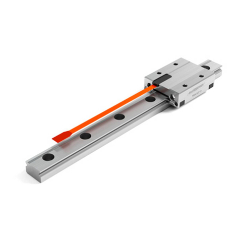
Schneeberger MINISLIDE MSQscale Manual

MINISLIDE MSQscale
Mounting Instructions | Technical Information
Mounting Instructions 2019

Latest version of the catalogs
You can always find the latest version of our catalogs in the Download area of our
website.
Disclaimer
This publication has been compiled with great care and all information has been
checked for accuracy. However, we can assume no liability for incorrect or incomplete
information. We reserve the right to make changes to the information and technical
data as a result of enhancements to our products. Reprinting or reproducing, even
in part, is not permitted without our written consent.
C100493

3
Table of Contents
Page number
Table of Contents
1Safety Instructions 5
1.1 Scope of Application 5
1.2 Authorized Staff 5
1.3 Intended Use 5
1.4 General Safety and Protective Measures 5
1.5 Environmental Protection 5
1.6 Transport 5
2 CongurationoftheBaseStructure 6
2.1 General 6
2.2 Surface Quality 6
2.3 Flatness of the Mounting Surfaces 6
2.4 Locating Height and Corner Radii 7
2.5 Installation Methods 7
3 InstallationandAdjustmentGuidelinesfortheGuideway 9
3.1 Preparing for Installation 9
3.2 Installing the Guideway 10
3.3 Cleaning the Dimensional Scale 11
3.4 Lubrication 11
4 InstallationGuidelinesfortheMeasuringSystem 12
4.1 ESD Protection 12
4.2 Mating the Interface Module and the Guideway 13
4.3 Interface Module Installation Options 14
4.4 Connecting the Flexible Sensor Print to the Interface Module 15
4.5 Extension Installation (FFC Cable) 16
4.6 Connecting a Customer-provided Cable 19
5 Commissioning 20
5.1 Signal Transmission 20
5.2 Pin Assignments 21
5.3 Controller 22
5.4 Function Check 23
6 TechnicalPrinciples 24
6.1 System Accuracy 24
6.2 Interpolation 25
6.3 Evaluation of Digital Signals 26
6.4 Signal Frequency 27

4
Table of Contents
Page number
7 TermsandDenitions 28
7.1 Interface Module 28
7.2 Accuracy Class 29
7.3 Repeatability 29
7.4 Referencing 29
7.5 Periodic Deviations 29
7.6 Comparator Errors 30
7.7 Sampling Rate 30
7.8 Single-Ended Signaling 30
7.9 Differential Signaling 30
7.10 Direction of Travel 30
8 ApplicationTips 31
8.1 Operating Conditions for the MINISLIDE MSQscale 31
8.2 EMC Characteristics of the MINISLIDE MSQscale 31
8.3 Magnetic Effects on the MINISLIDE MSQscale 31
9 Troubleshooting 32
9.1 Aligning the Digital Interface Module 32
9.2 Error Description 33

5
Safety Instructions
These instructions describe installation of micro frictionless tables with integrated
measuring system MINISLIDE MSQscale.
Supplementary Literature: MINISLIDE MSQscale product catalog
MINI-X product catalog
MINILIDE MSQscale must only be assembled by appropriately trained specialists
who have read and understood these instructions.
MINILIDE MSQscale can only be exposed to the approved environmental influences
(see product catalog).
• Lubricants should be disposed of in an environmentally responsible way.
• Decommissioned components should be disposed of in accordance with local/
national laws and guidelines.
MINILIDE MSQscale are high-precision components and should be handled with care. For
transportation of these products in-house, the following points should therefore be noted:
• Transport guideways and accessories in their original packaging
• Protect guideways against impacts
•
Before working on electrical equipment, switch off or disconnect the power
supply and ensure that it cannot be switched on or connected again unintention-
ally.
•
Country-specific regulations, standards and guidelines for accident prevention
must be observed.
• The MINISLIDE MSQscale is sensitive to electrostatic discharge! The electronics
can be damaged if precautions are not taken against ESD; ESD regulations
should therefore be observed when handling ESD-vulnerable parts (EN 100015-1).
•
Do not store the products outdoors, and protect them against moisture
(10% - 70% relative humidity, non-condensing).
• Observe the specified temperature range (-40 °C to +80 °C)
• Only remove the products from their original packaging at their installation loca-
tion and immediately prior to installation.
• The products are lubricated in the factory. Check the condition of the lubricant
(the service life of the lubricant is limited).
Improper handling of the guideways can lead to pre-damage and thus to premature
failure.
1 Safety Instructions
1.1 ScopeofApplication
1.2 AuthorizedStaff
1.3 Intended Use
1.4 GeneralSafetyandProtectiveMeasures
1.5 EnvironmentalProtection
1.6 Transport

6
cE7
cE6
MINISLIDE MSQscale are high-precision components. Flatness requirements of the
base structure are correspondingly high so that surface inaccuracies are not trans-
ferred to the guideways.
MINISLIDE MSQscale perform best when mounted on a rigid structure with a high
level of geometric accuracy. Inaccuracies in the guideway assembly surfaces have a
negative impact on their overall accuracy, running behaviour, push force and service
life. Unstable assembly surfaces can increase the internal forces within the guideway
assembly, which also adversely affects service life. Due to their lower rigidity and
limited machining accuracy, great care must be taken when designing base struc-
tures made of light metal for high-precision applications.
The surface quality of the supporting surface does not have a direct influence on the
function and running behaviour of the guideway, but it does on the static position
accuracy. Carriages and guide rails are compressed against the mounting surfaces
by the attachment screws with a high level of force. To prevent relaxation of the
assembly, a high surface contact ratio is required. This is achieved by means of high
surface quality.
The accuracy of the application critically determines the required surface quality of
the supporting and locating surfaces. It is therefore necessary to ensure the following:
• High-precision applications max. Ra value of 0.4
• Standard applications max. Ra value of 1.6
For the flatness of the surfaces (E6 and E7), the values in the table below should be
targeted.
Configuration of the base structure
Flatness of the Mounting Surfaces
Dimensions Flatness (in µm)
73
9
12 4
15
2 CongurationoftheBaseStructure
2.1 General
2.2 Surface Quality
2.3 FlatnessoftheMountingSurfaces

7
r
1
h2h1
r
2
CongurationoftheBaseStructure
2.4 LocatingHeightandCornerRadii
2.5 InstallationMethods
Observance of the following height specifications for the locating surfaces guaran-
tees secure absorption of force and sufficient clearance for the carriages. The
carriages and guide rails feature a chamfer on the edges of the locating surfaces.
The corner radii specified in the following table are maximum values which ensure
that carriages and guide rails contact the mounting surfaces correctly.
The locating side of the carriage is opposite the carriage side with the company logo/type
designation. The guideway can be located on both sides.
The dimensions listed for the locating surface should be applied to ensure optimal
alignment of the guideway and an easy installation.
The load direction and installation complexity must be considered when choosing a
suitable installation method and determining the number and arrangement of the
lateral locating surfaces.
2.5.1. Load
Tensile and compressive forces do not have any influence on the lateral locating
surfaces. If lateral loads exceeding the permissible lateral force are present, locating
surfaces must be provided and lateral fastening points may be necessary. The num-
ber and position depend on the actual forces.
The locating surfaces should be arranged according to the force direction of the main
load. Lateral locating surfaces should also be provided when vibration and shock
loads are present. They also increase the rigidity of the system.
2 CongurationoftheBaseStructure
Rail width h1r1max r2max h2
7 1.0 0.2 0.3 2.5
9 1.5 0.3 0.4 3
12 2.5 0.4 0.4 4
15 3.0 0.5 0.5 5
Locating Height and Corner Radii

8
2 CongurationoftheBaseStructure
2.5.2. Installationcomplexity
Locating surfaces simplify installation and reduce the effort necessary for aligning
the guide rails. With careful manual alignment of the guideway, lateral locating sur-
faces are not essential. When deciding on a method, installation complexity should
be carefully weighed against design and manufacturing complexity.
2.5.3. Installationoptions
Shown below are some typical installation methods that differ in terms of the number
and orientation of the locating surfaces, the lateral force capacity and the installation
complexity. These examples are intended to serve as a design aid.
Withoutlocatingsurfaces
• No locating surfaces present
• High installation complexity
• Very low lateral load capacity (forces transferred by friction)
Withlocatingsurfaces
• One locating edge each for guide rail and carriage
(locating pins can also be used)
• Simple installation
• High lateral force capacity in one direction (for example, for suspended installation)
Withlocatingsurfacesandlateralfixation
• Locating edges and lateral fixation for guide rail and carriage
• Relatively simple installation
• For high lateral forces in both directions
Installation without locating surfaces
Installation with locating surfaces
Installation with locating surfaces and lateral fixation

9
B
A
InstallationandAdjustmentGuidelinesfortheGuideway
Locating surfaces
AReference on the mounting plate for the carriage
BReference on the machine bed for the guideway (both sides of the guideway can be used as locating surfaces)
3 InstallationandAdjustmentGuidelinesfortheGuideway
3.1 PreparingforInstallation
3.1.1. Requiredtoolsandequipment
• Fastening screws
• Torque wrench
• ESD protection kit
• Oil stone
• Cleaning materials
3.1.2. Preparingthelocatingsurfaces
• Check locating surfaces of the machine bed and mounting plate for shape and
position accuracy
• Clean all locating surfaces thoroughly. Remove ridges and surface irregularities
with an oil stone
• Clean the locating and supporting surfaces of the guideways and carriage with
a clean cloth
• Lightly oil the locating and supporting surfaces
Use white spirit or alcohol for cleaning. Do not use nitro thinner or acetone, since they
can damage the measuring system.
Never use compressed air!

10
3 InstallationandAdjustmentGuidelinesfortheGuideway
3.2 InstallingtheGuideway
•
Before installation, the guideway, machine bed, mounting plate and fastening
screws must all be at room temperature.
•
The MINISLIDE MSQscale sensor is an electrostatically vulnerable component
and is delivered in ESD-protective packaging. To ensure the sensor remains pro-
tected, the ESD-protective packaging should not be removed during installation
of the MINISLIDE MSQscale guideway.
• Always tighten the fastening screws with a torque wrench. See section 3.2.1 for
tightening torques.
• With relatively long guideways, tighten the fastening screws alternately starting at
the middle of the guideway.
• Always brace the locating surface of the guideway against the locating surface
of the machine bed. The guideway can be located on both sides, the locating side
of the carriage is opposite the carriage side with the company logo/type desig-
nation.
• The screws can be inserted and tightened through the opening in the carriage.
3.2.1. Tighteningtorquesforthefasteningscrews
The recommended torque values can be found in the table. These values apply to
oiled screws.
The friction coefficient μ can be reduced by up to half when using greases containing
MoS2. The corresponding torque values should be reduced by half.
The following table shows the torque values for the fastening screws of strength class
12.9 (friction coefficient 0.125) and of the strength class A2-70 (friction coefficient 0.2)
in accordance with DIN 912:
Thread size Tightening torque in Ncm
Strength class 12.9 Strength class A2-70
M1.6 28 20
M2 60 30
M3 210 110
M4 500 260

11
3 InstallationandAdjustmentGuidelinesfortheGuideway
3.3 CleaningtheDimensionalScale
3.4 Lubrication
The MINISLIDE MSQscale is a closed system. Neither the sensor head in the carriage
nor the dimensional scale on the guideway can be cleaned completely, and usually
this is not necessary.
If the dimensional scale is very dirty at the ends of the guideway, it can be wiped with
a clean, lint-free cloth. Never use liquid cleaning products. (The dimensional scale is
protected by a thin grease layer acting as a protective film. If the surface is degreased,
this protective film will be removed.)
The MINISLIDE MSQscale is lubricated in the factory and supplied ready for installa-
tion. No additional lubrication or cleaning is necessary. Do not degrease the tracks
during installation.
3.4.1. MINISLIDEsubsequentlubricationintervals
The relubrication intervals depend on many factors, including the load, operating
environment, speed, etc., and therefore cannot be calculated. It is therefore necessary
to monitor the lubrication point over a relatively long time.
The initial factory lubrication may be sufficient for several years, depending on the
load.
Always use the original type of grease for relubrication. Apply the lubricant to the
tracks. Use only small amounts of lubricant, since overlubrication can cause failure
of the optical sensors.
For more information on lubrication, see the MINISLIDE MSQscale product catalog,
Section 3.3 “Lubrication”.
InstallationandAdjustmentGuidelinesfortheGuideway

12
B
A
4 InstallationGuidelinesfortheMeasuringSystem
4.1 ESDProtection
The MINISCALE PLUS optical sensor is an electrostatically vulnerable component
and is delivered in ESD-protective packaging. (Electrostatic Discharge).
As soon as it is removed from the protective packaging, MINISCALE PLUS and the
interface module of the flexible printed circuit board must be protected against
electrostatic fields and discharge. As soon as MINISCALE PLUS is assembled and
connected ready for use, it is protected from ESD.
These installation instructions are not a substitute for ESD training. They only provide
an overview of how to handle the MINISLIDE MSQscale.
For installation of the MINISLIDE MSQscale, you need at least one ESD wrist strap
with a ground lead or crocodile clip for grounding to the machine bed.
ESD protection and/or a wrist strap is not necessary as long as the MINISLIDE
MSQscale flexible sensor print is in the ESD protective packaging.
MINISLIDE MSQscale with ESD Protection
AESD-protective packaging
BConductive tape

13
InstallationGuidelinesfortheMeasuringSystem
4 InstallationGuidelinesfortheMeasuringSystem
4.2 MatingtheInterfaceModuleandtheGuideway
The rails and carriage of the MINISLIDE MSQscale are labelled with serial numbers.
The number is next to the SCHNEEBERGER logo.
Serial number on the carriage Serial number on the rail
The interface modules are configured in factory and matched to the individual
MINISLIDE MSQscale guideways.
Important!
The guideway is supplied as a set or system with the sensor and interface module
and must be installed as such.
The carriage serial number is marked on the label of the interface module. This label
is attached to the housing or packaging of the interface module.
The carriage number is printed on the label of the interface module

14
1.5 mm
4.3 InterfaceModuleInstallationOptions
4 InstallationGuidelinesfortheMeasuringSystem
InterfacemodulewithhousingandD-Sub9connector
Advantages:
• Easy screw mounting with M3 screws
• Stackable
• Industry standard connector (D-Sub 9) for customer connection
Stacked interface modules
Interfacemodulewithouthousing,withMicroMatchconnector
Advantages:
•
The board can be plugged into customer-provided electronics with a mating
Micro Match connector
The interface module can be mounted on the electro-
nics board vertically or horizontally
Interfacemodulewithouthousingorconnector,withsolderterminals
Advantages:
• The board can be clamped on the sides, mounted in guides or secured with an
electrically insulating adhesive
• Less room necessary due to absence of housing and connector
• Cable can be soldered directly
• High flexibility for connection design
Cable soldered directly to the interface module
Module attached with silicone adhesive
Interfacemodulewithouthousing,withD-Sub9connector
Advantages:
• Board can be clamped on the sides or inserted in guides
(board edges allow for 1.5 mm insertion depth)
• More compact due to absence of housing
• Industry standard connector (D-Sub 9) for customer connection
Plugging the interface module into the connecting
structure
Note: The board must be additionally secured for protection
against vibration.

15
A
B
C
E
D
C
D
4.4 ConnectingtheFlexibleSensorPrinttotheInterfaceModule
4 InstallationGuidelinesfortheMeasuringSystem
The ESD-protective packaging should not be removed during installation of the
guideway so that the sensor remains protected. The ESD-protective packaging can
only be removed once MINISCALE PLUS is grounded on the machine bed and the
person is properly protected from ESD (e.g. by wearing an grounded wrist strap).
Remove the glue strip Aand the ESD protective packaging B
Be careful to avoid damaging the flexible sensor print Cwhen removing the protective
packaging.
Always use personal ESD equipment (wrist strap or
equivalent) when removing the ESD protection bag
Removing the ESD protective packaging
Opening the ZIF connector
The contact surfaces of flexible sensor print must
face away from the PCB
Open the ZIF connector Don the interface module.
To do so, grasp both ends of the black tab Eand pull it out 1 mm.
Make sure that the contact surfaces of the flexible sensor print are
facing upwards (away from the PCB) to make proper contact.
Gently insert the flexible sensor print Capproximately 3 mm into the ZIF connector D.
InstallationGuidelinesfortheMeasuringSystem
Important!
The flexible sensor print is connected to the interface module through a zero insertion
force (ZIF) connector.
No force is necessary for insertion. Excessive strain on the ZIF connector can cause
the locking mechanism to break. Excessive pressure on the flexible sensor print
can cause it to buckle and damage the conducting tracks.

16
3 mm After inserting the flexible sensor print, lock the ZIF connector again by pushing the
black tabs toward the PCB.
Insert the flexible sensor print about 3 mm into the
ZIF connector. Then push the tab back again
Correctly inserted sensor print
4 InstallationGuidelinesfortheMeasuringSystem
4.5 ExtensionInstallation(FFCCable)
The flat flex cable (FFC) is shielded. The shield consists of a metalized film connected
to pin 2 (GND). The extension cable must therefore be connected to the adapter
board and the interface module with the right orientation. For this, pay attention to
the color coding. The metalized shield is covered by an insulation layer to prevent
short circuits with other machine parts.
FFC extension cable (top and bottom views)
MINISLIDE MSQscale with FFC extension
Important!
The flexible sensor print between the sensor and the interface module
may only be used statically. The minimum allowable bending radius
of the flexible sensor print is 2 mm.
Forcibly pulling out the flexible sensor print can damage the sensor
print.
(the ZIF connector retaining force is only a few newtons)

17
R10
4 InstallationGuidelinesfortheMeasuringSystem
Adapter board with flexible sensor print and extension
Recommended minimum bending radius of the FFC cable for dynamic loads
Adapter board with flexible sensor print and extension
InstallationGuidelinesfortheMeasuringSystem
Make sure that the contact surfaces of the flexible sensor print and
the FFC are facing downwards (toward the adaptor board) to make
proper contact.
4.5.1. Colorcoding
To avoid confusion and mistakes when connecting the individual components, they
have specific color coding. When connecting the cable, ensure that the same color
is visible on the cable end and the connector.
4.5.2. Insertingandlockingthecable
When inserting the cable into the ZIF connector, pay attention to the combination of
color markings. The green cable end goes to the green ZIF connector. The red cable
end goes to the red ZIF connector.
• To unlock the ZIF connector, grasp both ends of the white tab and pull it out 1 mm.
• Gently insert the FFC about 3 mm into the ZIF connector.
• After inserting the flexible sensor print, lock the ZIF connector again by pushing
the white tab toward the PCB.
4.5.3. Designnotes
Minimumbendingradius
The recommended minimum bending radius of the FFC cable for dynamic loads is
10 mm.

18
FoldingtheFFCcable
Single folds in the FFC cable are allowed for cable routing. This allows a large degree
of design freedom.
Folded FFC extension cable
Strain relief
•
Rear mounting with an M3 screw threaded into the internal M3 thread of the
spacer.
• Front mounting with an M2 screw threaded into an M2 threaded hole in the sub-
structure.
Strain relief of FFC extension cable
4 InstallationGuidelinesfortheMeasuringSystem

19
0
5
10
15
20
25
30
35
0.1 1 10
If the interface module is not mounted directly on a PCB, it must be connected to the
controller by a customer-provided cable.
4.6 ConnectingaCustomer-providedCable
4.6.1. Recommendationsforthecustomer-providedcable
• In order to ensure maximum resistance to interference, a shielded twisted pair
cable is recommended. A cable with additional shielding should be used if
necessary.
• Suitable shielding must be ensured in any case.
• The cable shielding must not act as a potential equalization conductor.
• Place the encoder cable apart from the power cables and ensure that the two
are not parallel.
• If the cable is to be run through a cable carrier, a flexible cable that is suitable for
this purpose should be used.
• Keep the cable short (The cable length between the interface module and the
controller should not exceed 30 meters).
•
The maximum cable length is reduced when increasing speeds in connection
with the digital interface module.
• Example: For a maximum speed of 3.2 m/s (digital), the data rate is 8 MHz. This
corresponds to a maximum cable length of 15 meters.
Maximum cable length with specified output signal frequency
4.6.2. Examplecableandconnectorsforinterfacemodule
• Cable:
Igus Chainflex, Igus number CF11.02.05.02
• D-Sub 9 socket 9P:
Solder terminals: TE Connectivity, TE number 3-1393483-8
• Micro-Match socket 10P:
Straight: TE Connectivity, TE number 8-215079-0
90° angle: TE Connectivity, TE number 8-215460-0
4 InstallationGuidelinesfortheMeasuringSystem
InstallationGuidelinesfortheMeasuringSystem
Cable length in meters
Data rate in Mbit/s

20
Ua1+
Ua0+
Ua2+
Ua2-
Ua0-
Ua1-
2.3V
100μm
+
-
+
-
+
-
0.5V
≈100 μm
A+
A-
B+
B-
R-
R+
≈4.1V
≈0.2V
R
A
B
100nm
100nm
+
-
+
-
+
-
100nm
5 Commissioning
5.1 SignalTransmission
To increase noise immunity, we recommend using differential signals conforming to
the RS-422 standard. Balanced signal transmission with opposing signal phases can
virtually prevent interference. Virtually all modern drive controllers support this option.
Twisted pairs are used to transmit the signals (A+, B+, R+) and matching inverted
signals (A-, B-, R-). At the receiver, the signal is generated by taking the difference
between the two signal levels.
With single-ended signal transmission, the signal level changes relative to a reference
potential. This type of signal transmission is more susceptible to interference. The
signal amplitude in this case is half that of differentially transmitted signals.
Single-endedsignals
Single-endedsignals
Analoginterface
moduleoutput
Digitalinterface
moduleoutput
Differentialsignals
Differentialsignals
Sine
Cosine
Reference
Reference point
Analog output signals at the interface module. They can be used either single-ended (referenced to ground) or
differentially.
Digital output signals at the interface module. They can be used either single-ended (referenced to ground) or
differentially.
Bus termination resistors for RS 422 should be 120 Ohms.
Table of contents
Other Schneeberger Measuring Instrument manuals
Popular Measuring Instrument manuals by other brands

Hanna Instruments
Hanna Instruments HI96746C instruction manual

TFT
TFT SHO-GAUGE IN-LINE STRAIGHT Instruction for operation and maintenance

Endress+Hauser
Endress+Hauser promag 30 operating manual

WEBTEC
WEBTEC DHC 51 operating manual

Galvanic Applied Sciences
Galvanic Applied Sciences AccuChrome MA2963 Operation manual

JONARD TOOLS
JONARD TOOLS FPM-50 instruction manual