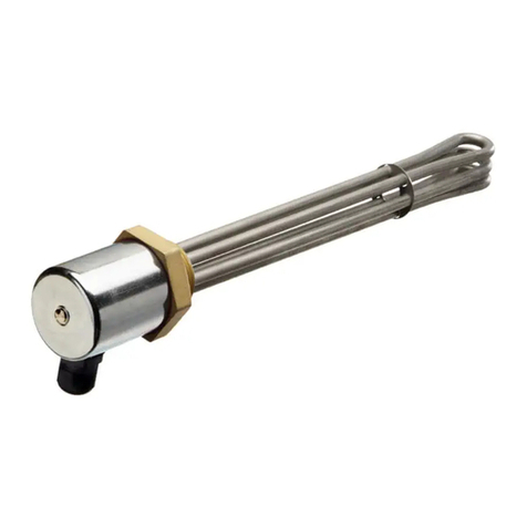
Schniewindt 93/F53-63 User manual

Page 1 of 10
Create date 22.02.2019
en
Only for use in a commercial environment!
Instruction manual
Article-number: 20153106330140
Cartridge type heater
Type : 93/F53-63
Output (W) : 1,000
Output tolerant (%) : +5/-10
Voltage : 400V 2~
Schniewindt GmbH & Co. KG
Schöntaler Weg 46
58809 Neuenrade, Germany
Phone: +49 2392 692-0
Fax: +49 2392 692-11
www.schniewindt.de
Translation
Created for the applicable standards in Germany

Page 2 of 10
Create date 22.02.2019
en
Table of Contents
1Information on the product.....................................................................3
2Intended use..........................................................................................3
3Safety.....................................................................................................4
4Connection and performance data.........................................................5
5Mounting instructions.............................................................................6
6Mounting................................................................................................6
7Installation..............................................................................................7
8Initial start-up .........................................................................................8
9Repair of failures....................................................................................8
10 Repair....................................................................................................9
11 Maintenance and servicing ....................................................................9
12 Dismantling............................................................................................ 9
13 Storage................................................................................................ 10
14 Disposal............................................................................................... 10

1 Information on the product
Page 3 of 10
Create date 22.02.2019
en
1 Information on the product
Designation : Cartridge type heater
Type : 93/F53–63
Min/max Temperature
At the connection head (°C) : -20/+40
In the connection area (°C) : -10/+80
Protection category : IP 65
Mounting direction :horizontal
Drawing number : 233.94.177.0
Notice
In addition, the cable glands can be used in areas with temperatures between -20 ° C to -40 ° C when
on site there is only static loads. Static load means that no other forces (shock, traction, pressure, etc.)
act on the properly assembled gland and its correctly fitted cable.
The screw insertion, the cable gland and the inserted cable must be in a resting position. A fixed cable
gland is observed. The cable gland must not be considered only as a single component, but the user
must take into account at the site, the sum of the prevailing ambient conditions.
At temperatures below -40 ° C, the sealing ring material CR / NBR begins to harden and the strong
polyamide PA6 used tend to embrittlement.
2 Intended use
The device is served for the warming up of liquids.
The device is used to heat the indicated medium.
The specified operating data must be observed.
Deviations are not permissible.
The electric heating insert of the device can be installed and developed, without the liquid must let
down from the container.

3 Safety
Page 4 of 10
Create date 22.02.2019
en
3 Safety
The instructions manual include important basic indications, which are to be observed during
installation and operating.
The instructions manual must be read and understood before installation and commissioning.
Keep the operating instructions for future reference.
Pass the manual to each subsequent owner and operator.
Do not make any modifications to the product.
Modifications can disable safety devices and cause personal injury and property damage.
Modifications lead to invalidation of conformity.
Note the mounting position of the device or direction of flow of the medium to be heated, when they
are given.
Carry out periodic inspections in accordance with national regulations.
Check safety-related components before starting up function.
Check monitoring equipment, (eg for temperature, minimum flow or level) when used as a safety
device in accordance with the relevant provisions on function.
Carry out an annual functional test of the safety devices.
Depending on the application and environment in a shorter interval.
This device is not suitable for use in areas threatened by explosive influences.
WARNING
Hot surfaces
Severe burns
- Do not touch
- Provide insulation

4 Connection and performance data
Page 5 of 10
Create date 22.02.2019
en
4 Connection and performance data
Electric data
Power (W) : 1,000
Voltage : 400 V 2~
Cable gland : M20x1.5
Ambient temperature -20°C to +100°C
Heating element
Type : cartridge with ceramic heating insert
Immersion length (mm) : 630
Thereof unheated length (mm) : 50
Cartridge tube -Ø (mm) : 52
Operating data
Medium : oil
Operating temperature (°C) : 40
Max. allowed. temperature (TS) (°C) : 80
Max. allowed. pressure (PS) (bar g) : 0.5
Connection head
Dimensions connection head (mm) : 108 x 108 x 90 red (RAL 3000)
Materials
Cartridge tube : steel
Flange : P250GH
Connection head : aluminium
Flange
DIN : EN 1092-1
Pressure stage : PN 6
Nominal width : DN 50
Temperature monitoring
Without temperature regulation
Without temperature limitation
An appropriate temperature regulation and / or temperature limitation is to be planned by the
builder/operator

5 Mounting instructions
Page 6 of 10
Create date 22.02.2019
en
5 Mounting instructions
During operation, the environment temperature at the connection head must not fall
below -20°C and the environment temperature of +40°C must not be exceeded.
Should the environment temperature deviate from these values, the device must be
switched off. (An appropriate room-temperature control must e.g. be provided).
The connection head must not be provided with thermal insulation, otherwise the
connection area is overheated.
Max. permissible temperature at the connection area: 80°C.
6 Mounting
Mounting position: horizontal
Installation note:
•When installing the device, make sure that it is not damaged. (Heating elements, …)
•Choose a seal witch is suitable for the medium.
•Choose suitable screws.
•Bolt the device flange with the installation flange.
•Check tightness.
•Re-tighten after the first heating (if necessary).
The device must be fixed tightly.
During operation the heating element must be covered by the medium to be heated,
otherwise overheating may occur.
Therefore, the customer must provide level monitoring ensuring that the device can only
be operated with sufficient covering (50 mm approx.) of the heating elements.
The electrical connection head and the cooling lenght (the range between flange and
connection head) may not be isolated.
The temperature regulation and / or temperature limitation is to be planned / connected by the
builder/operator

7 Installation
Page 7 of 10
Create date 22.02.2019
en
7 Installation
The work described in the following must be executed by an electrical engineer only.
To protect the device from damage, we recommend a fault current monitoring device shall be
provided.
TT- and TN systems: A fault current protection device should be installed. The calculation value of the
fault current must be set during commissioning.
IT system: An isolation control device has to be used, which interrupts the supply whenever the
insulation resistance amounts to no more than 50 Ohm/V, related to the calculation tension.
The supply voltage must correspond to the voltage indicated on the type plate.
For the selection of the cross-sections for connection, loads, fusing etc. the relevant legal
requirements must be observed (see a. o. VDE 0100, VDE 0298-4).
Electrical connection
1. Unscrew the cover.
2. Insert the cables through the cable glands into the connection head.
3. Tighten the nut of the cable gland to guarantee the strain relief and the protection mode.
(Cables and cable glands must be matched to guarantee the required protection mode.)
4. Connect cable according to the wiring diagram.
5. Check connections for tight fit.
6. Screw on cover.

8 Initial start-up
Page 8 of 10
Create date 22.02.2019
en
8 Initial start-up
Only turn on if the heated length is completely covered by the medium.
It is advisable provided an on-site level monitoring.
The connection head should not be isolated, otherwise the connection area can be
overheated.
Max. permissible temperature at the connection area: 80°C.
In a closed system, a pressure relief valve must be installed on site.
Please make sure to have closed the connection head properly.
Please make sure that the device is covered by the medium according to the requirements.
Set a temperature controller to the target temperature.
Guarantee that the temperature controller is duly attached.
Guarantee that the on-site temperature limitation is duly attached.
By a temperature limitation the medium and the device are protected against to high temperatures.
9 Repair of failures
The work described below must be executed by an electrical engineer only.
Failure: Device does not heat up
Repair: - Check fusing
- Control the supply voltage
- The temperature of the temperature controller is set too low.
Set temperature controller to the correct temperature.
- The on-site temperature-limiter switched off circuit.
Check reason, remove fault, reset temperature limiter.
Run the initial start-up procedure for the device after each repair of failures.

10 Repair
Page 9 of 10
Create date 22.02.2019
en
10 Repair
Before repairs only hold consultation with the manufacturer.
Trained personnel in compliance with common regulations do repairs
Use only by manufacturer authorized spare parts.
Improper repairs can result in personal injury and property damage
11 Maintenance and servicing
Execute an annual visual check of the device.
We recommend the checking of these tests and controls listed below at short intervals initially.
For perfect operation of the device the following aspects must be checked:
measure the insulation values
measure the resistance values (Ω)
measure and check the thermostat and / or limiter function
Visual inspection for damage
Visual inspection for deposits or incrustations on the heating elements
Visual inspection for leaks
Visual inspection of the electrical connection area
(Moisture, rust ... reduce the insulation value and must be removed.)
Deposits or incrustations on the heating elements can destroy the device and must be removed.
The cleaning must be do carefully, so that the surface is not damaged.
Carry out an annual functional test of the safety devices.
Depending on the application and environment in a shorter interval.
12 Dismantling
Switch off the system and secure to prevent unintentional restart.
Allow the device to cool to room temperature.
Uninstall and remove the connecting cable.
The system must be depressurised.
Drain the medium first and dispose of it properly

13 Storage
Page 10 of 10
Create date 22.02.2019
en
13 Storage
The store room must be dry and free of dust.
Make sure that the storing temperatures are between -40°C and +40°C.
Before storing, be sure that there is no humidity penetrated inside the connection area during transport
or interim storing.
All openings must be closely locked, in order to prevent a penetration from dust/moisture.
The connection area shall be tightly closed if necessary the cable entries must be equipped with
blinds.
Place a drying agent in the connection area to absorb existing humidity.
Use only chemically indifferent drying agents (e.g., silica gel).
Change the drying agent at the specified intervals. Observe the instructions of the drying agent
manufacturer.
During storage over a longer periods (several months), it is to be expected that the system-related
insulation resistance reduces.
14 Disposal
Remove any problematic deposits in accordance with local regulations.
Dispose of the device in accordance with local regulations.
Give metals and plastics sorted for recycling or scrapping.
This manual suits for next models
1
Table of contents
Other Schniewindt Heater manuals