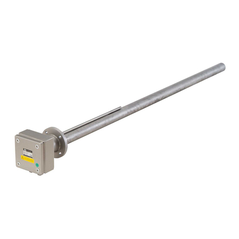
Schniewindt ERCH User manual

Page 1 of 17
Created on 23.07.2020
en
For operation in industrial environments only!
Operation Manual
Screw-in Heater
Type : ERCH/ERCT/ERCB/ERCTB/ERCU
ERKH/ERKT/ERKB/ERKTB/ERKU
Schniewindt GmbH & Co. KG
Schöntaler Weg 46
58809 Neuenrade, Germany
Tel.: +49 2392 692-0
Fax.: +49 2392 692-11
www.schniewindt.de
Translation
Created according to regulations applicable in Germany.
ERCH/ERKH ERCT/ERKT
ERCB/ERKB
ERCTB/ERKTB

Page 2 of 17
Created on 23.07.2020
en
Table of contents
Intended use .......................................................................................... 3
General SafetyInstructions ..................................................................... 3
Identify unit ............................................................................................ 4
Type code .............................................................................................. 4
Product specifications ............................................................................ 5
Mounting instructions ............................................................................. 6
Mounting ................................................................................................ 6
Installation general ................................................................................. 7
8.1. Installation ERCH / ERKH ...................................................................... 8
8.2. Installation of units with rotatable element ............................................. 9
8.3. Installation of units with a red hood ...................................................... 10
Commissioning .................................................................................... 10
Controller setting .................................................................................. 11
Limiter setting ...................................................................................... 12
11.1. Limiter reset ......................................................................................... 12
Units with limiter, internal setting ERCB / ERKB .................................. 13
Units with controller and limiter ERCTB / ERKTB ................................ 14
Units with dry-running protection ERCU / ERKU ................................. 15
Repairs ................................................................................................ 15
Remedying malfunctions ...................................................................... 16
Repairs and maintenance .................................................................... 16
Dismantling .......................................................................................... 17
Storage ................................................................................................ 17
Disposal ............................................................................................... 17

1 Intended use
Page 3 of 17
Created on 23.07.2020
en
Intended use
The unit is used for heating liquid or gaseous media.
The medium, the operating conditions and the installation position are tailored to the respective
application and listed in the order confirmation.
The unit is used for heating the medium specified in the order confirmation.
The operating conditions of the order confirmation must be observed.
Deviations from this are not allowed.
General SafetyInstructions
This Operation Manual contains basic instructions which must be followed during installation and
operation. The operation manual must be read and understood prior to assembly and commissioning.
Keep the Operation Manual for later use.
Pass on the Operation Manual to all subsequent owners and operating companies.
Do not make any modifications to the unit.
Modifications can disable safety devices and cause personal injury and property damage.
Modifications lead to invalidation of conformity.
If an installation position or flow direction of the medium to be heated is specified, this must be taken
into account.
Periodic inspections must be carried out in compliance with the national provisions.
The function of safety-relevant components must be checked prior to commissioning.
Any monitoring devices (e.g. for temperature, minimum flow rate or level) employed as safety devices
must be checked to ensure that they function properly in compliance with the relevant provisions.
The unit is not suitable for use in potentially explosive atmospheres.

3 Identify unit
Page 4 of 17
Created on 23.07.2020
en
Identify unit
1 Type designation
2 Production number (Please specify when making inquiries)
3 Type code (see point )
4 Installation length in cm
5 Output in kW
Type code
ER***/**-**
Output in kW
Installation length in cm
No temperature monitoring
H = Hood
With temperature monitoring:
T = Thermostat controller
L = Limiter
TL = Controller and limiter
U = Dry-running protection
Tubular heating element material:
C = Steel
K = Copper
Type series
Screw-in Heater
Tubular heating element
1
3
4
5
2

5 Product specifications
Page 5 of 17
Created on 23.07.2020
en
Product specifications
Name : Screw-in heater
For technical details see order confirmation.
Note:
Cable gland temperature range : -20°C (dynamic) to +100°C.
-40°C (static, briefly)
The cable glands can be used at temperatures of between -20°C and -40°C only if static stress is
present at the place of use. Static stress means that no other forces (impact, tension, pressure, etc.)
may act on the correctly mounted cable gland and its correctly installed line.
The screwing point, cable gland and inserted line must be in an idle position. A fixed cable gland must
be used. Instead of considering the cable gland as just a stand-alone component, the user must take
the sum total of the prevailing ambient conditions into account at the place of use.
At temperatures below -40°C, the sealing ring material CR/NBR starts to harden significantly and the
polyamide PA6 used tends to become brittle.
Temperature recording
The units must not be operated without appropriate temperature recording.
Install a suitable temperature control and/or limit on site if this is not installed by the manufacturer.
Refer to your order confirmation for the setting values.

6 Mounting instructions
Page 6 of 17
Created on 23.07.2020
en
Mounting instructions
During operation, the minimum or maximum ambient temperatures at the connection
hood specified in these instructions must not be exceeded or fallen short of. If the
ambient temperature is different, the unit must be switched off (e.g. a suitable room
temperature controller or similar unit should be provided).
The connection head must not be insulated.
Max. permissible temperature in the connection area 80°C.
During operation, the unit must be covered by the medium being heated to prevent the
unit from overheating.
For this reason, a level monitor should be provided on-site in case of stationary media
to ensure that the unit can be operated only when the heating element is adequately
covered (approx. 50 mm).
In the case of flowing media, a flow monitor should be installed on site in the system.
The customer must protect the unit against overheating by appropriate flow and return of
the medium. Operation with non-flowing or incorrect medium as well as with a
system/housing that is not completely filled is forbidden, even for test purposes.
The medium must cover the heating pipe by a minimum of 50 mm. Air in the
system/housing (in the case of liquids) or dry heating can cause an irreparable defect of
the heating elements.
Mounting
Installation position horizontal
Mounting instruction:
Use a suitable open-ended spanner.
Use a suitable seal
The operator is responsible for the compatibility between the medium and the container
or seal material.
Position the open-ended spanner only on the hexagon of the threaded flange.
Never apply force via the connection head.
The thread must be in perfect condition.
Firmly screw in the threaded flange.
Retighten after heating up for the first time. (if necessary)

8 Installation general
Page 7 of 17
Created on 23.07.2020
en
Installation general
The activities described below are reserved for qualified electricians.
The provisions of the DIN VDE 0100 (low voltage systems) and DIN VDE 0298-4 (high-voltage
systems) or the locally applicable regulations must be observed when planning projects,
selecting and installing the electrical system.
The electrical connections must be made according to the relevant VDE provisions and/or the
locally applicable regulations.
We recommend that a fault current monitoring device be provided.
The connection voltage must match the voltage stated on the rating plate.
Before opening the unit, it is absolutely essential to ensure that no voltage is present.

8.1 Installation ERCH / ERKH
Page 8 of 17
Created on 23.07.2020
en
8.1. Installation ERCH / ERKH
The position of the cable gland can be adapted.
To do this, loosen the sleeve nut in the hood.
However, the hood may only be rotated a maximum of 45° to the right or left.
1. Loosen the sleeve nut
2. Remove the hood.
3. Make sure that the earthing cable has not become detached.
Max. tensile load of the earthing cable 10 N.
4. Insert the cables through the cable glands and into the connection hood. Tighten the cap nut
by hand by turning it to the right while holding down the nut below it. Tighten with the
specified torque to guarantee strain relief and protection class. (Cables and connections
must be compatible in order to guarantee the required protection class.)
5. Connect the cable according to the enclosed wiring diagram.
6. The customer must provide earthing with an open cable lug on the threaded flange. To do
this, loosen the countersunk screw in the spanner flat and push on the cable lug.
7. Check the connections for tightness.
8. Attach the hood
9. Fasten using the sleeve nut.

8.2 Installation of units with rotatable element
Page 9 of 17
Created on 23.07.2020
en
8.2. Installation of units with rotatable element
The position of the cable bushing can be adapted.
To do this, loosen the threaded pins, but do not unscrew them completely.
However, the connection head may only be rotated a maximum of 45° to the
right or left.
10. For units with an external adjustment, pull off the scale lever.
11. Loosen the 2 countersunk screws on the front
12. Remove the hood.
13. Make sure that the earthing cable has not become detached.
Max. tensile load of the earthing cable 10 N.
14. Insert the cables through the cable glands and into the rotatable element.
15. Tighten the cable gland nut to guarantee strain relief and protection class. (Cables and
connections must be compatible in order to guarantee the required protection class.)
16. Connect the cable according to the enclosed wiring diagram. The wiring diagram is located
in the connection hood.
17. The customer must provide earthing with an open cable lug on the threaded flange. To do
this, loosen the countersunk screw in the spanner flat and push on the cable lug.
18. Check the connections for tightness.
19. Attach the hood
20. Attach the hood with the 2 countersunk screws.
21. For units with an external adjustment, put the scale lever back on

8.3 Installation of units with a red hood
Page 10 of 17
Created on 23.07.2020
en
8.3. Installation of units with a red hood
1. Unscrew the cover of the connection head.
2. Make sure that the earthing cable has not become detached.
Max. tensile load of the earthing cable 10 N.
3. Insert the cable through the cable gland and into the connection head.
4. The cable gland nut must be tightened to guarantee the strain relief and protection class.
(Cables and connections must be compatible in order to guarantee the required protection
class.)
5. Connect the cable according to the enclosed wiring diagram. The wiring diagram is located in
the connection hood.
6. The customer must provide earthing with an open cable lug on the threaded flange. To do this,
loosen the countersunk screw in the spanner flat and push on the cable lug.
7. Check the connections for tightness.
8. Screw on the cover of the connection head.
Commissioning
1. Before switching on, make sure that all lines are connected properly.
2. Before switching on, make sure that the heated length is fully covered by the medium.
3. Make sure that the temperature limiter (installed or on-site) has been properly connected.
4. Set the temperature controller (installed or on-site) to the required temperature.
5. After the controller has been set, the connection head must be properly sealed.

10 Controller setting
Page 11 of 17
Created on 23.07.2020
en
Controller setting
The medium temperature is set by the integrated temperature controller.
The integrated controller is set to the desired temperature by turning the scale lever.
The setting range of the scale lever can be found on the attached scale or in your order confirmation.
ERCT / ERKT

11 Limiter setting
Page 12 of 17
Created on 23.07.2020
en
Limiter setting
The integrated temperature limiter (TL) protects both the medium and the unit from excessive
temperatures.
The TL is set to the smallest value at the factory.
Caution:
The limiter setting takes place under voltage.
DANGER
Lethal danger from electric current
Death/serious bodily injuries/material damage
The TL can be set as follows:
Set the limiter to maximum.
You can do this by turning the adjusting spindle all the way to the right.
Heat up heater until the nominal operating temperature
Turn the adjusting spindle slowly to the left
Define trigger temperature of the TL under these operating conditions
Set the limiter temperature approx. 20 to 30°C above this value using the attached temperature scale.
Release limiter once again by pressing the release button.
11.1. Limiter reset
The limiter has triggered and must be reset.
To do this, open the connection hood.
Unlock the TL by pressing the restart button.
To do this, press the restart button.

12 Units with limiter, internal setting ERCB / ERKB
Page 13 of 17
Created on 23.07.2020
en
Units with limiter, internal setting ERCB / ERKB
ERCB / ERKB

13 Units with controller and limiter ERCTB / ERKTB
Page 14 of 17
Created on 23.07.2020
en
Units with controller and limiter ERCTB / ERKTB
Figure 1 Figure 2 Figure 3
Figure 1:
The 3-pin regulator/limiter combination is available in two versions:
Limiter set permanently to 92°C, controller adjustable within the range from 30°C to 78°C
Limiter set permanently to 100°C, controller adjustable within the range from 30°C to 85°C
Figure 2:
Regulator with external setting, limiter with internal setting.
The limiter setting and controller range can be found on the connection diagram or in your order
confirmation.
Figure 3:
Regulator and limiter with internal setting.
The limiter setting and controller range can be found on the connection diagram or in your order
confirmation.

14 Units with dry-running protection ERCU / ERKU
Page 15 of 17
Created on 23.07.2020
en
Units with dry-running protection ERCU / ERKU
Intended use:
Units with dry-running protection are used to heat water in containers and storage tanks with strongly
fluctuating filling levels.
Operating conditions: max. 100°C at max. 10 bar
Other operating conditions are only permissible if they are in your order confirmation.
The integrated dry-running protection prevents the unit from burning out if the filling level is too low.
Mounting
The units must be screwed horizontally into a hole with an internal thread G1 ½ ".
The dry-running protection sensor must be at the highest point of the installed unit.
ERCU / ERKU
Repairs
Contact the manufacturer before carrying out repairs.
Repairs must be carried out by trained personnel in compliance with established regulations
Only use spare parts approved by the manufacturer.
Improper repairs can lead to personal injury and damage to property

16 Remedying malfunctions
Page 16 of 17
Created on 23.07.2020
en
Remedying malfunctions
The activities described below are reserved for qualified electricians.
Malfunction: Unit does not warm up
Remedy: - Check fuses
- Check connection voltage
Switch off the system and secure it to prevent unintentional restart. Open the
connection head and inspect the heating insert for electrical continuity. In the absence
of continuity, contact the manufacturer to request a new heating insert. The part can
be replaced without draining the medium.
Restart the unit once the malfunction has been remedied.
Repairs and maintenance
Visually inspect the unit every year.
We recommend initially carrying out the inspections and checks stated below at short intervals.
To ensure faultless operation, the unit must be examined as follows:
Measure the insulation values.
Measure the resistance values (Ω).
Check that the temperature regulator and/or limiter is functioning properly, test.
Visual inspection for damage.
Visual inspection for deposits or encrustations on the heating elements.
Visual inspection for leaks.
Visual inspection of the electrical connection space
(moisture, rust, .. insulation values reduced and must be removed.)
Deposits or encrustations on the heating elements can destroy the unit and must be removed.
Cleaning must be carried out carefully to prevent damage to the surface of the heating elements.
Carry out an annual function inspection of the safety devices.
At shorter intervals, depending on the level of use and ambient conditions.

18 Dismantling
Page 17 of 17
Created on 23.07.2020
en
Dismantling
Switch off the system and secure it to prevent unintentional restart.
Allow the unit to cool down to room temperature.
Disconnect connection cable and remove.
The system must be depressurised.
Drain the medium beforehand and dispose of accordingly.
Storage
The storage room must be dry and dust-free.
Make sure that the storage temperatures are between -40°C and +40°C.
Before storing, it must be ensured that that no moisture has penetrated into the terminal compartment
during transportation or during intermediate storage.
All openings must be sealed tightly in order to avoid penetration of dust/moisture.
The terminal compartment must be sealed tightly and the cable entries must be provided with blind
plugs, if applicable.
Insert a suitable drying agent in the terminal compartment to absorb any existing moisture.
Only use chemically neutral drying agents (e.g. silica gel).
Replace the drying agent at the prescribed intervals. Observe the instructions of the drying agent
manufacturer.
When storing over longer periods of time (several months), the insulation resistance can be expected
to decrease due to the system.
The heater may only be put into operation after ensuring that the insulation resistance in accordance
with the standard DIN 44874, Section 1, Paragraph 5.3 is greater than
Riso ≥ 2 MΩ
Number of installed tubular heating
elements
Measured in cold condition with 500V DC voltage.
Disposal
Remove problematic deposits in accordance with local regulations.
Dispose of the unit in accordance with local regulations.
Clearly separate metals and plastics for recycling or scrapping.
This manual suits for next models
9
Table of contents
Other Schniewindt Heater manuals