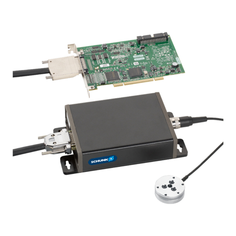
SCHUNK APS-ME1 User instructions

Translation of Original Operating Manual
Assembly and Operating Manual
APS-ME1
Electronic processor

Imprint
2
01.00 | APS-ME1 | Assembly and Operating Manual | en | 1415570
Imprint
Copyright:
This manual is protected by copyright. The author is SCHUNK GmbH & Co. KG. All rights
reserved. Any reproduction, processing, distribution (making available to third parties),
translation or other usage - even excerpts - of the manual is especially prohibited and
requires our written approval.
Technical changes:
We reserve the right to make alterations for the purpose of technical improvement.
Document number: 1415570
Version: 01.00|30/09/2019|en
© SCHUNK Electronic Solutions GmbH
All rights reserved.
Dear Customer,
thank you for trusting our products and our family-owned company, the leading
technology supplier of robots and production machines.
Our team is always available to answer any questions on this product and other solutions.
Ask us questions and challenge us. We will find a solution!
Best regards,
Your SCHUNK team
SCHUNK Electronic Solutions GmbH
Am Tannwald 17
D-78112 St. Georgen
Tel. +49-7725-9166-0
Fax +49-7725-9166-5055
schunk.com

Table of Contents
01.00 | APS-ME1 | Assembly and Operating Manual | en | 1415570
3
Table of Contents
1 General.................................................................................................................... 4
1.1 About this manual ................................................................................................ 4
1.1.1 Applicable documents ..............................................................................4
1.2 Scope of delivery .................................................................................................. 4
1.3 Warranty .............................................................................................................. 4
2 Basic safety notes ................................................................................................... 5
2.1 Appropriate use.................................................................................................... 5
2.2 Inappropriate use ................................................................................................. 5
2.3 Environmental and operating conditions ............................................................. 5
2.4 Constructional changes ........................................................................................ 5
2.5 Personnel qualification......................................................................................... 6
3 Technical Data APS-M1E .......................................................................................... 7
4 Assembly and settings ............................................................................................. 8
4.1 Mounting and connecting the electronic processor............................................. 8
4.1.1 Connection diagram .................................................................................9
4.2 Calibrating the electronic processor................................................................... 10

General
4
01.00 | APS-ME1 | Assembly and Operating Manual | en | 1415570
1 General
1.1 About this manual
This manual contains important information for a safe and
appropriate use of the product.
This manual is an integral part of the product and must be kept
accessible for the personnel at all times.
Before starting work, the personnel must have read and
understood this operating manual. Prerequisite for safe working is
the observance of all safety instructions in this manual.
1.1.1 Applicable documents
• General terms of business
• Catalog data sheet of the purchased product
• Assembly and Operating Manual of the sensors
The documents listed here, can be downloaded on our homepage
www.schunk.com
1.2 Scope of delivery
The scope of delivery includes
• Electronic processor APS-M1E
• Accessory pack
1.3 Warranty
If the product is used as intended, the warranty is valid for 24
months from the ex-works delivery date under the following
conditions:
• Observe the applicable documents, Applicable
documents [}4]
• Observe the ambient conditions and operating conditions,
Environmental and operating conditions [}5]

Basic safety notes
01.00 | APS-ME1 | Assembly and Operating Manual | en | 1415570
5
2 Basic safety notes
2.1 Appropriate use
The complete APS-M1 system, consisting of electronic processor
and sensor, is intended for displacement measurements, e.g.
–for attachment to grippers for measuring and control tasks,
–for installation in measuring stands and measuring devices,
–for testing and gauging workpieces and production processes in
a clean environment.
Since the system is not calibrated or gauged, the user must
calibrate the system or have it gauged for corresponding
applications at regular intervals.
• The electronic processor is intended for installation in a switch
cabinet. The applicable guidelines must be observed and
complied with.
• The product may only be used within the scope of its technical
data, Technical Data APS-M1E [}7].
2.2 Inappropriate use
The product is not a safety component in accordance with the EC
Machine Directive 2006/42/EC and must not be used in safety-
relevant parts of machine control units.
2.3 Environmental and operating conditions
Required ambient conditions and operating conditions
Incorrect ambient and operating conditions can make the product
unsafe, leading to the risk of serious injuries, considerable material
damage and/or a significant reduction to the product's life span.
• Make sure that the product is used only in the context of its
defined application parameters, Technical Data APS-M1E
[}7].
• Make sure that the environment is free from splash water and
vapors as well as from abrasion or processing dust. Exceptions
are products that are designed especially for contaminated
environments.
2.4 Constructional changes
Implementation of structural changes
By conversions, changes, and reworking, e.g. additional threads,
holes, or safety devices can impair the functioning or safety of the
product or damage it.
• Structural changes should only be made with the written
approval of SCHUNK.

Basic safety notes
6
01.00 | APS-ME1 | Assembly and Operating Manual | en | 1415570
2.5 Personnel qualification
Inadequate qualifications of the personnel
If the personnel working with the product is not sufficiently
qualified, the result may be serious injuries and significant
property damage.
• All work may only be performed by qualified personnel.
• Before working with the product, the personnel must have read
and understood the complete assembly and operating manual.
• Observe the national safety regulations and rules and general
safety instructions.

Technical Data APS-M1E
01.00 | APS-ME1 | Assembly and Operating Manual | en | 1415570
7
3 Technical Data APS-M1E
Designation APS-M1E
Ambient temperature [°C]
Min.
Max.
0
+60
Temperature drift [%/°C] 0.05
Nominal voltage [VDC]
Min.
Max.
24
21
27
Max. power consumption [W] 2.5
Oscillator voltage [VSS Sine] 7
Oscillator Frequency [Hz] 4800 ±8%
Output 1 [V] 0...10
permissible load RL [kOhm] ≥ 2
Output 2 [mA] 4...20
Load resistance [Ohm] 0...250
IP rating 20

Assembly and settings
8
01.00 | APS-ME1 | Assembly and Operating Manual | en | 1415570
4 Assembly and settings
4.1 Mounting and connecting the electronic processor
ØMount the electronic processor in the control cabinet.
ØIf the length of the sensor cable is not sufficient, use a cable
extension (see operating manual of the sensor).
✓Maximum permissible cable length between sensor and
electronic processor: 10m.
ØConnect the sensor or extension cable to the terminals of the
electronic processor, Connection diagram [}9].
ØConnect the shield of the sensor cable to the ground terminal.
ØConnect the power supply to the evaluation electronics.
ØConnect the multimeter or automation device to the standard
signal output(0-10V or 4-20mA) used.
ØAdjust the standard signal output to the gripper stroke,
Calibrating the electronic processor [}10].
ØConnect the cable shield to the functional earth(FE) of the
electronic processor.
ØConnect shielded cable between electronic processor and
automation device, Connection diagram [}9].
✓Maximum permissible cable length: 3m.
ØFine-tune the standard signal.

Assembly and settings
01.00 | APS-ME1 | Assembly and Operating Manual | en | 1415570
9
4.1.1 Connection diagram
Connection diagram
1 Connector housing 4 Electronic processor
2 Socket housing 5 Cable extension
3 Automation device 6 Sensor
Wire colors:
bu Blue gr Grey
wh White pk Pink
rd Red ye Yellow
bk Black

Assembly and settings
10
01.00 | APS-ME1 | Assembly and Operating Manual | en | 1415570
4.2 Calibrating the electronic processor
Electronic processor
1 0-point
Voltage output
4 Amplification
Current output
2 Amplification
Voltage output
5 Activate voltage output
3 0-point
Current output
6 Activate current output
■Gripper is mounted and connected.
■Sensor is mounted and connected.
■Electronic processor is mounted and connected.
■Electronic processor is at operating temperature.
ØSet the standard signal output(0-10V or 4-20mA) at the DIP
switches. Make sure that the unused standard signal output is
deactivated.
ØOpen the gripper. Insert the gauge block corresponding to the
minimum gripper stroke. Close the gripper.
ØSet the standard signal value corresponding to the inserted
gauge block at the 0-point potentiometer.
ØOpen the gripper. Insert the gauge block corresponding to the
maximum gripper stroke. Close the gripper.
ØSet the standard signal value corresponding to the inserted
gauge block on the gain potentiometer.

Assembly and settings
01.00 | APS-ME1 | Assembly and Operating Manual | en | 1415570
11
Example for adjusting the electronic processor
■Gripper overall stroke: 0 ... 33mm
■Standard signal output: 0 ... 10V
■Voltage / mm: 0.303030303 V/mm
ØOpen the gripper. Insert gauge block with 1mm thickness. Close
the gripper.
ØSet 0.303V on the 0-point potentiometer.
ØOpen the gripper. Insert gauge block with 33mm thickness.
Close the gripper.
ØSet 10V on the gain potentiometer.

12
01.00 | APS-ME1 | Assembly and Operating Manual | en | 1415570
Table of contents
Other SCHUNK Computer Hardware manuals