manuals.online logo
Brands
  1. Home
  2. •
  3. Brands
  4. •
  5. Bosch
  6. •
  7. Industrial Equipment
  8. •
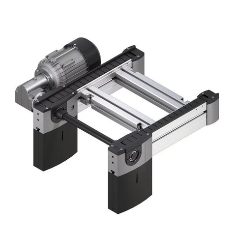
  9. Bosch BS 2/R User manual

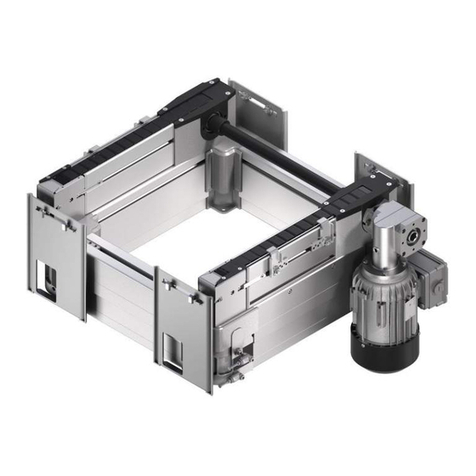
Bosch BS 2/R User manual

1
de
en
fr
it
es
pt
Bandstrecke BS 2/R
Belt section
Section à bande
Tratto a nastro
Tramo de cinta
Via de esteira
Montagetechnik
Assembly technology
Technique de montage
Tecnica di montaggio
Técnica de montaje
Técnica de montagem
BS 2/R (3 842 999 904)
2
Sicherheitshin eise!
Safety instructions!
Consignes de sécurité !
y
Achtung!
Vor Installation, Inbetriebnahme, War-
tung und Instandsetzung ist die Be-
triebs- und Montageanleitung, vor allem
die Sicherheitsvorschriften zu lesen und
zu beachten.
urchführung der Arbeiten nur durch
geschultes, eingewiesenes Fachperso-
nal!
Alle Sicherheitsabdeckungen, die bei
Wartungsarbeiten oder Montage ent-
fernt wurden, müssen vor der Inbetrieb-
nahme wieder angebracht werden!
Elektrische Anschlüsse nach der ent-
sprechenden nationalen Vorschrift. Für
eutschland: V E-Vorschrift V E
0100!
Vor allen Instandsetzungs-, und
Wartungsarbeiten sind die Energiezu-
führungen (Hauptschalter, ruck-
minderventil etc.) abzuschalten!
Außerdem sind Maßnahmen erforder-
lich, um ein unbeabsichtigtes Wieder-
einschalten zu verhindern, z. B. am
Hauptschalter ein entsprechendes
Warnschild "Wartungsarbeiten",
"Instandsetzungsarbeiten" etc. anbrin-
gen!
ie bestimmungsgemäße Verwendung
der BS 2/R ist der Werkstücktransport
auf Bosch-Werkstückträgern WT 2 im
Bosch-Transfersystem TS 2plus. Max.
zulässige WT-Last 70kg. Max. zulässige
Gesamtlast der BS 2/R 200kg.
ie BS 2/R ist nicht begehbar!
Haftung:
Bei Schäden, die aus nicht bestim-
mungsgemäßer Verwendung und aus
eigenmächtigen, in dieser Anleitung
nicht vorgesehenen Eingriffen entste-
hen, erlischt jeglicher Gewährleistungs-
und Haftungsanspruch gegenüber dem
Hersteller.
Garantieausschluss:
Bei Nichtverwendung von Originaler-
satzteilen erlischt der Garantiean-
spruch!
TS 2plus-Ersatzteilliste-Nr.:
3 842 526 720
Umweltschutz:
Beim Austausch von Schadteilen ist auf
eine sachgerechte Entsorgung achten!
yy
Warning!
The operating and assembly instruc-
tions and especially the safety regula-
tions must be read and observed before
installation, start-up, maintenance and
repairs.
The work should only be performed by
qualified and specially trained person-
nel!
All security coverings that have been re-
moved during repair works have to be
reinstalled before comissioning!
All electrical connections must be made
in accordance with the applicable na-
tional regulations. For Germany: regula-
tion V E 0100 (V E, German Associa-
tion of Electricians)!
The current must always be switched
off (at main switch, pressure relief valve
etc.) before maintenance and repair
work!
Take precautions to prevent inadvertent
restoration of power, e.g. by hanging a
suitable warning sign at the main
switch, such as: "Maintenance work in
progress", or "Repair work in progress"!
The BS 2 /R is only designed for the
transport of workpiece pallets in the
TS 2plus transfer system with
Bosch WT 2 workpiece pallets.
Max. permissible WT load: 70kg.
Max. permissible total weight of
BS 2/R: 200kg.
Walking on the BS 2/R is not permit-
ted!
Liability:
In no event can the manufacturer ac-
cept warranty claims or liability claims
for damages arising from improper use
of the appliance or from intervention in
the appliance other than that described
in this instruction manual.
Exclusion of guarantee:
The manufacturer can accept no guar-
antee claims if non-original spare parts
have been used!
TS 2plus replacement parts list no.:
3 842 526 720
Environmental protection:
Always dispose of damaged parts in the
correct manner when replacement work
is complete!
yyy
Attention !
Avant l’installation, la mise en service, la
maintenance et les réparations, lire et
respecter les instructions d’utilisation et
de montage, et surtout les consignes
de sécurité.
Les travaux ne doivent être effectués
que par des personnes agréées et com-
pétentes !
Avant la mise en service, remettre en
place tous les carters de sûreté enlevés
pour les travaux de maintenance !
Les branchements électriques doivent
être conformes à la réglementation na-
tionale. Pour l'Allemagne : norme
V E 0100!
Avant d'effectuer des réparations ou
des travaux de maintenance, couper
l'alimentation en énergie (interrupteur
principal, mano-détendeur etc.) !
'autre part, prendre toutes les mesu-
res nécessaires pour éviter une remise
en marche accidentelle, en apposant
par exemple près de l'interrupteur prin-
cipal un panneau d'avertissement "tra-
vaux de maintenance", "réparations"
etc. !
Le convoyeur transversal électrique
BS 2/R n'a été conçu que pour le trans-
port de pièces dans le système de
transfert TS 2plus avec les palettes
porte-pièces WT 2 de Bosch.
Charge max. autorisée sur la WT :
70 kg.
Charge max. autorisée sur la BS 2/R :
200 kg.
Il est interdit de monter sur le BS 2/R !
Responsabilité :
Le fabricant décline toute responsabilité
et exclut toute réclamation concernant
les dommages dus à une utilisation non
conforme ou suite à des modifications
effectuées sans autorisation et non pré-
vues ci-contre.
Exclusion de garantie :
En cas de non-utilisation des pièces dé-
tachées d'origine, le constructeur ex-
clut toute responsabilité !
N° liste de pièces de rechange
TS 2plus : 3 842 526 720
Protection de l'environnement :
Veiller à ce que les pièces
endommagées soient éliminées en
toute conformité !
3
de
en
fr
it
es
pt
Anlieferungszustand/Lieferumfang
Delivery condition/Scope of delivery
Etat à la livraison/Fournitures
y
Fig. 1:
Komplett montiert,
mit Transportsicherung " "!
*)Standardversion: Motoranbau rechts
außen, liegend.
Befestigungsmaterial muß separat
bestellt werden (siehe Zubehör)
“ “ = Transportsicherung
“ “ = Transport retainer
“ “ = Sûreté de transport
yy
Fig. 1:
Fully assembled, with transport
retainer " "!
*)Standard version: motor mounting
outside right, horizontal.
Fastening hardware must be ordered
separately (see accessories below).
yyy
Fig. 1:
Entièrement monté,
avec sureté " " pour le transport!
*)Version standard : montage du moteur
à l’extérieur, à droite, à plat.
Le matériel de fixation doit être com-
mandé séparément (cf. Accessoires)
Fig. 1
Getriebe-Motoranbau außen R* und L, liegend* und hängend
Gearbox - motor mounting outside right R* and left L, horizontal*
and hanging
Montage du moto-réducteur à l’extérieur, à droite R* et à gauche L,
à plat* et suspendu
Getriebe-Motoranbau innen R, hängend
Gearbox - motor mounting, inner right, hanging
Montage du moto-réducteur à l’intérieur, à droite, suspendu
*)Standardversion
*)Standard version
*)Version standard
4
Fig. 2 Fig. 3
SZ 2
y
Für den Einbau der BS 2/R
z ischen Strecken ST 2:
Verbindungssatz 3 842 528 192
(Fig. 2, muss separat bestellt werden).
Für die Montage auf Stützen SZ 2:
(Fig. 3). Auswahl und Bestell-Nrn. siehe
TS 2plus-Katalog.
Demontage erkzeug 8 981 010 511
für Staurollenkette und
Kettenschloss 3 842 523 919 (Fig. 4)
(siehe TS 2plus-Katalog).
yy
For installing BS 2/R
bet een conveyor sections ST 2:
Connecting kit 3 842 528 192 (Fig. 2,
must be ordered separately).
For installation on leg sets SZ 2:
(Fig. 3). For selection and part numbers
please refer to TS 2plus catalogue.
Removal tools 8 981 010 511 for
accumulation roller chain and master
link 3 842 523 919 (Fig. 4)
(see TS 2plus catalogue).
yyy
Pour le montage de BS 2/R entre les
sections ST 2 :
kit de montage 3 842 528 192 (Fig. 2,
à commander séparément).
Pour le montage sur les supports
SZ 2 :
(Fig. 3). Pour les différentes
options et les numéros de référence,
consulter le catalogue TS 2plus.
Outil de démontage 8 981 010 511
pour chaîne à galets d’accumulation
et maillon raccord 3 842 523 919
(Fig. 4)
(Cf. catalogue TS 2plus).
Zubehör
Accessories
Accessoires
Fig. 4
8 981 010 511
3 842 523 919
M8x25
(4x)
(4x)
(4x)
(4x)
M8 (8x)
M8x30
de
en
fr
it
es
pt
Hauptabmessungen/Funktionsmaße
Main dimensions/Functional dimensions
Mesures principales/Dimensions fonctionelles
160 107
170
70
122
60
l
105,4
43,5
61,7
bWT
bWT
bWT
bWT
203
138
+40
+178
+178
Fig. 05
6
y
Allgemeines:
as Befestigen der Baueinheit BS 2/R
im Transfersystem erfolgt nach dem
Hammerschraubenprinzip.
Max. Anzugsdrehmoment 25 Nm.
A = Einsatzlage
B = Klemmlage
C = Anlage in Nut
( rehmomentstütze)
Transportsicherung " " erst nach dem
Einbau entfernen (Fig. 6)!
yy
General:
The BS 2/R unit is secured in the
transfer system using the T-bolt
principle.
Max. torque 25 Nm.
A = Position on insertion
B = Clamping position
C = Arrangement in groove
(torque support)
Only remove transport retainer " " after
installation! (Fig. 6)
yyy
Généralités :
La fixation du composant BS 2/R sur le
système de transfert est assurée suivant
le principe de la vis à tête rectangulaire
(Fig. 4).
Couple de serrage max. 25 Nm.
A = Position d'insertion
B = Position de serrage
C = Position dans la rainure
(support du couple)
Ne retirer la sureté de transport" "
qu’après le montage ! (Fig. 6)
Einbau in das Transfersystem
Installing in the transfer system
Montage dans le système de transfert
Fig. 6
7
de
en
fr
it
es
pt
Werkzeuge und Hilfsmittel
Tools and aids
Outils et dispositifs auxiliaires
y
Für die Montage wird empfohlen fol-
gende Werkzeuge und Hilfsmittel be-
reit zu legen:
1 Sechskantschrauben-Schlüssel-
satz, vorzugsweise
rehmomentschlüssel
2 Innensechskant-Schlüsselsatz, vor-
zugsweise rehmomentschlüssel
3 Schraubendreher-Satz
4 Flachzange, Rundzange
5 Wellensicherungszange Größe 1
6 Wasserwaage, Mindestlänge 600
mm.
7 Richtschnur
8 Flachfeile, fein
9 Flaschenzug o. ä. Hebewerkzeug.
yy
It is recommended to have the
following tools and aids ready for use
for assembly:
1 Wrench set, perferably with torque
meter
2 Allen key set, perferably with
torque meter
3 Screwdriver set
4 Flange pliers, round pliers
5 Shaft holding pliers, size 1
6 Bubble level, min. length:
600 mm.
7 Snap marking string
8 Flat file, fine
9 Hoist or other lifting tool.
yyy
Pour procéder au montage, nous
recommandons d’utiliser les outils et
dispositifs auxiliaires suivants :
1 Jeu de clés pour vis hexagonales,
de préférence clés
dynamométriques
2 Jeu de clés pour vis à 6 pans
creux, de préférence clés
dynamométriques.
3 Jeu de tournevis
4 Pince plate, pince ronde
5 Pince à circlips, taille 1
6 Niveau à bulle, longeur minimale
600 mm.
7 Cordeau marqueur
8 Lime plate, fine
9 Poulie ou outil de levage similaire.
8
y
er Einbau der BS 2/R in die Strecke
ST 2 muss aus Gründen der Funktions-
sicherheit und zur Verhinderung des
vorzeitigen Verschleißes nach Flucht
und Waage, rechtwinklig und
achsparallel durchgeführt werden!
Transportsicherung „ “ erst nach dem
Einbau entfernen!
1. Zur Montage muss die äußere
Schutzkastenhälfte entfernt werden.
2. Vor dem Einbau der BS 2/R zwi-
schen die Strecken ST 2 muss am
Schutzkasten an der Perforation „X“
nach Bedarf ein entsprechendes
Stück herausgebrochen werden.
3. en durch das Herausbrechen ent-
stehenden Grat (mit einer Feile) ent-
fernen!
4. Verbindungssatz nach Montagean-
leitung 3 842 528 294 und Fig. 8
einbauen.
5. Vor Inbetriebnahme Schutzkasten
anbringen!
yyy
Pour des raisons de sécurité de
fonctionnement et pour éviter l’usure
prématurée, procéder au montage de la
BS 2/R sur la section ST 2 en
l’alignant horizontalement et
verticalement, à angle droit et
parallèlement à l’axe !
Ne retirer la sûreté de transport « »
qu’après le montage !
1. Pour procéder au montage, il faut
retirer la partie extérieure du carter
de protection.
2. Avant de placer la BS 2/R entre les
sections ST 2, il faut, si besoin est,
retirer un morceau adéquat situé au
niveau de la perforation « X » du
carter de protection.
3. Enlever la bavure qui en résulte (à
l’aide d’une lime) !
4. Insérer le kit de jonction d’après les
instructions de montage
3 842 528 294 et la Fig. 8.
5. Placer à nouveau le carter de
protection avant la mise en service !
Einbau BS 2/R z ischen Strecken ST 2
Installing BS 2/R bet een conveyor sections ST 2
Montage de BS 2/R entre des sections ST 2
yy
The BS 2/R must be installed in the
conveyor section ST 2 aligned and
level, at right angles and parallel to the
axis, for reasons of functional safety and
to prevent premature wear!
Only remove transport retainer ” ” after
installation!
1. Prior to assembly the external
protective housing half must be
removed.
2. Prior to installing the BS 2/R
between the conveyor belt sections
ST 2 an appropriate piece has to be
broken out on the protective
housing at the ”X” perforation as
required.
3. Remove the burr (using a file) left by
the piece broken out.
4. Install the connecting kit according
to the assembly instructions
3 842 528 294 and Fig. 8.
5. Replace the protective housing prior
to commissioning!
Fig. 7
9
de
en
fr
it
es
pt
Fig. 8
**) Bei l ≥≥
≥≥
≥ 2000 ist mittig eine Stütze SZ 2 vorzusehen!
**)When l ≥≥
≥≥
≥ 2000 a leg set SZ 2 must be installed mid-length!
**)Lorsque l ≥≥
≥≥
≥ 2000, prévoir un support SZ 2 au milieu !
*) In Fig. 8 abgebildet
*) Shown in Fig. 8
*) Illustré sur la Fig. 8
2x 2x
M8x25
(4x)
(4x)
(4x)
(4x)
M8 (8x)
M8x30
2x 2x
10
10
l **)
l **)
SW13
M
D
= 10Nm SW13
M
D
= 10Nm
SW13
M
D
= 10Nm SW13
M
D
= 10Nm
10
10
10
y
ie Bandstecke BS 2/R kann je nach
Bestellänge auf zwei bis vier Stützen
SZ 2 montiert werden.
Max. Stützenabstand 2m!
ie SZ 2 werden jeweils unter die
Querverbinder montiert.
Montagebeispiel Fig. 6: Strecken-
länge l = 6000 mm mit vier Stützen
SZ 2.
yy
Transverse conveyor BS 2/R can be
mounted on between two and four
leg sets SZ 2, depending on the
length ordered.
Max. support distance 2m!
Each SZ 2 is attached under a cross-
connector.
Example of assembly, Fig. 6: section
length l = 6000 mm with four leg sets
SZ 2.
yyy
La section à bande BS 2/R, suivant la
longueur commandée, peut être
montée sur 2 à 4 supports SZ 2.
Ecart max. entre deux supports
2 m !
Les SZ 2 sont montés sous les
liaisons transversales respectives.
Exemple de montage Fig. 6: longueur
de section l = 6000 mm avec quatre
supports SZ 2.
Montage BS 2/R auf Stützen SZ 2
Installation of BS 2/R on leg sets SZ 2
Montage de BS 2/R sur des supports SZ 2
11
de
en
fr
it
es
pt
Fig. 9
SW13
MD= 25Nm
12
Fig. 10
y
Längs und quer ausrichten, dazu Spin-
deln der Gelenkfüße entsprechend ein-
stellen.
Nach dem Ausrichten mit
Sechskantmutter "A" kontern (Fig. 10).
yy
Align lengthways and widthways,
adjusting the spindles on the
hinged feet.
After aligning, counter with hex nut "A"
(Fig. 10).
yyy
Aligner longitudinalement et transver-
salement, pour cela, régler les vis sans
fin des pieds articulés.
Après l'alignement, bloquer avec
l'écrou hexagonal "A" (Fig. 10).
Ausrichten
Alignment
Alignement
SW13
SW24
MD= 25Nm
MD= 25Nm
13
de
en
fr
it
es
pt
Montage Fundament inkelsatz/Bodendübel
Connect foundation set/floor anchor
Montage jeu d'équerres de fondation/chevilles de fond
Fig. 11
Ø8
73
14
yyy
Si le système de contrôle est installé
par le client, prévoir un bouton d'arrêt
d'urgence!
Unfallverhütungsvorschrift
Berufsgenossenschaft 20.0
Stetigförderer, VBG 10.
( irectives nationales allemandes de
prévention des accidents 20.0,
convoyeurs à fonctionnement continu,
VBG 10).
En cas de sollicitation max., la
température autorisée du réducteur
peut aller jusqu’à 70° !
Raccordement du moteur
uniquement par un personnel
qualifié !
Norme V E 0100.
Attention !
Ne pas utiliser la BS 2/R en mode de
fonctionnement réversible, ceci peut
sérieusement endommager les
sections à bande.
Installation/Inbetriebnahme
Installation/Commissioning
Installation/Mise en service
yyy
Procéder au raccordement du moteur
conformément aux spécifications sur
la tension et le courant indiquées sur
la plaque signalétique (Fig. 12),
suivant Fig. 13 (Y) ou Fig. 14
(∆).
Pour éviter d'endommager le câble de
raccordement, il est indispensable de
tourner le couvercle de la boîte de
connexions sur le moteur de telle
façon que le câble (A) vienne de la
direction du couvercle du ventilateur
(B), (Fig. 15).
yy
The motor must be connected
according to Fig.13 (Y) or Fig. 14 (∆),
depending on the voltage and current
specifications on the name plate (Fig.
12).
To avoid damage to the connection
cable, the cover of the terminal box on
the motor must be turned such that
the cable can be inserted (A) from the
direction of the fan housing (B) (Fig.
15).
y
er Motoranschluss ist nach den An-
gaben des Typschildes (Fig. 12) ent-
sprechend Spannung und Strom,
nach Fig. 13 (Y) oder Fig. 14 (∆)
durchzuführen.
Um Beschädigungen am
Anschlusskabel zu vermeiden, muss
der eckel des Klemmenkasten am
Motor so gedreht werden, dass die
Kabeleinführung (A) aus Richtung
Lüfterhaube (B) erfolgt (Fig. 15).
y
Wird die Steuerung kundenseitig
durchgeführt, ist ein Not-Aus-Schalter
vorzusehen!
Unfallverhütungsvorschrift Berufsge-
nossenschaft 20.0 Stetigförderer,
VBG 10.
Bei max. Belastung ist eine Getriebe-
temperatur von 70° noch zulässig!
Motoranschluss nur durch
Fachpersonal und entsprechend na-
tionaler Vorschriften! V E-Vor-
schrift V E 0100.
Vorsicht!
ie BS 2/R darf nicht im
Reversierbetrieb eingesetzt werden,
da dies zu schweren Schäden der
Bandstrecken führt.
yy
If the control system is installed by the
customer, an emergency-off switch
must be included!
Unfallverhütungsvorschrift Berufsge-
nossenschaft 20.0 Stetigförderer,
VBG 10.
(German accident prevention
regulations of the trade cooperative
association 20.0, continuous
conveyors, VBG 10).
A gear temperature of up to 70° is
permissible for max. load!
Have motor connected only by
qualified personnel!
Regulation V E 0100 of German
Association of Electricians (V E).
Caution!
The BS 2/R may not be put into
reversing operation, as this causes
serious damage to the transverse
conveyer.
Motoranschluss
Motor connection
Raccordement du moteur
1
de
en
fr
it
es
pt
Fig. 12
Fig. 13
Fig. 14
Fig. 15
kein Netzanschluss
No network connection
pas de raccordement au
réseau
TW: Eingebauter Thermostat, normal geschlossen, 135°C
TW: Fitted thermostat, normally closed, 135°C
TW : Thermostat intégré, normalement fermé, 135°C
Erde
Ground
Terre
Erde
Ground
Terre
1 grün/gelb
green/yellow
vert/ jaune
2 schwarz
black
noire
3 rot/gelb
red/yellow
rouge/jaune
4 blau/gelb
blue/yellow
bleu/jaune
5 rot
red
rouge
6 blau
blue
bleu
7 schwarz/gelb
black/yellow
noire/jaune
y
as System nur kurz starten und die
richtige rehrichtung des Motors
überprüfen.
Die Rollenkette darf sich nur in
Richtung des Antriebsmotor be e-
gen!
Um die rehrichtung des Motors zu
ändern, zwei beliebige rähte (L1, L2
oder L3 , Fig 13 + 14) tauschen.
Erstinbetriebnahme
Commissioning
Première mise en service
yy
Start the system for just a moment
and check the correct rotational
direction of the motor.
The roller chain may only move in
the direction of the drive motor!
To change the rotational direction of
the motor, exchange any two wires
(L1, L2 or L3, Fig. 13 + 14).
yyy
Brancher un court instant le système
et vérifier que le moteur tourne dans le
bon sens.
La chaîne à rouleaux ne doit se
déplacer que dans la direction du
moteur d’entraînement!
Pour modifier le sens de rotation du
moteur, inverser deux fils quelconques
(L1, L2 ou L3 , Fig 13 + 14).
W2 U2 V2
U1 V1 W1
W2 V2
U1 V1 W1
U2
Typschild (Beispiel)
Name plate (example)
Plaque signalétique (Exemple)
Ansicht X
View X
Vue X
16
Fig. 16
Wartung
Maintenance
Maintenance
y
Vor den Wartungsarbeiten sind die
Energiezuführungen (Hauptschalter
etc.) abzuschalten!
Außerdem sind Maßnahmen erforder-
lich um unbeabsichtigtes
Wiedereinschalten zu verhindern,
z. B. Warnschild am Hauptschalter
anbringen!
yy
Prior to maintenance work, disconnect
energy sources (main switch, etc.)!
In addition, take precautions to
prevent inadvertent restoration of
power, e.g., place a warning sign at
the main switch!
yyy
éconnecter l'alimentation en énergie
(interrupteur principal etc.) avant
d'entreprendre les
travaux de maintenance !
En outre, prendre les mesures
nécessaires pour éviter une remise en
marche accidentelle, placer p. ex. un
panneau d'avertissement près de
l'interrupteur principal !
17
de
en
fr
it
es
pt
yyy
Réducteur (1, Fig. 16)
Le réducteur est exempt d'entretien!
Moteur (2, Fig. 16)
Pour garantir un refroidissement
suffisant, il est indispensable de
nettoyer régulièrement les saletés et
la poussière qui se sont déposés sur
le moteur, dans les orifices
d’aspiration du couvercle du
ventilateur et dans les espaces entre
les ailettes de refroidissement en
fonction des conditions ambiantes
données.
Températures de surface !
Les surfaces des moteurs et engre-
nages soumises à certaines condi-
tions de charge et de service, peuvent
atteindre des températures
supérieures à 70 degrés Celsius.
ans ce cas, il est impératif de s'en
tenir aux instructions sur la prévention
des accidents en vigueur en prenant
des mesures adéquates (en installant
des dispositifs de protection) ou en
apposant des panneaux d'avertis-
sement !
Chaîne à rouleaux (3, Fig. 16)
Lors de la mise en service, puis à
intervalles réguliers de 1000 heures
de fonctionnement, lubrifier la chaîne
à rouleaux utilisée sur la BS 2/R à
l’aide d’environ 2...3g d’huile/m (p. ex.
Structovis GH de la sté Klüber).
Avant de la graisser, nettoyer la
chaîne et retirer la graisse, les saletés
ou toute autre impureté présentes et
vérifier l’état d’usure ainsi que
l’allongement.
Supprimer des maillons de chaîne
pour des sections longues (>3m) et
atteindre la position finale du tendeur
de chaîne.
En principe, il faut remplacer les roues
d’entraînement et la chaîne lorsque
l’allongement de celle-ci est supérieur
à 3% de sa longueur d’origine.
y
Getriebe (1, Fig. 16)
as Getriebe ist wartungsfrei!
Motor (2, Fig. 16)
Um eine ausreichende Kühlung si-
cherzustellen, müssen Schmutz- und
Staubablagerungen an der Oberflä-
che des Motors, den Ansaug-
öffnungen der Lüfterhaube und an den
Zwischenräumen der Kühlrippen, den
Umgebungs- und Einsatzbedingungen
entsprechend, regelmässig entfernt
werden.
Oberflächentemperaturen!
ie Oberflächen von Motoren und
Getrieben können unter bestimmten
Last-und Betriebsbedingungen Tem-
peraturen von bis zu 70 Grad Celsius
annehmen.
In diesen Fällen müssen durch ent-
sprechende konstruktive Maßnahmen
(Schutzvorrichtungen) oder entspre-
chende Sicherheitkennzeichnungs-
warnzeichen, die jeweils geltenden
Unfallverhütungsvorschriften (UVV)
erfüllt werden!
Rollenkette (3, Fig. 16)
ie in der BS 2/R verwendete Rollen-
kette ist bei Inbetriebnahme und dann
alle 1000 Betriebsstunden mit ca.
2...3g Öl/m Kette (z. B. Structovis
GH von Fa. Klüber) einzuölen.
Vor der Schmierung ist die Rollen-
kette von überflüssigem Fett, Schmutz
oder sonstigen Verunreinigungen zu
säubern und gleichzeitig auf Ver-
schleiß und Längung zu prüfen.
Entnahme von Kettengliedern bei lan-
gen Strecken (>3m) und erreichen der
Kettenspannerendposition.
ie Antriebsräder und die Kette soll-
ten grundsätzlich ersetzt werden,
wenn sich die Kette um mehr als 3%
ihrer ursprünglichen Länge gelängt
hat.
yy
Gear (1, Fig. 16)
The gear is maintenance-free!
Motor (2, Fig. 16)
To ensure adequate cooling, dirt and
dust must be removed from the motor
surface, the inlets of the fan housing,
and the interior surfaces of the cooling
fins on a regular basis, depending on
environmental and operating
conditions.
Surface temperatures!
The surfaces of motors and gears can
reach temperatures of over 70
degrees Celsius under specific load
and operating conditions.
In such situations the applicable rules
for accident prevention must be
fulfilled with the necessary safety
warning signs or constructive
measures (safety devices).
Roller chain (3, Fig. 16)
The roller chain used in the BS 2/R
should be oiled at the time of com-
missioning and then every 1,000
hours of operation with approx. 2…3g
oil/m chain (e. g. Structovis GH by
Klüber).
Prior to lubrication the roller chain
should be freed of superfluous
grease, dirt or other impurities and at
the same time checked for wear and
elongation.
Removal of chain links for long
conveyor sections (>3m) and
attainment of the chain tensioner end
position.
The drive wheels and the chain should
in principle be replaced if the chain
has lengthened by more than 3% of
its original length.
18
yy
Prior to any repair work,
disconnectenergy sources (main
switch, etc.)!
In addition, take precautions to
prevent inadvertent restoration of
power, e.g., place a warning sign at
the main switch!
If the BS 2/R is removed from section
ST 2 for maintenance work, a
transport retainer (see Fig. 1) must be
attached!
yyy
ébrancher l'alimentation en énergie
(interrupteur principal etc.) avant
d'entreprendre tous travaux de
réparation !
En outre, prendre les mesures
nécessaires pour éviter une remise en
marche accidentelle, placer p. ex. un
panneau d'avertissement près de
l'interrupteur principal !
Si, pendant des travaux de
maintenance, la BS 2/R est démontée
de la section ST 2, mettre une sûreté
de transport
(voir Fig. 1) !
y
Vor allen Instandsetzungsarbeiten
Energiezuführungen (Hauptschalter
etc.) abschalten! Außerdem sind Maß-
nahmen erforderlich,
um ein unbeabsichtigtes Wiederein-
schalten zu verhindern, z. B.
Warnschild am Hauptschalter anbrin-
gen!
Wird die BS 2/R zu den
Instandsetzungsarbeiten aus der
Strecke ST 2 ausgebaut, ist eine
Transportsicherung (s. Fig. 1) anzu-
bringen!
Instandsetzung
Repair
Réparations
Motor echsel
Replacing the motor
Changement du moteur
y
Motoranbau innen Fig. 17:
Motoranbau außen Fig. 18:
1 Vier Sechskantschrauben M5x16
(SW 8) mit Sicherungsscheiben
A5,3-FST am Getriebeflansch lö-
sen
2 efekten Motor vom Getriebe ab-
nehmen.
3 Schutzkappe „X“ von Motorwelle
des neuen Motors abziehen.
4 Motorwelle einfetten, z.B. mit
„gleitmo 585K“.
Neuen Motor am Getriebeflansch be-
festigen.
yyy
Montage intérieur du moteur, Fig. 17 :
Montage extérieur du moteur,
Fig. 18 :
1 esserrer quatre vis à tête hexa-
gonale M5x16 (SW 8) avec des
rondelles A5,3-FST sur la bride du
réducteur.
2 Enlever le moteur défectueux du
réducteur.
3 Enlever le capuchon de protection
"X" de l’arbre du nouveau moteur.
4 Lubrifier l’arbre du moteur, p.ex.
avec du "gleitmo 585K".
Fixer le nouveau moteur sur la bride
du réducteur.
yy
Inner motor mounting, Fig. 17:
Outer motor mounting, Fig. 18:
1 Loosen the four hexagonal screws
M5x16 (SW 8) with the locking
washers A5,3-FST at the gear
flange.
2 Remove the motor from the gear.
3 Remove protective cap "X" from
the motor shaft of the new motor.
4 Grease the motor shaft, e.g. with
"gleitmo 585K".
Fix new motor onto gear flange.
19
de
en
fr
it
es
pt
Fig. 18
Fig. 17
SW8
"gleitmo 585K"
SW8
"gleitmo 585K"
20
Getriebe echsel, Motoranbau außen
Replacing the gear, outer motor mounting
Changement de réducteur, montage extérieur du moteur
y
Fig. 19:
1 Zwei Sechskantschrauben M6
(SW10) am Flansch lösen.
2 Getriebemotor von der Sechskant-
kupplung abziehen.
3 Vier Sechskantschrauben M5x16
(SW 8) mit Sicherungsscheiben
A5,3-FST am Getriebeflansch lö-
sen.
4 efektes Getriebe vom Motor ab-
nehmen.
5 Stopfen vom defekten Getriebe
entfernen und am neuen Getriebe
anbringen.
Neues Getriebe in umgekehrter Rei-
henfolge einbauen.
ie Nabe des neuen Getriebes ist
werkseitig gefettet.
yyy
Fig. 19:
1 esserrer deux vis à tête hexago-
nale M6 (SW10) sur la bride.
2 Retirer le moto-réducteur de
l’arbre hexagonal.
3 esserrer quatre vis à tête hexa-
gonale M5x16 (SW 8) avec les
rondelles A5,3-FST sur la bride du
réducteur.
4 Enlever le réducteur défectueux du
moteur.
5 évisser la plaque de
recouvrement du réducteur
défectueux et la mettre sur le
nouveau réducteur.
Monter le nouveau réducteur en
suivant la procédure indiquée dans le
sens inverse.
Le moyeu du réducteur est lubrifié en
usine.
yy
Fig. 19:
1 Loosen two hexagonal screws M6
(SW10) at the flange.
2 Remove the gear motor from the
hexagon shaft.
3 Loosen the four hexagonal screws
M5x16 (SW 8) with the locking
washers A5,3-FST at the gear
flange.
4 Remove the faulty gear from the
motor.
5 Unscrew the cover plate of the
faulty gear and fasten to the new
gear.
Install the new gear in reverse order.
The hub of the gear has already been
greased in the factory.

Other manuals for BS 2/R

1

Other Bosch Industrial Equipment manuals

Bosch Rexroth VT-MSPA2-2X/ A5/1A0/000 User manual

Bosch

Bosch Rexroth VT-MSPA2-2X/ A5/1A0/000 User manual

Bosch AVENAR panel User guide

Bosch

Bosch AVENAR panel User guide

Bosch C 1210 ESC Reference manual

Bosch

Bosch C 1210 ESC Reference manual

Bosch Rexroth HAD 1 Series User manual

Bosch

Bosch Rexroth HAD 1 Series User manual

Bosch POPIT D9127U/T User manual

Bosch

Bosch POPIT D9127U/T User manual

Bosch MPH 0010 A Installation instructions

Bosch

Bosch MPH 0010 A Installation instructions

Bosch Rexroth WT 2 User manual

Bosch

Bosch Rexroth WT 2 User manual

Bosch EPH 0012 A User manual

Bosch

Bosch EPH 0012 A User manual

Bosch Rexroth IndraMotion MLC User manual

Bosch

Bosch Rexroth IndraMotion MLC User manual

Bosch 0 986 613 461 User manual

Bosch

Bosch 0 986 613 461 User manual

Bosch WORCESTER GREENSTAR User manual

Bosch

Bosch WORCESTER GREENSTAR User manual

Bosch Rexroth BS 2/C Series User manual

Bosch

Bosch Rexroth BS 2/C Series User manual

Bosch rexroth HQ 2/U-H User manual

Bosch

Bosch rexroth HQ 2/U-H User manual

Bosch ACS 653 Setup guide

Bosch

Bosch ACS 653 Setup guide

Bosch Rexroth ABZSS User manual

Bosch

Bosch Rexroth ABZSS User manual

Bosch Rexroth CDT1 User manual

Bosch

Bosch Rexroth CDT1 User manual

Bosch SYEPS 1X Series User manual

Bosch

Bosch SYEPS 1X Series User manual

Bosch EPS 625 User manual

Bosch

Bosch EPS 625 User manual

Bosch Stora BP 200 EK Quick guide

Bosch

Bosch Stora BP 200 EK Quick guide

Bosch rexroth ActiveShuttle User guide

Bosch

Bosch rexroth ActiveShuttle User guide

Bosch Rexroth Rho 4.0 User guide

Bosch

Bosch Rexroth Rho 4.0 User guide

Bosch KPS 003 User manual

Bosch

Bosch KPS 003 User manual

Bosch Rexroth TS 2plus WI 2/X User manual

Bosch

Bosch Rexroth TS 2plus WI 2/X User manual

Bosch Rexroth UPE2 Operating instructions

Bosch

Bosch Rexroth UPE2 Operating instructions

Popular Industrial Equipment manuals by other brands

CAB 4014 Service manual

CAB

CAB 4014 Service manual

Aerotech CCS Series Hardware manual

Aerotech

Aerotech CCS Series Hardware manual

Edwards CDP instruction manual

Edwards

Edwards CDP instruction manual

Weh TK16 H2 operating instructions

Weh

Weh TK16 H2 operating instructions

Eaton Bussmann Series manual

Eaton

Eaton Bussmann Series manual

WAGNER VU 1 Translation of the Original Operating and Assembly Manual

WAGNER

WAGNER VU 1 Translation of the Original Operating and Assembly Manual

ipf electronic OT18 4 Series manual

ipf electronic

ipf electronic OT18 4 Series manual

CELTIPOL CN-4 Technical manual

CELTIPOL

CELTIPOL CN-4 Technical manual

Eaton Airflex DPA Installation, operation and maintenance manual

Eaton

Eaton Airflex DPA Installation, operation and maintenance manual

Kellfri 21-TK18 instruction manual

Kellfri

Kellfri 21-TK18 instruction manual

Elka 135 16 140 operating instructions

Elka

Elka 135 16 140 operating instructions

Endress+Hauser CleanFit CPA 451 operating instructions

Endress+Hauser

Endress+Hauser CleanFit CPA 451 operating instructions

Dover markem-imaje 9400 Series Safety and important information

Dover

Dover markem-imaje 9400 Series Safety and important information

PHD BCS2-6 Series Rebuild Procedures

PHD

PHD BCS2-6 Series Rebuild Procedures

WPG 35275 Service manual

WPG

WPG 35275 Service manual

THORLABS MicroBlock MBT Series user guide

THORLABS

THORLABS MicroBlock MBT Series user guide

ABB HT563681 Operation manual

ABB

ABB HT563681 Operation manual

Vivotek AM-713 quick start guide

Vivotek

Vivotek AM-713 quick start guide

manuals.online logo
manuals.online logoBrands
  • About & Mission
  • Contact us
  • Privacy Policy
  • Terms and Conditions

Copyright 2025 Manuals.Online. All Rights Reserved.