Watkiss DigiVAC User manual

Watkiss DigiVAC Service Manual - Issue 2 - 29/11/04
Watkiss DigiVAC
Service Manual
Issue Date:29 November2004
Issue Number: 2
Part Number: 969-251
Watkiss Automation Ltd
1 Blaydon Road
Middlefield Industrial Estate
Sandy, Bedfordshire
SG19 1RZ U.K.
Tel: +44 (0)1767 682177
Fax: +44 (0)1767 691769
Email: [email protected]

Watkiss DigiVAC Service Manual - Issue 2 - 29/11/04
Conventions
The following conventions are used in this manual:
WARNING Warning messages alert you to a specific procedure or practice which, if
not followed correctly, could cause serious personal injury.
CAUTION Caution messages appear before procedures which, if not observed, could re-
sult in damage to equipment.
© Watkiss Automation Limited 2002-2004
All Rights Reserved.
Reproduction, adaptation, or translation without prior written permission is prohibited, except as allowed
under the copyright laws.
Warranty
The information contained in this document is subject to change without notice.
Watkiss Automation Limited makes no warranty of any kind with regard to this material, including, but not
limited to, the implied warranties of merchantability and fitness for a particular purpose.
Watkiss Automation Limited shall not be liable for errors contained herein or for incidental or consequential
damage in connection with the furnishing, performance or use of this material.

Contents
Watkiss DigiVAC Service Manual - Edited 29/11/04 c-1
CONTENTS
1Overview
1.1 Introduction ........................................................... 1
1.1.1 Safety..................................................................................1
1.1.2 Operation............................................................................1
1.1.3 Orientation..........................................................................2
1.1.4 Test Paper...........................................................................2
1.1.5 Metric and Imperial measurements ....................................2
1.1.6 Moving the DigiVAC............................................................2
1.2 Modules & Configuration ........................................... 3
1.2.1 DigiVAC Standard ...............................................................3
1.2.2 DigiVAC+.............................................................................3
1.2.3 Modules..............................................................................3
1.3 System Overview ..................................................... 6
1.4 Fuses ................................................................... 8
2 Tools & Materials
2.1 Recommended Tools ...............................................11
2.2 Consumables ........................................................12
2.3 Service Aids ..........................................................12
3 Service Procedures
3.1 General Service Procedures .......................................13
3.1.1 Bin Test Mode...................................................................13
3.1.2 Removing the Rear Conveyor Assembly...........................14
3.1.3 Removing the Rear Deflector Plates .................................14
3.1.4 Removing L/H Side Plates ................................................15
3.1.5 Bin Addressing..................................................................15
3.1.6 PCB Removal, Fitting and Adjustments -
General Comments.........................................................16
3.2 Top Module ..........................................................16
3.2.1 Replacing the Top Drum & Conveyor Belts.......................16
3.3 Control Panel (DigiVAC Standard) ................................17
3.3.1 Removing the Control Panel (DigiVAC Standard)..............17
3.3.2 Engineering Mode.............................................................18
3.4 GUI Control Panel (DigiVAC+) .....................................19
3.4.1 Introduction......................................................................19
3.4.2 Operation..........................................................................19
3.4.3 Care of the GUI Screen .....................................................19
3.4.4 Operating the GUI Screen .................................................19
3.4.5 Cleaning the GUI Screen...................................................19
3.4.6 Adjusting the GUI Screen Display .....................................20

c-2 Watkiss DigiVAC Service Manual - Edited 29/11/04
Contents
3.4.7 Calibrating the GUI Screen Display .................................. 20
3.4.8 GUI Access Levels ........................................................... 20
3.5 Feeder Modules ..................................................... 21
3.5.1 Removing the Feeder Assembly....................................... 21
3.5.2 Feed Band Removal ........................................................ 23
3.5.3 Replacing a Feeder Clutch................................................ 23
3.5.4 Checking and Lubricating the Feeder Clutch
Pulley Bearing................................................................ 24
3.5.5 Replacing Bin Emitter/Sensor .......................................... 25
3.5.6 Bin Emitter/Sensor Calibration......................................... 26
3.5.7 Replacing Tray Sensor..................................................... 27
3.5.8 Set the Separator Stop Plate ............................................ 28
3.5.9 Replace Vacuum Air Filters .............................................. 29
3.5.10 Cleaning/Replacing Vacuum Valve................................. 29
3.5.11 Replacing Bin Feeder Drive Belts.................................... 30
3.5.12 Setting Bin Feeder Drive Belt Tension ............................ 31
3.5.13 Replacing Bin Module Drive Belts ................................. 33
3.5.14 Tensioning Bin Module Drive Belts ................................ 33
3.5.15 Replacing the Rear Conveyor Belts ................................ 33
3.5.16 Replacing Worn Conveyor Wheels................................. 34
3.5.17 Removing the Pinch Wheel Idlers .................................. 35
3.6 Base Module ......................................................... 36
3.6.1 Replacing Drive Motor ..................................................... 36
3.6.2 Checking the Vacuum Pressure ....................................... 38
3.6.3 Replacing the Vacuum Pump Motor ................................ 38
3.6.4 Replacing Motor Tacho Sensor........................................ 39
3.6.5 Replacing or Cleaning the Main Air Filter ......................... 40
3.6.6 Adjusting the Air Blow Pressure....................................... 40
3.6.7 Replacing Blower Motor................................................... 41
3.6.8 Replacing the SMD 8200 Inverter .................................... 42
3.6.9 Removing and Replacing Main Drive Belt ........................ 43
3.6.10 Tensioning Main Drive Belt ............................................ 43
3.6.11 Converting the DigiVAC from 50Hz to 60hz
Supply Frequency ........................................................ 44
3.7 Rear Door ............................................................ 46
3.7.1 Removal of Rear Door Conveyor Belts 433 Long
(Lower).......................................................................... 46
3.7.2 Removal of Rear Door Conveyor Belts 1085 Long
(Upper).......................................................................... 46
3.8 Front Outfeed Conveyor ............................................ 47
3.8.1 Removing the Front Outfeed Conveyor ............................ 48
3.8.2 Replacing Front Outfeed Conveyor Belts.......................... 48
3.9 X-Jogger .............................................................. 49
3.9.1 X-Jogger General Inspection............................................ 50
3.9.2 X-Jogger Sidelay/Endlay Screw Adjustment/Cleaning...... 50
3.9.3 X-Jogger Control PCB/Fuse Replacement........................ 51
3.9.4 X-Jogger Pivot Shaft Cleaning/Lubrication ...................... 52
3.9.5 X-Jogger Power Adjustment ............................................ 52
3.9.6 X-Jogger Vibrator Coil Replacement................................ 53

Contents
Watkiss DigiVAC Service Manual - Edited 29/11/04 c-3
3.9.7 X-Jogger - Park Position Adjustment................................54
3.9.8 X-Jogger Diagnostic Procedure........................................55
3.10 Straight Jogger / Adjustable Height Straight Jogger ..........56
3.10.1 Description .....................................................................56
3.10.2 Jogging Power Adjustment.............................................57
3.11 Tower B Top Module & Two-Tower DigiVAC Systems .........57
3.11.1 Adjusting Inter Tower Distance.......................................57
3.11.2 Removing the Tower Link Assembly...............................58
3.11.3 Removing the Top Module and Tower Link Assembly ....59
3.11.4 Replacing the Tower B Top Module Conveyor Belts........60
3.11.5 Replacing the Tower Link Assembly Conveyor Belts.......61
4 Electronics & Software
4.1 Connection Diagrams ...............................................63
4.1.1 DigiVAC Block Diagram....................................................64
4.1.2 Transformer Tappings ......................................................65
4.1.3 DigiVAC High Voltage Connections
(S/Nos. up to DIG/0000149)...........................................66
4.1.4 DigiVAC High Voltage Connections
(S/Nos. up to DIG/0000149)...........................................67
4.1.5 DigiVAC High Voltage Connections
(S/Nos. DIG/0000150 onwards) .....................................68
4.1.6 DigiVAC High Voltage Connections
(S/Nos. DIG/0000150 onwards) .....................................69
4.1.7 DigiVAC Standard Low Voltage Connections
(S/Nos. up to DIG/0000149)...........................................70
4.1.8 DigiVAC Standard Low Voltage
(S/Nos. DIG/0000150 onwards) .....................................71
4.1.9 Connections......................................................................71
4.1.10 DigiVAC+ Low Voltage Connections
(S/Nos. up to DIG/0000149).........................................72
4.1.11 DigiVAC+ Low Voltage Connections
(S/Nos. DIG/0000150 onwards) ...................................73
4.1.12 900-190a DigiVAC Output Interface PCB ........................74
4.2 PCBs ...................................................................75
4.2.1 900-103c Transformer Input PCB.....................................75
4.2.2 900-104e X-Jogger Control PCB.......................................75
4.2.3 900-121 Straight Jogger Control PCB...............................76
4.2.4 900-140b DigiVAC Standard (Eco-Vario)
Control Panel PCB ..........................................................77
4.2.5 900-174f DigiVAC Feed Control PCB.................................78
4.2.6 900-176h DigiVAC Base PCB ...........................................79
4.2.7 900-187e DigiVAC Air/Blow Control PCB .........................81
4.2.8 900-192b DigiVAC Base Power PCB.................................81
4.2.9 900-205a DigiVAC Release B Base Power PCB.................82
4.3 SMD 8200 Inverter ..................................................82
4.4 Software - GUI Control Panel ......................................82
4.4.1 Installing New Software....................................................83

c-4 Watkiss DigiVAC Service Manual - Edited 29/11/04
Contents
4.4.2 Updating Software With a Memory Card.......................... 87
4.4.3 Installing Software Via an RS232 Connection.................. 89
4.4.4 Installing Software Via an Ethernet Connection................ 93
4.4.5 Networking DigiVACs....................................................... 99
4.4.6 Troubleshooting Network Connections .......................... 102
4.4.7 GUI Boot Firmware Commands...................................... 103
4.4.8 Software Update Summary ............................................ 103
4.4.9 Error Bleeps ................................................................... 104
5 Machine Inspections
5.1 DigiVAC - After-Build Inspection ................................106
5.2 DigiVAC - Pre-Delivery Inspection ..............................110
6 Routine Maintenance
6.1 DigiVAC Routine Maintenance Schedule .......................113
6.2 DigiVAC X-Jogger Routine Maintenance Schedule ...........114
7 Installation
7.1 Prior to Installation ................................................115
7.2 Unpacking and Installing a DigiVAC ............................115
7.3 Upgrade an 8 DigiVAC to a 12 DigiVAC .........................117
7.4 Upgrade a DigiVAC Standard to a DigiVAC+ ...................118
7.5 Installing the Front Outfeed Conveyor ..........................120
7.6 Installing a Second Tower ........................................122
8 Trouble Shooting
8.1 Trouble Shooting Chart ...........................................125
8.2 Fuse Failure ........................................................128
8.3 SMD Inverter Error Codes ........................................128
9 Appendix
9.1 Specifications ......................................................131
9.2 Conversions .........................................................132
9.3 Technical Documentation Feedback Form .....................133
Overview • Introduction
Watkiss DigiVAC Service Manual - Issue 2 - 29/11/04 1
Chapter 1 Overview
1.1.1 Safety
Please observe good Health and Safety practices when lifting or moving
machinery. When it is necessary to have power connected to the machine
whilst covers are removed, always ensure that extreme caution is taken to
avoid personal injury.
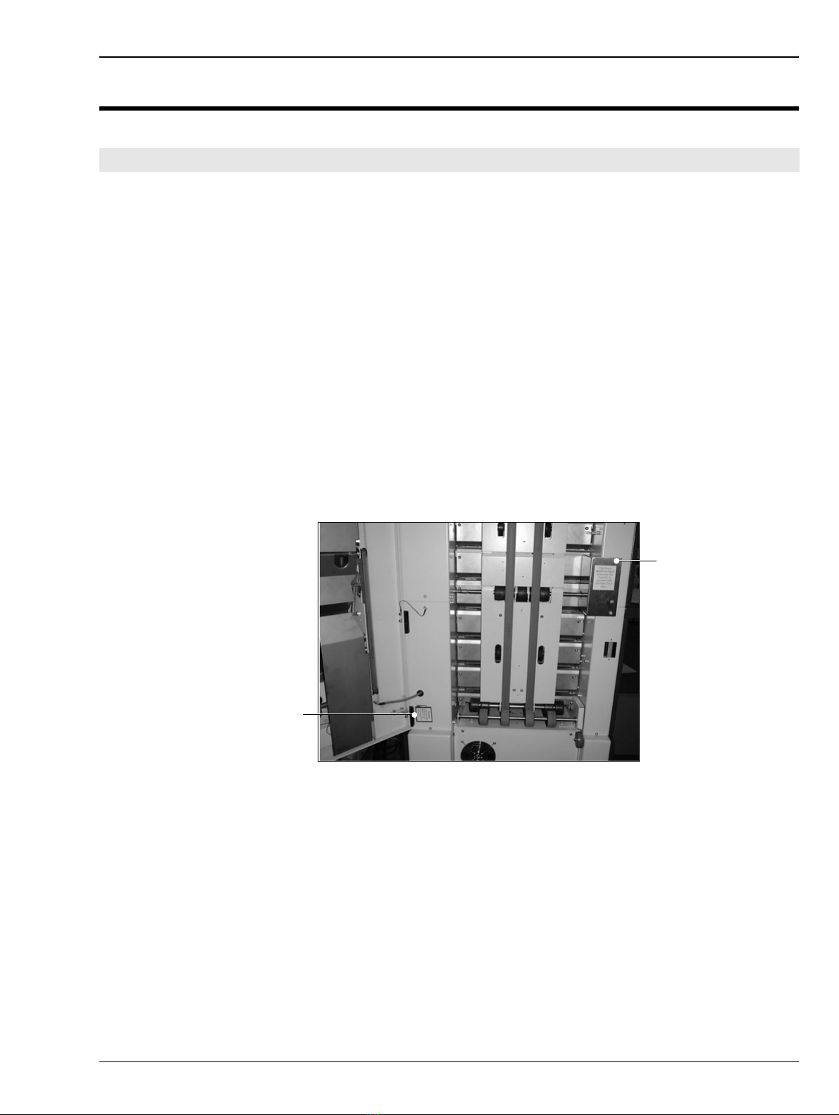
The following service aids are available and must be used where indicated:
950-042 DigiVAC Rear Door Gear Cover
If a service procedure requires the DigiVAC to be operated with the rear door
open, exposed gears are a hazard to the engineer. This gear cover MUST be
fitted.
950-043 DigiVAC Rear Door Safety Switch Bypass
If a service procedure requires the DigiVAC to be operated with the rear door
open, the safety switch on the door must be bypassed. Note: the gear cover
must also be fitted.
1.1.2 Operation
Operating instructions are included in the relevant Operating Manual. They
are not repeated here in this Service Manual.
1.1 Introduction
Rear Door
Gear Cover
Rear Door Safety
Switch Bypass

2Watkiss DigiVAC Service Manual - Issue 2 - 29/11/04
Overview • Introduction
1.1.3 Orientation
Where procedures refer to the R/H (right hand) or L/H (left hand) side of the
machine, this is always as viewed from the front, feed bin end of the machine.
Figure 1:1
1.1.4 Test Paper
Ensure that a supply of paper is available for testing purposes. This should ide-
ally be A4 and A3 (or 8½ x 11” and 11 x 17”). Check that the paper is cut
square and to the correct size before making any changes to the machine.
1.1.5 Metric and Imperial measurements
In most cases metric measurements and specifications are used in this manual.
A conversion chart is included in this manual (see Section 9.1). The DigiVAC
control panels can be set to use either metric or imperial measurements, refer
to the relevant operating manual.
1.1.6 Moving the DigiVAC
Over small distances, the DigiVAC can be moved by raising the jacking screw
and pushing it on its integral wheels. For longer distances, the DigiVAC is
supplied with transport wheels which should be used (see Section 7.2).
Figure 1:2
Front of the DigiVAC

Overview • Modules & Configuration
Watkiss DigiVAC Service Manual - Issue 2 - 29/11/04 3
Warning The DigiVAC is extremely heavy. Please observe good Health and Safety
practices when lifting or moving machinery.
The Watkiss DigiVAC Collator is a modular, vertical paper collating system,
built from a range of compatible modules. Two different versions are availa-
ble, the DigiVAC Standard and the DigiVAC+.
1.2.1 DigiVAC Standard
The DigiVAC Standard is available with 8 or 12 bins. It has a 5-digit counter
with total count and preset count.
Compatible accessories: X-Jogger, Straight Jogger, BookMaster range of
bookletmakers and trimmers.
1.2.2 DigiVAC+
The DigiVAC+ is available with 8 or 12 bins. Two towers can be linked
together (three towers at a future date). It has a Graphical User Interface (GUI)
comprising an 8.2" colour touch-screen, connecting cable and central process-
ing unit (CPU).
Compatible accessories: X-Jogger, Straight Jogger, BookMaster range of
bookletmakers and trimmers, Watkiss Automatic Stitch-Fold & Trim.
1.2.3 Modules
The illustration below shows the modules which make up a DigiVAC collating
system.
1.2 Modules & Configuration

4Watkiss DigiVAC Service Manual - Issue 2 - 29/11/04
Overview • Modules & Configuration
Figure 1:3
The table below lists the modules available for the DigiVAC Collator, some
of these are modules that may be used independently of the Watkiss DigiVAC
(e.g. BookMaster). The table gives the product abbreviation, the name, the fac-
tory part number and the module software address for each complete module
assembly.
Service information for ancillary equipment is provided in separate service
manuals:
• BookMaster Service Manual - part no. 969-240
• Automatic Stitch Fold & Trim - part no. 969-270
• SpineMaster Service Manual - part no. 969-230
Module Address: The module address is used by the system software to iden-
tify and control certain modules. The individual feed bins are identified by an
address number from 1 to 12, whilst the other modules use 17 upwards. Not
all modules need a module address.
Tower A Tower B
!
!
"#$
%
&
'
(
)
*
)
+
+Rear Door (DRDR or DNRD)
"Booklet Maker (DBMS, DBMP or DASF)
%Trimmer (DTMS, DTMP or DATR)
'Outfeed Conveyor (DBOC or DCNV)
!Tower B Top Module, including bridge
,(not illustrated) Straight Jogger
#Base Module (DBAS)
&First 4 Feeders (DF4F)
)Add-on 4 Feeders (DA4F)
*Control Panel (DCTL or DGUI)
(Top Module (DTOP)
$X-Jogger (DXJG)

Overview • Modules & Configuration
Watkiss DigiVAC Service Manual - Issue 2 - 29/11/04 5
CODE MODULE NAME PART NO. ADDRESS
DTOP DigiVAC Top Module 032-100
DTWB DigiVAC+ Tower B Top Module 032-101 21
DCTL DigiVAC Standard Control Panel 032-130
DGUI DigiVAC+ GUI Control Panel 032-131
DF4F DigiVAC First 4 Feeders 032-150 1/2/3/4
DA4F DigiVAC Add-on 4 Feeders 032-151 5/6/7/8 &
9/10/11/12
DigiVAC Add-On 4 Feeders
(incl Installation Kit, comprising conveyor and
rear door extensions)
032-152 5/6/7/8 &
9/10/11/12
DRDR DigiVAC Rear Door - to suit 8 bins 032-160
DigiVAC Rear Door extension to suit 12 bins 032-161
DNRD DigiVAC Rear Door, for connection to Nagel
BookletMaker 032-163
DigiVAC+, Tower B Rear Door to suit 8 bins 032-164
DigiVAC+, Tower B Rear Door extension to suit
12 bins 032-165
DBAS DigiVAC Base Module 200V, 50/(60)Hz
210V, 60Hz
230V, 50Hz
240V, 50Hz
032-200
032-201
032-203
032-204
17
DXJG DigiVAC X-Jogger 032-320
DigiVAC X-Jogger including Front Outfeed
Conveyor 032-321
DJGR DigiVAC Straight Jogger 110V
(Discontinued from July 2003) 115V
230V
032-322
032-323
032-324
AJGR Straight Stack Jogger, Adjustable 110V
Height (from July 2003) 115V
230V
050-050
050-051
050-052
DASF DigiVAC Automatic Stitch/Fold 115V
230V 041-533
041-534
DATR DigiVAC Automatic Trimmer 115V
230V 041-543
041-544
DCNV DigiVAC Stitch/Fold/Trim Outfeed Conveyor 041-524
DBMP DigiVAC BookMaster Pro incl. BCP
& Interface Kit 230V
115V 041-564
041-565
DTMP DigiVAC TrimMaster Pro 115V
230V 041-593
041-594
DBMS DigiVAC BookMaster Standard 100V
115V
230V
041-566
041-567
041-568
DTMS DigiVAC TrimMaster Standard 100V
115V
230V
041-584
041-585
041-586
BOC BookMaster Outfeed Conveyor 041-570
DASM DigiVAC Automatic SpineMaster 115V 60Hz
230V 50Hz 062-011
062-012 DASM

6Watkiss DigiVAC Service Manual - Issue 2 - 29/11/04
Overview • System Overview
The major elements of the DigiVAC modular collating system are shown
below.
Figure 1:4 The DigiVAC System
All systems comprise:
• Base Module
• Top Module
• Control Panel - GUI or Eco
• First 4 Feeders Module
• 1 or 2 x Add on 4 Feeders Module
Base Module: The Base Module houses the drive motor, vacuum and blow
pumps and associated electronics required for the DigiVAC’s operation. The
base also includes a toroidal transformer on all except 240V machines - see
Section 4.1.2 on 65 for details of transformer tappings.
The DigiVAC Base Module Rel.B was introduced at Serial No. 150 (Techni-
cal Bulletin 150 refers). The Rel.B base includes a 3-phase motor and
SMD8200 Inverter. The inverter takes a single-phase 50/60Hz 180-264V AC
electrical supply and inverts it to 230V AC 50Hz three-phase output for the
1.3 System Overview
SMD 8200 INVERTER
905-386 (S/N150+)
MOTOR DRIVE PCB
900-192 (S/N<150)
DRIVE
MOTOR
(S/N150+
3 PHASE)

Overview • System Overview
Watkiss DigiVAC Service Manual - Issue 2 - 29/11/04 7
Drive Motor. This ensures consistent revolution speed regardless of load
exerted on the machine and is essential for two-tower operation. Rel.B bases
require software V2.1a or later.
Top Module: The top module transports the collated sheets over the top drum
and down into the rear conveyor. In two tower configurations, Tower B has a
different top module which includes the connecting bridge.
DigiVAC Standard Control Panel: The DigiVAC Standard is fitted with a
touch membrane control panel which includes the display, control panel keys,
and speed control. In order to change the software of the DigiVAC Standard,
the Eprom must be changed.
DigiVAC+ Control Panel: The DigiVAC+ is fitted with a Graphical User
Interface (GUI). This consists of a Central Processing Unit (CPU) housed in
the Base Module, a link cable and a touch-screen. The CPU holds the boot
firmware and application software that controls the DigiVAC+ and the opera-
tion of the touch-screen.
System Power: Power enters the Base Module via the input fuses next to the
input connector, EMI filters and double pole isolation on/off switch. From
here it goes via the torroidal transformer (except on 240V machines) which
supplies the Interface PCB in the Base Module. The Interface PCB distributes
power throughout the machine.
Drive Motor: The drive motor turns the drive belts which in turn drive the
feed system in each bin. The feed timing is controlled by a clutch on the clutch
drive shaft of each bin. A tachometer located on the end of the drive motor
shaft provides the master timing signal for the whole system.
Communications: The Interface PCB is connected by separate power and
communications cables to each of the feed modules. Each 4-bin feeder module
has its own PCB. The feeder module PCB interprets instructions from the Con-
trol Panel. The feed bin PCB controls each bin clutch so that drive is engaged
at the exact moment and for the correct duration required.
Paper Sensors: Sensors on each bin provide feedback via the PCB to the
Interface PCB/Control Panel for the detection of double feed, miss feed and
empty bin conditions. A message is displayed on the control panel relating to
each condition.
System Air: The blower motor delivers air throughout the system for sheet
separation. Air passes to each bin through connected vertical pipes (sealed
with ‘O’ rings). The air blow in each bin can be controlled using the air taps
(see operating manual). The air blow is regulated by the 900-187 Air Blow
Control PCB.
The vacuum pump delivers vacuum throughout the system through connected
vertical pipes. Each feed bin has an individual valve and filter. The valve is
switched on and off by the main interface PCB. The vacuum pressure is fac-
tory set.
Paper Transport: Sheets are transported by dual conveyor belts upwards,
over a wide diameter drum at the top of the machine, and then down into jog-
ger or booklet-maker. Transporting the sheets upwards gives the paper a long,
straight path into the online finishing equipment.

8Watkiss DigiVAC Service Manual - Issue 2 - 29/11/04
Overview • Fuses
Paper Feeding: In each bin, the stack of paper is elevated on an air bed. The
bottom sheet of the stack is separated by means of air separation, and it is then
transported forwards by a vacuum conveyor. The sheet passes through a spe-
cially shaped gate and into the conveyor system. There are no operator adjust-
ments to the gate, the air blow, the vacuum or the tray height. The only
adjustment is to the profile of the vacuum conveyor.
Jogging: Two joggers are available for the DigiVAC. The X-Jogger stacks
and jogs sets either straight or with a 20° offset. It fits onto mounting pegs on
the front of the DigiVAC. The Straight Jogger is free standing, at either the
front or rear of the DigiVAC.
Note: To deliver sets to the front of the DigiVAC, the Front Outfeed Conveyor
must be fitted.
Multi Tower Systems: Multi-tower systems are only possible with the Digi-
VAC+. Two DigiVAC+ towers can be linked to give up to 24 bins. The top
module of Tower B includes connecting bridge which transports paper and
carries the communication between the two towers. The rear door on Tower B
is also different. The control panel is located on Tower A.
Figure 1:5
Fuses on the PCBs protect the motors and the voltage rails in the system.
Warning When changing a fuse, always ensure that the power is switched off and the
mains disconnected. Also ensure that the fuse holder grips the fuse firmly. A
loose fuse holder may cause connection problems. If needed, bend the tabs on
the holder to tighten the fit.
1.4 Fuses
LOCATION FUSE FUNCTION RATING
Mains input
socket - 12.5A Ceramic, Anti-surge, T
DigiVAC Base PCB F1 3.15A Glass, Anti-surge, T
F2 6.3A Glass, Anti-surge, T
DigiVAC Base
Power PCB F4 X-Jogger 2.0A Glass, Anti-surge, T
F5 Drive Motor 3.15A Glass, Anti-surge, T
X-Jogger PCB F1 X-Jogger 2.0A Glass, Anti-surge, T
Transformer Transformer 3.15A Ceramic, Anti-surge, T

Overview • Fuses
Watkiss DigiVAC Service Manual - Issue 2 - 29/11/04 9
FUSE SYMPTOMS OF FAILURE
DigiVAC Standard DigiVAC+
Mains input socket No mains switch illumination No mains switch illumination
Machine Dead Machine Dead
DigiVAC Base PCB F1 Control Panel Dead Control Panel Dead
Transformer LED on Transformer LED on
Machine Dead Machine Dead
DigiVAC Base PCB F2 Machine will start, but no
feed occurs showing up on
the bin as a Jam
‘PSU VOLTAGE ERROR: 28v’
message is displayed
No Jog or Oscillate Function
is available
DigiVAC Base Power
PCB F4 No Jog function ‘No Power to Stacker’ mes-
sage displayed
No Oscillate function selecta-
ble from the panel XJOG Mimic shows yellow
DigiVAC Base Power
PCB F5 Motor Stalled Error Motor Stalled Error
X-Jogger PCB F1 No Oscillate function ‘No Power to Stacker’ mes-
sage displayed
XJOG Mimic shows yellow
Transformer Mains switch is illuminated Mains switch is illuminated
LED on the transformer is
not illuminated LED on the transformer is
not illuminated
Machine Dead Machine Dead

10 Watkiss DigiVAC Service Manual - Issue 2 - 29/11/04
Overview • Fuses

Tools & Materials • Recommended Tools
Watkiss DigiVAC Service Manual - Issue 2 - 29/11/04 11
Chapter 2 Tools & Materials
It is recommended that Watkiss engineers carry the following tools and mate-
rials with them. Watkiss part numbers are included where relevant, although
many of the recommendations are standard tools which are readily available.
Some of the tools listed are not required directly for servicing the DigiVAC,
but are be required for DigiVAC accessories such as the Automatic Stitch-
Fold & Trim units and the BookMaster and TrimMaster range.
2.1 Recommended Tools
WATKISS
PART NO. DESCRIPTION
952-030 Screwdriver - POZI, No 3 - long
952-026 Screwdriver - Electrical + Neon
952-060 Spanner - Combination, 5.5mm
952-062 Spanner - Combination, 7mm (M4)
952-063 Spanner - Combination, 8mm (M5)
952-066 Spanner - Combination, 10mm (M6)
952-067 Spanner - Combination, 13mm (M8)
952-002 Special Tool - Spanner - single end, 17mm (M10)
952-003 Special Tool - Nut Spinner - short, 10mm (M6)
952-053 Pliers - Long Nose, small
952-056 Pliers - Side Cutters, small
952-043 Allen Key ‘L’ - 2.0mm
952-044 Allen Key ‘L’ - 2.5mm
952-045 Allen Key ‘L’ - 3.0mm
952-046 Allen Key ‘L’ - 4.0mm
952-047 Allen Key ‘L’ - 5.0mm
952-093 Handled Allen Key - 2.0mm
952-092 Handled Allen Key - 2.5mm
952-091 Handled Allen Key - 3.0mm
952-090 Handled Allen Key - 4.0mm
Ball Ended Allen Key - 1.5mm
952-096 Ball Ended Handled Allen Key - 3.0mm
952-006 Knife - Scalpel Handle
952-007 Knife - Scalpel Blade (10A)
952-004 6” Rule
952-193 M5 Tap
Tap Wrench
3,4,5mm Pin Punches
952-404 3/4LB Ball Pein Hammer
955-001 7mm AF Nut Runner

12 Watkiss DigiVAC Service Manual - Issue 2 - 29/11/04
Tools & Materials • Consumables
2.2 Consumables
WATKISS
PART NO. DESCRIPTION
Lint Free Cloth
951-007 Loctite 242 (thread locking compound)
951-023 Loctite Retainer 641 (weak retaining compound)
Light Oil (SA30/40)
2.3 Service Aids
WATKISS
PART NO. DESCRIPTION
Digital Multi Meter
370-052 Bin Sensor Calibration Stock
950-041 Tray Gauge - 2 off
950-042 Rear Door Gear Cover
950-043 Safety Switch Bypass
950-044 Blow Gauge
950-045 Vacuum Gauge

Service Procedures • General Service Procedures
Watkiss DigiVAC Service Manual - Issue 2 - 29/11/04 13
Chapter 3 Service Procedures
Service Aids for Safety
The following service aids are available and must be used where indicated:
950-042 DigiVAC Rear Door Gear Cover
If a service procedure requires the DigiVAC to be operated with the rear door
open, exposed gears are a hazard to the engineer. This gear cover MUST be
fitted.
950-043 DigiVAC Rear Door Safety Switch Bypass
If a service procedure requires the DigiVAC to be operated with the rear door
open, the safety switch on the door must be bypassed. Note: the gear cover
must also be fitted.
3.1.1 Bin Test Mode
For some service procedures, it is necessary or helpful to put individual bin
modules, into test mode. This allows some functions to be tested without using
whole-machine communications including:
• Detector function
• Tray empty sensor function
• Clutch function
• Valve function
• Feed drive belt tension
Procedure
1. Switch off the DigiVAC at the mains ON/OFF switch.
2. Press and hold one of the bin ON/OFF switches on the relevant module
whilst switching the mains power back on. The bin module is now in Test
Mode.
Tip: To put all bin modules into Test Mode, press one of the bin ON/OFF
switches on each bin module whilst switching on the power.
3.1 General Service Procedures
Rear Door
Gear Cover
Rear Door Safety
Switch Bypass
14 Watkiss DigiVAC Service Manual - Issue 2 - 29/11/04
Service Procedures • General Service Procedures
3.1.2 Removing the Rear Conveyor Assembly
For many service procedures it is necessary to remove the rear conveyor
assembly.
Procedure
1. Push conveyor to the left against the spring pressure
2. Pull the right edge of the conveyor outwards
3. Ease the conveyor assembly downwards and lift it clear of the collator
Figure 3:1 Removing the rear conveyor assembly
After refitting the rear conveyor, make sure all the conveyor belts are correctly
aligned.
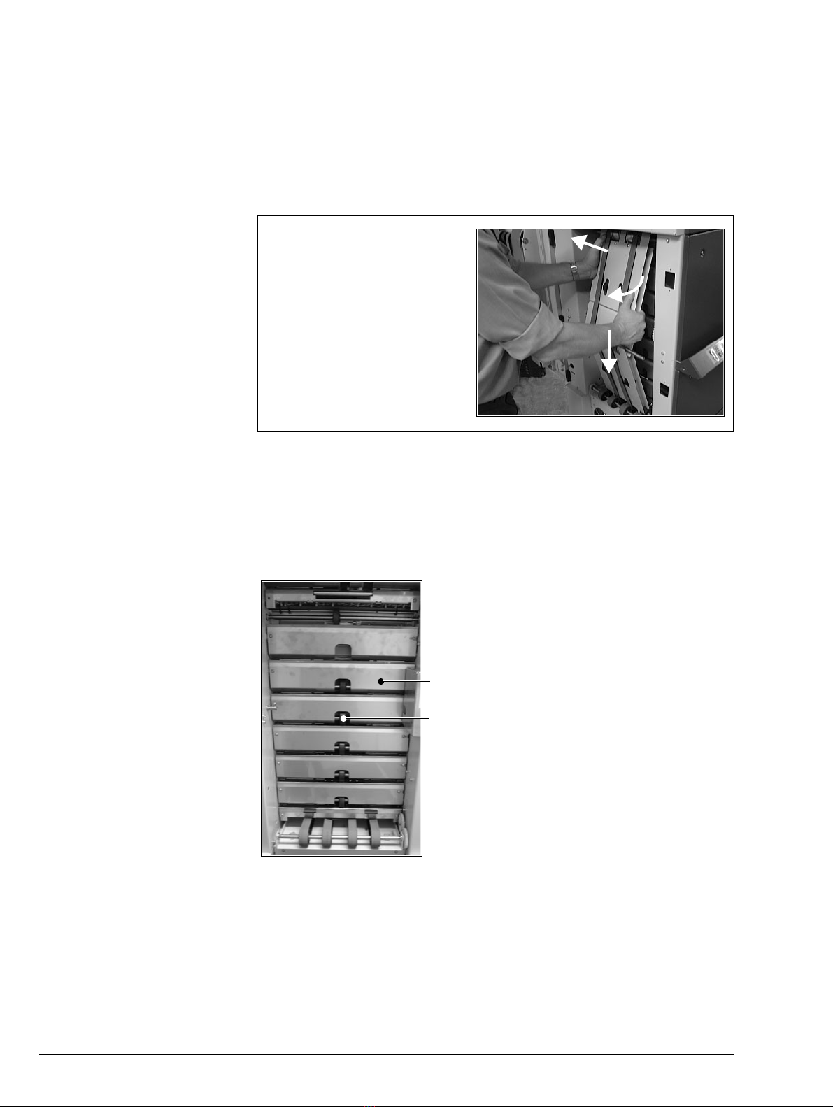
3.1.3 Removing the Rear Deflector Plates
For many service procedures it is necessary to remove the rear deflector plates.
Figure 3:2 Rear Deflector Plates
There are two possible methods of removing a rear deflector plate:
• Remove both M5 button head screws and lift the plate clear.
• Remove the M5 button head screw on the R/H side of the machine (this
is the left hand screw when viewed from the rear of the machine). Then
loosen the L/H screw and the plate can be eased out.
1
2
3
1. Push conveyor to the left against
the spring pressure
2. Pull the right edge of the con-
veyor outwards
3. Ease the conveyor assembly
downwards and lift it clear of the
collator
Deflector Plates
Conveyor Wheels
Table of contents
Other Watkiss Industrial Equipment manuals


