Schwing FW 18 User manual

Service Manual
Remote Control Cable/Radio
553
Radio Control FW 18
Table of Contents
Black-and-white control / proportional control
(as from series 1987)
1. SAFETY AND ACCIDENT PREVENTION
REGULATIONS
2. SHORT INSTRUCTIONS
3. PREFACE
4. EXTRACT FROM THE TERMS OF
WARRANTY
5. MODEL PLATES
6. TECHNICAL DATA
7. SHORT DESCRIPTION
8. CONTROL AND MONITORING EQUIPMENT
9. COMMISSIONING
10. OPERATING THE RADIO CONTROL
11. PUTTING OUT OF OPERATION -
CHANGEOVER
12. SAFETY DEVICES AND TROUBLESHOOTING
13. MAINTENANCE WORKS AND CHECKS,
14. CHANGING AND CHARGING OF BATTERY
1. Safety and Accident
Prevention Regulations
The safety and accident prevention regulations
stipulated in the operating instructions for the
truck-mounted concrete pump are applicable and
binding for the operation with the remote control
too.
•To avoid any unintended working movement of
the machine and before changing from one control
system to another:
!SET ALL CONTROL ELEMENTS IN THE
DRIVER’S CAB AND ON THE REMOTE
CONTROL PANEL TO ZERO POSITION.
STOP DRIVING ENGINE.
•Only specialists are allowed to repair the radio
controls.
• In case of any failure, notify the SCHWING
after-sales service.
• Only persons authorized by Messrs.
SCHWING are allowed to open leaded housings.
• Unauthorized manipulations may result in
great damages and render all warranty claims void.
See also section 4.1.
ATTENTION! Before welding the machine, make
absolutely sure that the plugs of the connection
cables are detached from sockets 7, 8, and 9 of the
receiver. Protect the socket by means of a sealing
cap. Non-observance would result in damage to
the electronic control system (see also customer
information K 29).
89
7
5
4
Home
PrintPrint

Service Manual
Remote Control Cable/Radio
554
Safety Regulations - Concrete Pumps with
placing booms
READ OPERATION MANUAL FOR THE
MACHINE. It describes the safe, proper, and most
efficient way to operate. KNOW YOUR
MACHINE!
When operating the concrete pumps
and placing booms, the safety regula-
tions of the responsible employers’ lia-
bility insurance company have to be
observed. The observation of these reg-
ulations shall be the responsibility of
the contractor and operator.
The following are some supplementary recom-
mendations:
• All safety devices and provisions against acci-
dents, such as warning labels and information
signs, coverings, etc., must be in place. Do not
remove or tamper with them. If they are miss-
ing, replace them.
See the following drawings for location of labels:
KVM 23 - 309903 KVM 32 - 309779
KVM 25 - 309918 KVM 36 - 309780
KVM 28 - 309778 KVM 42 - 309855
KVM 31 - 309878 KVM 52 - 309930
•Check the operational reliability of the
machine each time before it is put into operation.
Any defects found must be repaired immediately.
• Allow the machine to be operated and main-
tained by qualified personnel only.
• Make use of handles and steps when ascending
or descending.
• Keep steps, platforms, control and monitoring
devices, etc. free of dirt, oil, snow, and ice.
• Before leaving the machine, protect it from
unauthorized use and unintentional movements.
• Unauthorized presence in the immediate area
of the concrete pump and placing boom is not
allowed. Warn persons who are in the immediate
area. Stop work if persons do not leave the area
after having been warned.
• Wear personal protective equipment when
operating the machine.
Traveling
•Drive on bridges, decks, etc. only if the bearing
& height capacity is adequate.
• The vehicle must not travel with an unfolded
boom.
• When traveling, the shut-off valves of the out-
rigger cylinders must be shut, and the outrigger
must be locked by means of the transport safety
devices.
Jacking
•Prior to jacking, check soil conditions. If nec-
essary, increase the support foot area by placing
square timbers underneath.
• Keep sufficient distance from excavations;
slopes could break away because of support pres-
sures.
• On inclines, place chocks behind the wheels,
release the break, let the vehicle run against the
chocks, and apply the brake again; then jack.
• After jacking, close the shut-off valves of the
outrigger cylinders, otherwise the cylinders will
lose oil, and the machine could sink to one side.
Concrete Pump
•In order to avoid concrete splashes due to suc-
tion of air, the agitator hopper must always be
filled with concrete up to the mixing shaft.
• DO NOT OPERATE THE CONCRETE
PUMPS WITHOUT THE HOPPER GRILL
FIRMLY BOLTED DOWN.
• NEVER ALLOW HANDS NEAR THE
GATE, VALVE, OR AGITATOR HOPPER
WHILE THE MACHINE IS RUNNING.
• Before the gate or valve housing is opened,
stop the driving motor. If this is not possible (e.g.
in the case of cleaning work), the remote control
cable has to be disconnected to avoid unintentional
movement of the valve. The concrete pump opera-
tor must make sure that no unauthorized person is
present in the area of the open gate or valve hous-
ing or starts the concrete pump accidently.
Placing Boom
•The placing boom may be operated only up to
a maximum wind speed of 48 m.p.h. (77 km/h =
wind force 8).
Home
PrintPrint

Service Manual
Remote Control Cable/Radio
555
•Under all circumstances, keep the boom suffi-
ciently away from obstacles such as boom cranes,
scaffolds, buildings, etc.
• The placing boom must never be used as a
crane for lifting materials.
• The length of the end hose must not exceed 4
meters (13 feet) in length. The end hose should not
be kinked during pumping operations. The safety
cable between the boom pipeline and the end hose
must be in place and attached.
• If end hose is replaced with a combination of
reducers and hoses (for example, a 5-4 reducer and
4” hose), then all hoses, reducers, etc. must be fas-
tened with safety cables and may not exceed the
weight of the recommended end hose. Any of the
above mentioned items should be capable of han-
dling the pumping pressures of the specific equip-
ment.
• Perform regular maintenance and lubrication
of boom at 1 year prescribed intervals and do a
complete check of the boom and tower annually
using Schwing America’s “Regular Check-Up
Concrete Placing Booms” form, SAE-510. This
form is supplied with all units and is available from
Schwing America.
Pipelines
•PIPELINE AND CLAMPS MUST BE SUFFI-
CIENT FOR PUMP CAPABILITY.
• The pipeline connections must not be opened
under working pressure. Before the pipeline is
opened, pressure must be relieved by sucking back
the concrete. Secure couplings after assembly of
the pipeline.
• Because of the increased danger of accidents,
the following important points must be adhered to
when blowing out the pipeline with compressed
air:
a. Blowing-out should be performed under the
supervision of an expert.
b. No pipe bends or hoses should be connected to
the end of the pipeline during the blow-out
process.
c. No person is allowed to be next to the concrete
discharge end.
d. A catch basket must be fitted to the concrete
outlet.
e. The concrete outlet should be positioned high
enough to permit easy discharge of the con-
crete.
f. The pipe cleaning head must be equipped with
a working gauge and a properly sized air regu-
lator hand valve.
g. The plug must be long enough to ensure air
tight sealing of the pipeline at the catch basket
after the pipeline has been blown out.
h. The plug must be tight-fitting to prevent com-
pressed air from flowing around the plug and
into the concrete.
i. Work at the pipeline is allowed only after the
pipeline has been relieved of compressed air.
Ensure that the air pressure has been com-
pletely relieved.
j. Single pipe sections and short pipes up to a
length of 40 feet must not be blown out. Great
danger of accidents exists because of rapid
expulsion due to too little mass!
• When laying pipeline, use as few bends as pos-
sible. Horizontal pipelines must be adequately sup-
ported. When installing a vertical pipeline, the best
method is to use upright struts supporting the low-
est vertical pipe. Each succeeding pipe should then
be anchored to the building.
• It is preferable to install pipelines within build-
ings whenever possible. See operator’s manual and
“Pumping Concrete” booklets for more informa-
tion on pipeline installation.
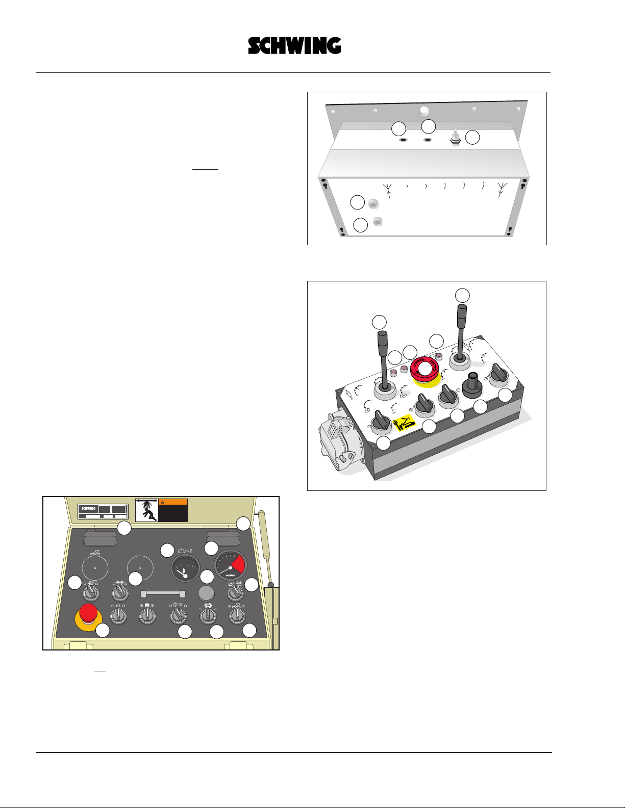
Remote Controls
•To avoid unintended operating movements of
the machine, set all control levers or switches in
the operator’s cabin and on the remote control
panel to the neutral position prior to any switch-
over to local or remote control and prior to discon-
nection of the remote control line.
Electrical Connections on the site-
Hydraulic Power Packs, etc.
•The power supply connection for electrically
driven stationary concrete pumps or the electric
power packs for pumps or booms has to be
arranged by the contractor.
• The power supply on construction sites,
according to VDE 0100 paragraph 55, may be
taken only from a special feed point, e. g. an elec-
trical distribution box with current-operated
Home
PrintPrint

Service Manual
Remote Control Cable/Radio
556
ground protection. The connection of the power
supply cable to the feed point may be carried out
only by a qualified electrician.
• Fuse protection and conductor size are the
responsibility of the electrician and must comply
with the National Electrical Code and any local
codes.
2. Short Instructions
NOTE: These short instructions are to be regarded
as a memory aid only and do not dispense from the
full knowledge of the complete operating instruc-
tions.
Preparing the Commissioning
•Switch all controls on the machine and on the
transmitter to “0” and “off.”
• Switch truck engine off when warm.
• Check whether the cables are connected to the
antenna, power supply, receiver control, and
machine control panel.
Making Ready for Operation
• Switch ignition “on.”
• Place charged rechargeable battery into the
transmitter and the spare battery into the charger.
NOTE! Place battery into charger with poles in the
correct position.
•Set selector switch on machine control panel to
“Remote Control.”
• Unlock all EMERGENCY OFF buttons on the
machine.
• Switch on receiver. LED indicates: RED.
• Unlock EMERGENCY OFF button of trans-
mitter.
• Switch on transmitter power supply (selector
switch to “ON”). LED on receiver lights up
GREEN.
• If there is no reason for a fault, every further
control command will be passed on by receiver to
the machine pilot control.
Operating Mode
• Start truck engine.
• The transmission and reception of a valid con-
trol command is indicated on the transmitter and
receiver by the green LEDs flashing.
• If no command is sent within a period of 20
seconds, the transmitter reverts to “idle state.” The
LED of the receiver indicates permanently GREEN
= READY. The “idle state” is cancelled by operat-
ing any switch.
IMPORTANT:
•Comply with safety and accident prevention
regulations.
• Consider maximum range of transmitter.
• Avoid radio shadows.
• Switch the transmitter off by turning the selec-
tor switch to “OFF.” All machine functions are
immediately interrupted when the EMERGENCY
OFF button is pressed.
Reasons for Automatic Switch-off
• Interference by external transmitters
• Insufficient range due to radio shadows
• Empty battery
• Transmitter controls are not switched to “0” or
“OFF” when switching on the receiver.
3. Preface
The operating instructions contain important infor-
mation concerning the operation and maintenance
of your
SCHWING MACHINE.
A copy thereof should always be within easy reach
of the machine operator and the members of the
maintenance crew. Any handling of the machine
implies knowledge and close observation of the
operating instructions. It is advisable, therefore,
especially prior to commissioning, to read the
instructions carefully several times and to become
familiar with the machine.
NOTE: Perfect operation and maintenance ensure
lasting operational reliability.
Downtimes as the result of avoidable maintenance
work can largely be avoided if particular attention
is given to the following points:
Home
PrintPrint

Service Manual
Remote Control Cable/Radio
557
•Always operate the machine gently and with-
out force!
• Never change of your own values set or speci-
fied by the manufacturer, such as hydraulic oil
pressures, tightening torques, etc.!
• Carry out all the prescribed maintenance and
inspection work completely and punctually!
• Use only lubricants and operating supplies
according to our recommendations!
• During operation, regularly read all the built-in
monitoring instruments and note any unusual reac-
tions (noises, lack of power, etc.)!
• Install only ORIGINAL SCHWING SPARES!
During operation and maintenance work, the rele-
vant safety regulations must be strictly observed.
(Note the extract from the terms of warranty.)
In the event of failure, possible queries, and for
ordering spare parts, please contact:
Schwing America, Inc.
5900 Centerville Road
White Bear, MN 55110
(651) 429-0999
TWX: 910-563-3539
Subsidiary of: Friedrich Wilh. Schwing GmbH
or the authorized representative for your area.
Always quote the machine model, the serial num-
ber, and the information on the model plates.
Carry out operation and maintenance of the chas-
sis and the engine installed according to the
maker’s instructions.
4. Extract from the Terms of
Warranty
The following extract from the terms of warranty
deals with those damages which may result from
incorrect operation and maintenance:
The warranty does not extend
a. to defects arising in consequences of natural
wear and tear, inadequate installation and erec-
tion work by third parties, inadequate commis-
sioning, inadequate or negligent handling,
subjection to unsuitable stresses and loadings;
b. to defects caused by modifications or repair
work carried out by the purchaser or by third
parties without our prior approval.
c. to defects arising due to the installation of
spare parts which are not genuine SCHWING
parts.
If a defective machine continues to be used in spite
of the defect, the warranty shall be confined only
to the original defect.
**Complete terms of warranty, see section 7 of the
General Trading Terms.
When exporting our machines, special regulations
possibly in force in the destination country must
be complied with.
*Any export of SCHWING machines without
authorization from SCHWING is not allowed.
Appropriate Applications
The machine is assigned exclusively to the appli-
cation purposes mentioned in these operating
instructions.
The company of Schwing will not be liable for
damages, if
•the machine is used for operations which are
not the normal practice.
• the operation instructions, the safety regula-
tions, and the accident prevention regulations are
not observed.
Home
PrintPrint

Service Manual
Remote Control Cable/Radio
558
5. Model Plates
A model plate is attached to both the transmitter
and the receiver.
Radio remote control can only be performed with
equipment which have identical characteristics on
their model plates.
Operation of the radio remote control is without
charge in the FRG according to PTT approval
AGB-242.
Please note here:
Model: ______________________
Equipment Number: ______________________
Frequency: _____________________
of your remote control equipment, and always
quote them in case of queries, etc.
6.Technical Data
Proportional control
Transmitter:
Operating Frequency : in the 70 cm band
(27.55 inches)
RF output power : 4 mW
Control channels : 18 black-and-white
and 8 proportional
Operating voltage and
power requirements : 9,6 V DC 70 mA
Type of operation : portable hand
transmitter
Transmission range : approximately 50
m (164.5 feet)
Transmission of the
control functions : digital
Charging unit for
transmitter battery : installed in the
receiver
Receiver:
Operating frequency : in the 70 cm band
(27.55 inches)
Telegram evaluation : by microcomputer
Operating voltage : 11.5 to 14.5 V or
23 to 28 V, 200 mA
Relay outputs : 18
Analogous outputs : 8 in sequence + 6,
12, 18, V for 24 V
or : 8 in sequence = 3,
6, 9 V for 12 V
7. Brief Description
The new generation of SCHWING RADIO
REMOTE CONTROLS are an advanced develop-
ment of the systems first introduced in 1983.
Radio remote controls can be retrofitted or fitted at
the factory.
Dependent on the machine model, black-and-
white or proportional controls are available.
Transmitter
The transmitter is powered by a rechargeable
nickel-cadmium battery. An inbuilt “idle state cir-
cuit” ensures optimized utilization of the battery
charge. The “idle state circuit” switches the power
supply off when no switch is operated within a
period greater than 20 seconds. The power supply
switches on again when a switch is operated. The
operating voltage is permanently monitored.
Home
PrintPrint

Service Manual
Remote Control Cable/Radio
559
An LED indicates to the machine operator that the
battery needs to be changed. If the battery is not
changed in approximately 30 minutes, the moni-
toring circuit blocks the transmitter.
The “coding electronics” converts every switch
operation into an unmistakable transmit signal
which is combined with a special identification
code before being sent by the transmitter.
As is known from the cable remote control system,
the boom speed with PROPORTIONAL CON-
TROL is dependent on the excursion of the control
lever:
Short excursion = low speed
Long excursion = high speed
By a precise graduation of the ranges of adjust-
ment, the speed is almost continuously variable.
With the respective actuation of the control levers,
several movements can be made simultaneously.
Receiver
The receiver is mounted in the driver’s cabin and is
powered by the truck voltage. The hydraulic com-
ponent (pilot control) is connected by cable to the
machine control panel via the socket provided.
NOTE: ONLY connect the receiver of the PRO-
PORTIONAL CONTROL to 24 V on-board volt-
ages with negative pole connected to the chassis
(negative to ground). The BLACK-AND-WHITE
CONTROL receiver can be connected to 24 V on-
board voltages with negative to ground or, AFTER
SPECIFIC READJUSTMENTS, to 12 V systems,
or AT ZERO POTENTIAL to systems with posi-
tive to ground.
NOTE! INCORRECT VOLTAGE, SHORT-CIR-
CUIT, AND OVERLOAD destroy the electronics.
For warranty reasons, we advise against installing
the system by yourself.
The “radio telegram” emitted by the transmitter is
detected and monitored by the receiver. If the
receiver electronics recognizes the “radio tele-
gram” as correct and complete, the signal is sent to
the connected machine pilot control.
The transmitter and receiver are precisely tuned to
each other. An external transmitter cannot affect
operation because different information (e.g.
equipment no.) belongs to the contents of each
radio telegram, and this is checked by the receiver.
In the event of an electronic fault or loss of tele-
gram, the previous functions initiated are stopped.
The two-colour LED indicates the state of the
receiver electronics: “FAULT”, “READY”,
“OPERATING.” A storage rack incorporating the
recharge electronics for one transmitter battery is
mounted in the receiver housing.
Home
PrintPrint

Service Manual
Remote Control Cable/Radio
560
8. Control and Monitoring
Equipment
Radio Remote
Figure 1 = Black-and-white transmitter
Figure 2 = Proportional transmitter
1 - Control lever with spring-centered 0-position
for placing boom functions
2 - see 1
3 - EMERGENCY OFF button
4 - Potentiometer: output adjustment of concrete
pump
5 - Antenna socket with removable antenna
6*- Selector switch: vibrator on/off
7*- Button: horn on truck
8 - LED: EMERGENCY OFF button operated
9 - Selector switch: truck engine speed adjustment
10*- Selector switch: engine on/off
11- Selector switch: concrete pump (pumping - off
- reverse)
12- LED: battery charge monitor
13- LED: radio signal output monitor
14- Selector switch: transmitter power supply ON/
OFF
* = Optional extra
8
9
14
13
12
10
11
4
3
2
18
914
13
12
10 11
46
4
52
1
Home
PrintPrint

Service Manual
Remote Control Cable/Radio
561
Receiver
1 - Toggle Switch: receiver ON/OFF
2*- 0.4 A fuse (receiver power supply)
3*- 1.6 A fuse (charger power supply)
4 - Two -colour LED: receiver state
GREEN = receiver READY
GREEN, flashing = receiver OPERATING
RED = receiver FAULT
5 - Two-colour LED: Battery charge control
GREEN = battery CORRECTLY inserted
(pole), charging
RED = battery INCORRECTLY inserted
(pole), replace correctly (turn) immediately
OFF = no battery inserted
6 - Plug-in module: transmitter battery charger
7 - Socket for connecting cable to machine control
panel
8 - Antenna socket
9 - Socket: power supply for receiver and charger
* = Not included in the new radio remote control
series
5
4
321
89
7
6
5
4
Home
PrintPrint

Service Manual
Remote Control Cable/Radio
562
9. Commissioning
Preparations
1. Switch all controls on the machine and on the
transmitter to “0” or “OFF.”
2. Switch truck engine off when warm and with PTO
switched on.
NOTE: After a “remote start”, the engine should
run smoothly immediately. The remote control can
give no cold start assistance.
3. Disconnect remote control cable from control
panel and replace with cable: receiver - control
panel.
4. Check whether power supply cable, antenna cable,
and connecting cable are connected to the receiver.
5. Check whether antennas for transmitter and
receiver are mounted. If not, install.
Ready for operation
1. Switch on “ignition”.
2. Insert charged battery into the transmitter and
spare battery into charger.
NOTE! Make sure that the charger is inserted with
the correct polarity
3. Set selector switch on machine control panel to
“remote control”.
4. Unlock all EMERGENCY OFF buttons on the
machine by turning them to the right.
5. Switch on the receiver using the toggle switch.
LED lights up: RED. The receiver is waiting for a
control signal.
6. Unlock EMERGENCY OFF button of transmitter
by turning to the right.
7. Set selection switch to “ON”. This causes the
following:
a) The power supply of the transmitter is
switched on. The red LED lights up for a short
time and extinguishes if the battery volt-
age is correct. The rhythmical flashing of the LED
indicates that a radio telegram is being
transmitted.
b) The receiver is switched to “READY”.
The display of the two-colour LED changes to
GREEN.
If the two-colour LED continues to indi-
cate “RED”, the receiver is at FAULT.
NOTE: The fault may be caused by an
external transmitter in the immediate vicinity.
The equipment is ready for operation.
O I O I
S
T
O
P
E
M
E
R
G
E
N
C
Y
0
5
10
15 20
25
30
35
U/minx100
Do not operate at
pressures exceeding
the rating of the
entire material
delivery system.
WARNING
D
O
N
O
T
O
P
E
R
A
T
E
I
N
R
E
D
Z
O
N
E
!
20 100
60 80
40
°
C
O I O I AUTOMATIKHAND
89
7
6
5
4
13
10 15
14
11
5
4
321
8
9
14
13
12
10
11
4
3
2
1
Home
PrintPrint

Service Manual
Remote Control Cable/Radio
563
10. Operating the Radio Remote
Control
NOTE! In order to avoid undesired movements of
the machine, ALWAYS switch off the power sup-
ply of the transmitter (selector switch to “OFF”)
when the machine is not in use.
If the engine is not fitted with an engine ON/OFF
switch, start the engine with the “ignition key”.
Putting on the transmitter
1. Insert the spring hooks of the upper belts into the
carrying frame.
2. Place the belts over the shoulders.
3. Insert the spring hooks of the lower belts into the
carrying frame.
4. Adjust the length of the upper belts as required by
means of the buckles.
*If desired, the carrying belt can be completely
removed from the transmitter.
Transmitter mode
1. When the receiver is ON, unlock the
EMERGENCY OFF button of the transmitter by
turning to the right, and set the selector which to
“ON”.
2. If an engine ON/OFF switch is fitted, start the
truck engine using the selector switch.
3. If no control switch is operated when the
transmitter power supply is switched on, the
transmitter first sends “address telegrams” without
a control command. The LEDs flash “GREEN”.
After 20 seconds the “idle state circuit” switches
the transmitter power supply off. The LED
extinguishes. The receiver remains in the
“READY” state and the LED remains permanently
8
9
14
13
12
10
11
4
3
2
1
8
914
13
12
10 11
46
4
52
1
Home
PrintPrint

Service Manual
Remote Control Cable/Radio
564
“GREEN”. After operating any switch, the power
supply of the transmitter returns. Work may then
proceed.
Operation of the machine by wireless remote con-
trol is identical to that for cable remote control.
Please observe the following instructions for safe,
uninterrupted operation:
Capacity of the transmitter battery
The capacity of each battery is dependent upon:
• the age of the battery,
• the charge level, and
• the ambient temperature.
Under extreme conditions, the capacity of the
transmitter battery may be exhausted after about 8
hours of service. (System will be shut down by the
undervoltage.)
In order to ensure uninterrupted operation, we rec-
ommend always having a charged battery on hand
while charging another battery.
The integrated charge electronics prevents an over-
load.
NOTE: In order to prevent unnecessary reduction
of NiCd battery lifetime, we recommend that the
batteries be regularly changed after every 3-4
operating hours BEFORE the voltage monitor
indicates a battery change by flashing.
Transmitter range
For safety reasons, the transmitter range is limited
but is sufficient for all conceivable construction
site situations. If the transmitter is taken out of this
broadcast range, all of the machine’s functions
will be stopped automatically.
Radio shadows
The machine operator must select his location in
such a way that he has unrestricted visibility into
the machine’s working area and that there is no
hindrance to the radio traffic.
The following may be taken as a rule of thumb:
The location has been chosen correctly if, at a
maximum distance of 50 meters (164.5 feet), the
machine and the receiver’s antenna can be seen
without restrictions.
Breaks in the work
In order to prevent unauthorized operation of the
machine, the operator should not set down the
transmitter once it has been switched on.
IMPORTANT! Before removing the transmitter,
switch off the truck engine and press the EMER-
GENCY OFF button. Set the selector switch to
“OFF” and lock the transmitter into the driver’s
cabin. Secure the machine against unauthorized
5
4
321
8
9
14
13
12
10
11
4
3
2
1
Home
PrintPrint

Service Manual
Remote Control Cable/Radio
565
use (see operating instructions of truck-mounted
concrete pump).
Turn the receiver off by means of the toggle
switch.
Putting out of Operation
1. Set all controls on the transmitter to “0” or “OFF”
position.
2. Set the selector switch to “OFF”.
3. Press the EMERGENCY OFF button.
4. Switch off the receiver by means of the toggle
switch.
5. **The LED extinguishes.
6. Switch the truck engine off and remove the
“ignition key”.
7. Lock the transmitter in the driver’s cabin and
secure the machine against unauthorized use.
Changeover to Cable Remote Control
1. Put out of operation as described above.
2. Remove the connecting cable: between receiver
and control panel from machine control panel.
3. Connect standard remote control cable to the
machine control panel.
4. Perform commissioning as normal for cable
remote control.
5
4
321
8
9
14
13
12
10
11
4
3
2
1
5
4
321
Home
PrintPrint

Service Manual
Remote Control Cable/Radio
566
12. Safety Facilities
In addition to manual switch-off (EMERGENCY
OFF button), the radio remote control is provided
with automatic facilities to immediately interrupt
or inhibit work operations in the event of a radio
fault.
1. SAFETY TEST DURING COMMISSIONING
After switch-on, the receiver first tests whether its
radio channels are free and undisturbed.
If a signal is received, the receiver immediately
returns to the state: FAULT.
NOTE: After reception of a VALID signal, the
receiver reverts to the state: READY.
2. SAFETY CHECK DURING OPERATION
The operational status will be suspended by:
• switching the system off manually.
• actuating one of the EMERGENCY OFF but-
tons.
• undervoltage of the transmitter battery.
The undervoltage monitor will shut down the
transmitter if battery voltage falls below the
safety threshold. Work may proceed after exchang-
ing the battery.
• receipt of an invalid “telegram”
Transmission of the control commands from the
transmitter to the receiver is effected
using “telegrams”. These telegrams consist of a
so-called basic code (“address telegram”)
in addition to the actual control command. It is on
the basis of this basic code that the
receiver recognizes the “voice of its transmitter”.
Invalid telegrams may be caused, for example, by:
• interference due to external transmitters
• radio shadows
• contradictory control commands
IMPORTANT! Should you note during operation
that the machine does not execute any control
commands:
•press the EMERGENCY OFF button and
switch off the transmitter power supply.
• Set all controls of the transmitter to “0” or
“OFF” position.
• Change location (the transmitter may be in a
radio shadow).
• Unlock the EMERGENCY OFF buttons by
turning them to the right, and switch on the
• ransmitter power supply.
The equipment is ready for operation again.
Fuses
(not included in new series)
Sockets to receive two fuses are built into the
upper part of the receiver.
0.4 A = receiver
1.6 A = charger
Home
PrintPrint

Service Manual
Remote Control Cable/Radio
567
13. Maintenance Works and
Checks
The radio control is virtually maintenance-free. To
insure uninterrupted operation, observe the follow-
ing instructions:
IMPORTANT!
1. The entire system is resistant to splashed water, but
it is not waterproof.
2. Keep all components clean and dry and use the
cover caps to close off immediately any connection
plugs which are not being used.
Changing the transmitter battery
1. Switch off the transmitter and press the
EMERGENCY OFF button.
2. Undo the locking screws by rotating through 90
degrees.
3. Remove battery.
4. Insert charged battery with its contacts first into the
battery compartment. The position of the positive
and negative poles is not important due to the
automatic polarity switch-over circuit.
5. Replace cover. Turn the locking screws 90 degrees
and clip in by applying a slight pressure. DO NOT
screw in.
NOTE: Check that the cover is correctly mounted.
If mounted upside down, there is a visible gap
through which humidity can penetrate into the bat-
tery compartment.
Charging the transmitter battery
The battery in the charger is exchanged in the
same way as described above, but:
CAUTION! The charger is not equipped with an
automatic polarity switch-over circuit. If the LED
lights up RED, IMMEDIATELY remove the bat-
tery and change over the contact position (turn the
battery around). The LED will indicate GREEN if
the polarity is correct.
NOTE! The time it takes to charge a battery com-
pletely is approximately 14 hours or less, if the
battery is exchanged in good time.
NOTE! DO NOT USE any other chargers: RISK
OF EXPLOSION.
NOTE! Only use ORIGINAL SCHWING NiCd
rechargeable batteries: There is a RISK OF DAM-
AGE to the equipment if incorrect rechargeable
batteries are used.
NOTE! Do not open the batteries (fumes hazard-
ous to health).
NOTE! Do not throw away batteries that are dead
or defective. Instead, dispose of them at an
approved collection point, which is equipped to
deal with special wastes.
Home
PrintPrint

Service Manual
Remote Control Cable/Radio
568
Home
PrintPrint

Service Manual
Remote Control Cable/Radio
569
Radio Control FW 20
Table of Contents
1. TABLE OF CONENTS
2. SHORT OPERATING INSTRUCTIONS
3. FOREWORD
4. DESIGNATED USE, WARRANTY
5. SAFETY REGULATIONS AND ACCIDENT
PREVENTION REGULATIONS
6. CERTIFICATE OF APPROVAL
7. SHORT DESCRIPTION
8. TECHINCAL DATA, RATING PLATES
9. MONITORING-, WARNING-, AND CONTROL
ELEMENTS
10. PRE-OPERATING INSTRUCTIONS
11. OPERATION
12. EMERGENCY SHUT-OFF
13. INTERRUPTIONS OF WORK, END OF
OPERATION
14. REPLACING OF BATTERY
15. MALFUNCTIONS
16. MAINTENANCE, REPLACING OF FUSES
17. REPAIR
Copyrighted. These operating instructions must not be
duplicated, used improperly, or communicated to third
parties without our consent - not even by way of
excerpts.
Home
PrintPrint

Service Manual
Remote Control Cable/Radio
570
2. Short Operating Instructions
The short operating instructions are to be used as a
short reference only. They are by no means a
replacement for the detailed operating instructions.
Please observe also the operating instructions of the
machine!
Preparations
• Set up the machine.
• Set all control elements on the machine and the
transmitter to their “0” position.
• Shut off the vehicle engine as long as it is still
warm, and leave the ignition on.
• Plug in the receiver cable.
• Set the operating mode selector switch on the
machine to “REMOTE”.
• Set the power supply switch of the electric
control to “ON”.
• Unlock all EMERGENCY SHUT-OFF buttons
of the machine.
Ready-for-Operation State
•Switch on power supply of transmitter; LED 4
is flashing.
• Push EMERGENCY SHUT-OFF 1; LED 4 is
flashing faster.
• Pull EMERGENCY SHUT-OFF 1; LEDs 2and 4
are extinguished; LED 3 is permanently lit: empty
messages are being transmitted.
•Actuate control element; LED 3 is flashing: instruc-
tion messages are being transmitted.
Emergency Shut-Off
Pushing in the EMERGENCY SHUT-OFF BUTTON
interrupts the main functions of the machine.
Automatic Shut-Off
for example, in case of:
• low battery voltage
• message errors
• electronic module failure
• no command instruction messages received
(for more than 30 minutes).
Interruptions of Work
• Bring placing boom into transport position.
• Set control elements to “0”-position.
• Shut-off power supply of transmitter
• Set power supply switch of the electric control
to “OFF”.
• Lock away transmitter.
23456
1
Home
PrintPrint

Service Manual
Remote Control Cable/Radio
571
3. Foreward
The present operating instructions are addressed to all
persons in charge of operating and servicing the
SCHWING RADIO REMOTE-CONTROL UNIT
described overleaf and to owners or users of the
equipment.
The operating instructions are to help you familiarize
yourself with the equipment in order to
• use it for the purposes for which it has been
designed,
• operate the equipment safely in order to avoid
dangers, and
• use it properly and efficiently in order to save
costs.
The equipment has been built in accordance with state-
of-the-art standards and the recognized safety rules.
Nevertheless, the equipment may constitute a risk to
persons and property if it is incorrectly used, operated,
serviced, or repaired.
Using the equipment presupposes the perfect
knowledge and strict observance of the operating
instructions. Therefore, you should read the operating
instructions carefully and repeatedly in order to
familiarize yourself with the equipment before putting
it into operation for the first time. Reading the
instructions after the work has begun is too late!
In addition to the operating instructions, the generally
applicable legal and other mandatory accident
prevention rules in the country of use are to be
observed.
In the event of failures, possible queries, and for
ordering spare parts, please contact:
Schwing America, Inc.
5900 Centerville Road
White Bear, MN 55127
(651) 429-0999
TWX: 910-563-3539
or the authorized representative for your area, quoting
always the machine model, the serial number, and the
information on the model plates.
Carrying out operation and maintenance of the chassis
and the engine installed according to the maker’s
instructions.
4. Designated Use
The equipment is exclusively designed for the control
of certain types of SCHWING machines.
Any other use is considered as contrary to its
designated use. The equipment must be used in
accordance with the operating instructions.
In addition to these, the operating instructions of the
machine must also be observed.
The equipment may only be installed by persons
entrusted with such work by SCHWING.
The designated use also includes the observance of the
operating, servicing, and repair instructions prescribed
by the manufacturer:
• SCHWING radio remote control units must be
installed, removed, operated, and repaired only by
specially trained and qualified personnel. Unautho-
rized additions and modifications are not permit-
ted.
• For servicing purposes only, ORIGINAL
SCHWING SPARE PARTS are to be used.
• Before export, the equipment must be adapted
by the manufacturer to the regulations in force in
the country of use.
Non Designated Use
The manufacturer cannot be held liable for damage of
the equipment resulting from use outside its designated
use and from incorrect and inappropriate operation and
maintenance.
Home
PrintPrint

Service Manual
Remote Control Cable/Radio
572
Extract from Terms of Warranty
The conditions mentioned below are an extract from
the terms of warranty relating particularly to damage
which may be caused by incorrect operation and
maintenance.
The warranty does not include:
a) defects due to natural wear, inappropriate
installation and fitting by third parties, incorrect
commissioning, incorrect or negligent treatment and
inappropriate use;
b) defects caused by modifications or repair work
performed by the customer or by third parties without
our previous approval;
c) defects caused by the installation of non-original
SCHWING spare parts.
If defective machinery/equipment is kept in use in spite
of defects, the warranty only includes the original
defect.
For the complete terms of warranty, please refer to our
“General Conditions of Sale”.
Home
PrintPrint
This manual suits for next models
2
Table of contents
Other Schwing Remote Control manuals