SCI WLS430 Series User manual

WLS430 Series
Load Weighing System
Basic Installation, Calibration and
Operating Instructions
SCI-CL2000 Installation Calibration & Operating Instructions V0.1

Compuload CL2000 Series Load Weighing System Manual
WWW.SCALEANDCONTROL.COM A
Important Safety Information
Precautionary Statements
Warning–Indicates a potentially hazardous situation which, if not avoided, could lead to
serious injury or death.
Caution–Indicates a potentially hazardous situation which, if not avoided, could lead to a
mild to moderate injury.
Information –Indicates important points that Operators and Installers need to fully
understand.
Refer to Documentation –Indicates important points which must be obtained by
referring to manufacturers Service, Operation, or Maintenance Manuals.
It is your sole responsibility to install, operate, and maintain the SCI system in a manner that will
not cause damage to persons, property, or anything else. Always use safe practices and adhere
to any laws that may be in place.
Do not install, operate, or maintain the SCI system unless you are completely competent and
understand the system and equipment it is mounted on.
Read this manual completely prior to use and familiarize yourself with the components
and locations.

WLS430 Series Load Weighing System Manual
WWW.SCALEANDCONTROL.COM 1
Table of Contents
Important Safety Information ..................................................................................................A
Table of Contents..................................................................................................................... 1
1. Introduction....................................................................................................................... 2
1.1. Components............................................................................................................... 2
2. Installation Procedure for the WLS430............................................................................ 3
2.1. Fitting the Display to the Operators Cabin............................................................... 3
2.2. Installing the Pressure Transducer .......................................................................... 3
2.3. Wiring the WLS430 to the Forklift or Loader............................................................ 3
2.4. Establishing a Weighing Point.................................................................................. 4
3. Basic Calibration Instructions ......................................................................................... 5
4. Basic Weighing................................................................................................................. 6
Settings Page........................................................................................................................... 9
Appendix A –Hydraulics........................................................................................................10

WLS430 Series Load Weighing System Manual
WWW.SCALEANDCONTROL.COM 2
1. Introduction
The WLS430 Weighing Indicator is IP67 rated digital indicator designed for use on forklifts and
small wheel loaders in temperatures between -22F –158F degrees.
Operating Voltage is 8-32 Volts DC.
The WLS430 will generally be installed with a hydraulic pressure transducer mounted in the piston /
ram side of the lift circuit cylinder. The hydraulic transducer should be mounted in an area that is
not affected by high pressure cleaning. DO NOT SPRAY HARDWARE WITH PRESSURE
WASHERS.
1.1. Components Standard Components
Figure 1
1. RAM Mount
2. Hydraulic Adapter –Customer Specified
3. Display
4. Wire Harness
5. Pressure Transducer
3
1
5
2
4

WLS430 Series Load Weighing System Manual
WWW.SCALEANDCONTROL.COM 3
2. Installation Procedure for the WLS430
WARNING: These basic installation instructions are given based on the installer having
previous experience in the servicing and maintenance of machinery. General safety
precautions should be undertaken similar to carrying out maintenance on this type of
machinery. Inexperienced personnel should not undertake this task if they are unsure of
the safety precautions necessary.
2.1. Fitting the Display to the Operators Cabin
Select a suitable location and using the mounting bracket, mount the display. Both a suction
mount and bolt on brackets are provided. Allow plenty of room for the cable at the rear of the
display. A minimum of 3”should be provided between the display and any surface for adequate
cable routing and connector removal.
DO NOT DRILL OR WELD ONTO ANY PORTION OF A R.O.P.S. or F.O.P.S.
A bracket, however, can be bolted onto a lock striker plate, window frame aperture or turret
support. Consider wiring and cabling when choosing a mounting position. Consideration should
also be given so the instrument does not impede operator vision. Vibration should also be taken
into account so as not to damage the hardware.
2.2. Installing the Pressure Transducer
PRECAUTIONS
1. Lower Boom completely to the ground and stop the engine.
2. Operate the tilt, and lift levers to ensure no residual pressure is present in the hydraulic
system. Refer to Owner’s Manual to relieve pressure.
3. Remove the hydraulic tank filler cap to remove any pressure from the oil reservoir tank.
4. Slightly loosen any “easy to get at” fitting in the piston side of the lifting circuit to ensure
no pressure is present. The transducer is to be fitted into the lifting circuit of the hydraulic
system between the control valve and the lifting cylinders. See Appendix A for hydraulic
information. Connect appropriate adapter to allow transducer to be mounted in a safe
position. Avoid areas that are subject to oil and water. Do not run cable through
articulated or moving areas of the machine. Tighten the fittings. Start the engine and lift
the forklift boom carriage approx. ½” from the ground. Bleed the air from the line, then
using spanners, retighten the transducer.
2.3. Wiring the WLS430 to the Forklift or Loader
The WLS430 fits machines that have 8-32Vdc power supply. Voltages other than this may
require a voltage converter.
RED = Power –This is constant supply voltage and keeps the clock running.
YELLOW = Switched supply. Can be tied to Ignition/Accessory or its own circuit to turn the
system on.
BLACK = Ground

WLS430 Series Load Weighing System Manual
WWW.SCALEANDCONTROL.COM 4
2.4. Establishing a Weighing Point
The WLS430 is a static scale. Because it uses hydraulic pressure from the lift cylinders to
determine weight, a fixed point must be selected for accurate results. Recording weights from
positions other than this fixed point, will provide inaccurate results. The weighing point on a
standard forklift is usually about 3 feet above the ground. For a wheel loader, it is when the
loader arms are approx. horizontal. Other positions can be selected, but that position must be
used when weighing.
The weighing point is identified by either:
A. Applying stickers to the mast or loader arms (stickers usually supplied in kit).
B. Welding a pointer to the mast or loader arms identifying the position.
C. Mark the loader arm pivot points so you align two paint marks.
When getting to the weighing point, it is preferred to have the last motion be in a
downward direction to the weighing point. This motion will ensure the rod side pressure
is eliminated and will not affect the weight values. For best results, slowly approach the
position in an upward direction and overshoot slightly. Then slowly lower the boom until
the weighing point is reached.

WLS430 Series Load Weighing System Manual
WWW.SCALEANDCONTROL.COM 5
3. Basic Calibration Instructions
The calibration instructions below are given based on a typical installation.
This system can be used in a large variety of applications, and changing the parameters that
are set will greatly affect the performance of this scale.
NOTE- Ensure you press OK to save any changes prior to pressing ESC to ensure changes are
saved.
1. Ensure you have an accurate test weight of approx. 1/3 –½ of the machine capacity. The
more accurate the test weight, the more accurate the scale. The test weight must fill the
bucket like the material you will be weighing. Any protrusion of the test weight past the
buckets cutting edge will greatly reduce accuracy.
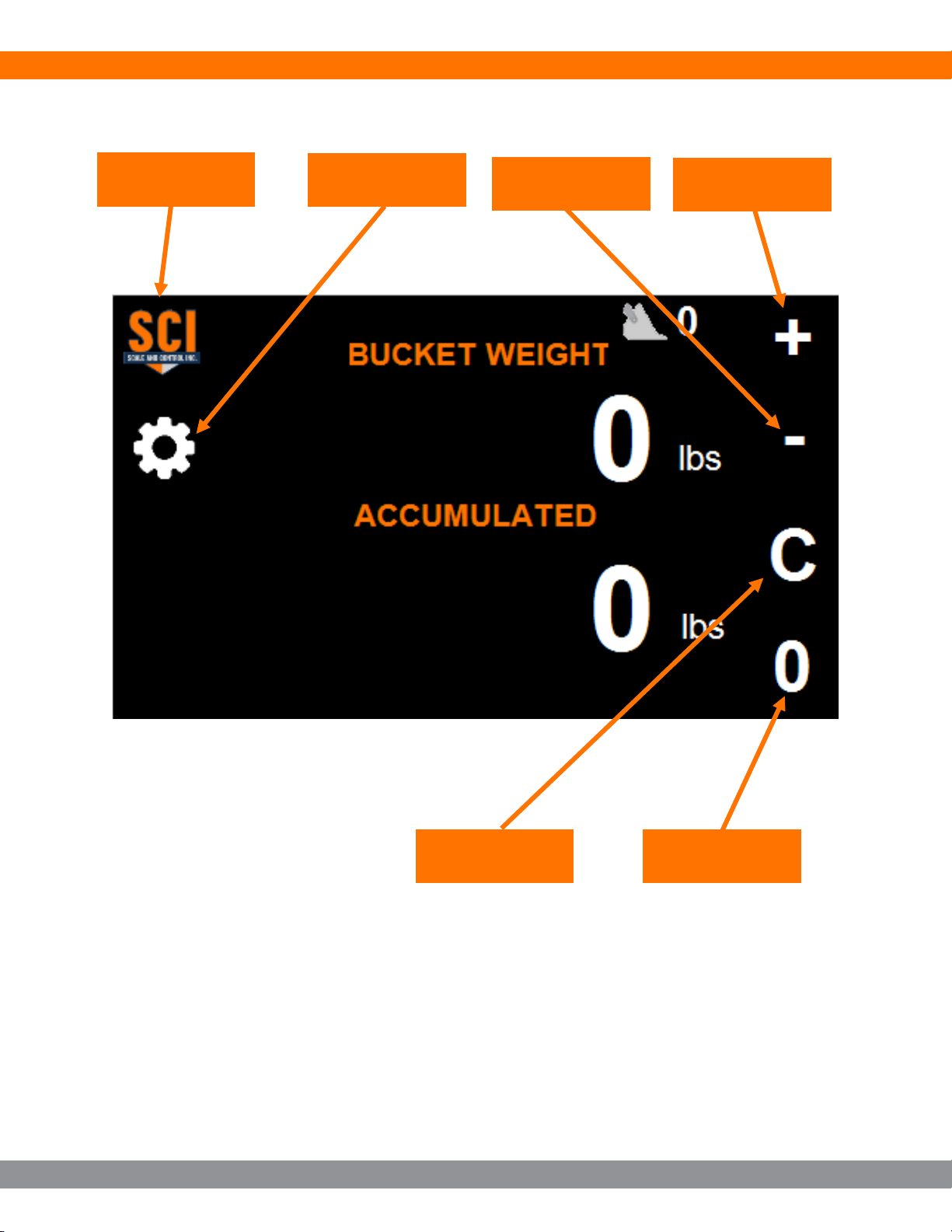
2. Start the forklift or loader, and the WLS430 should also turn on. The indicator should
power up and go through a short power up cycle. Once the power up cycle finishes, the
indicator will show a random reading. To ensure you have the hydraulic pressure
transducer fitted correctly, raising of the forks or bucket should result in the figure on the
screen rising.
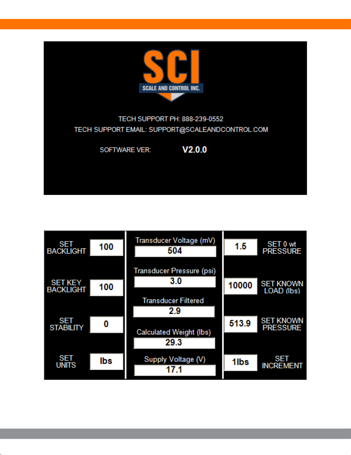
3. Press the settings button (GEAR) on the top left-hand corner of the screen to enter the
settings page (Figure 5).
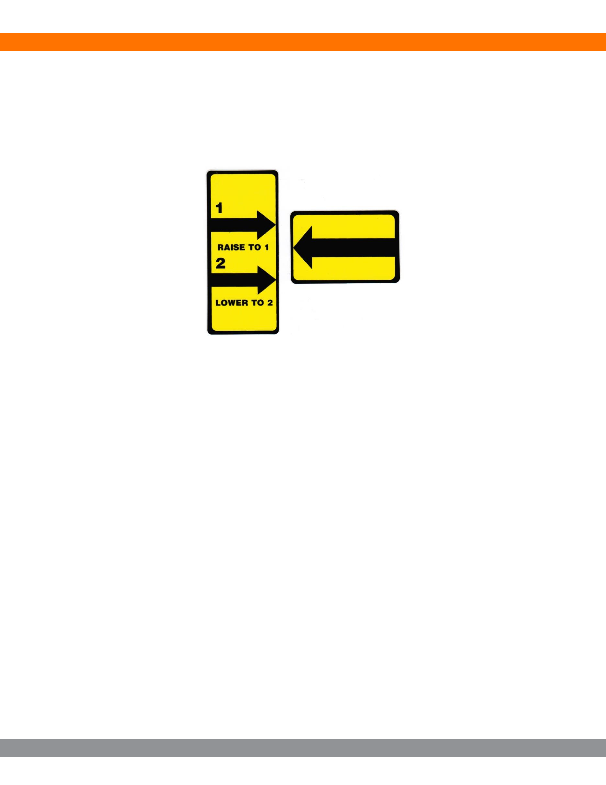
4. Raise the empty Forks or Bucket to your weighing height. (Raise to 1, Lower to 2, Optional
Decal) Allow approx. 2-3 seconds for the weight to settle, Press “Set 0wt Pressure” on the
screen to set the Zero Weight Calibration Pressure.
5. Lower boom and place your test weight onto the forks or bucket. Do not lift to weighing
height at this stage. Enter the test weight amount to “Set Known Load (lbs)”by pressing
the button on the right side adjacent to the field. Enter the known weight in lbs using the
directional keys at the bottom of the display. Press OK to save and then press ESC to
exit.
6. It is now time to pick up the test weight and raise to the weighing height, (Raise to 1,
Lower to 2, Optional Decal). Allow approx. 2-3 seconds for the weight to settle, and then
press the “Set Known Pressure” key once.
7. Exit the settings page and check the “Displayed Weight” value to see if the weight displays
the test weight amount. If not, you may need to repeat the calibration process.
8. Validate a lighter known load reads correctly. If correct, calibration is complete.
Perform as many test weighing until you are satisfied the system is working correctly.
If at any time the indicator indicates an error message during the calibration process, call tech
support for assistance. Before calling check that the hydraulics have been installed into the
correct ‘Piston / Ram’ circuit of the machine, and also check that your test weight is at least 1/3 -
½ machine capacity.

WLS430 Series Load Weighing System Manual
WWW.SCALEANDCONTROL.COM 6
4. Basic Weighing
NOTE 1: All reference to weighing position refers to raising the forks or bucket up to a pre-
determined position and lowering slightly and slowly.
The pre-determined position is determined by the installer and is generally indicated by stickers
on the mast (Raise to 1, Lower to 2) and on the carriage.
(Arrow)
Figure 2
1. With the forks empty and mast vertical, raise forks up to the weighing position.
2. If other than 0.00 (zero) is displayed press ZERO key
3. Apply the load and raise up to the weighing position. The weight will vary as the load is
raised and then lowered, but should stabilize after 2-3 seconds.
4. To Accumulate the weight once the weight has been obtained, Push the + Key (upper
right-hand corner) once. The Bucket Count and the Accumulated weight will be
displayed. Repeat Step 3 to accumulate further buckets.
5. To CLEAR the TOTAL, press the “C”button (bottom right-hand corner) The TOTAL and
Bucket Count will return to zero to allow the next Load to be completed.
6. NOTE: - Pushing the “-“button will delete the last bucket weight only.

WLS430 Series Load Weighing System Manual
WWW.SCALEANDCONTROL.COM 7
Figure 3
Clear
Accumulate
Zero
Settings
Info
Delete Last

WLS430 Series Load Weighing System Manual
WWW.SCALEANDCONTROL.COM 8
Figure 4
Figure 5

WLS430 Series Load Weighing System Manual
WWW.SCALEANDCONTROL.COM 9
Settings Page
The Settings Page is accessed by pressing the gear symbol on the Home Page. Below is a list
of parameters that can be changed. Refer to Figure 5.
“Set Backlight”–press the button to adjust the display backlight level. Each press will increase
the brightness until 100 is reached, then it will cycle back to 10.
:Set Key Backlight”- press the button to adjust the button backlight level. Each press will
increase the brightness until 100 is reached, then it will cycle back to 10.
“Set Stability”–This is a filtering constant. Increasing the setting will smooth the displayed
weight value, however, it comes with increased weighing time to settle.
“Set Units”–4 units are available. LBS, KGS, TON, and MTON. 1 TON is equal to 2000lbs. 1
MTON is equal to 1000kg. 1kg is 2.206lbs.
“Set 0 wt Pressure”–Press to set the empty bucket pressure. Hold to manually adjust the
value.
“Set Known Load (lbs)”- Press to set the known load amount.
“Set Known Pressure”–Press to set the pressure of a known loaded bucket. Hold to manually
adjust the value.
“Set Increment”–Press to change the displayed increment value. Available options include
1lbs, 2lbs, 5lbs, 10lbs, 25lbs, 50lbs, 100lbs, 250lbs, 500lbs.

WLS430 Series Load Weighing System Manual
WWW.SCALEANDCONTROL.COM 10
Appendix A –Hydraulics
Adapter Size Identification Chart
Size
JIC
Thread
JIC
Wrench
ORS
Thread
ORS
Wrench
Pipe
Thread
Pipe
Wrench
ORB
Thread
ORB
Wrench
-04
7/16-20
9/16
9/16-18
11/16
1/4-18
11/16
7/16-20
9/16
-06
9/16-18
11/16
11/16-16
13/16
3/8-18
7/8
9/16-18
11/16
-08
3/4-16
7/8
13/16-16
15/16
1/2-14
1
3/4-16
7/8
-10
7/8-14
1
1-14
1 1/4
7/8-14
1
-12
1 1/16-12
1 1/4
1 3/16-12
1 3/8
3/4-14
1 1/4
1 1/16-12
1 1/4
-16
1 5/16-12
1 1/2
1 7/16-12
1 5/8
1-11 1/2
1 1/2
1 5/16-12
1 1/2
-20
1 5/8-12
2
1 11/16-12
1 7/8
1 1/4-11 1/2
1 7/8
1 5/8-12
2
Proper tightening techniques
Using proper tightening techniques is important to keep the environment clean and prevent
costly repairs and maintenance on hydraulic equipment. Here, http://blog.parker.com/turn-vs-
torque-how-making-the-right-choice-keeps-your-hydraulic-fitting-connections-leak-free, you will
find valuable information on proper installation and tightening of adapters. Here,
http://blog.parker.com/10-things-not-to-do-when-your-hydraulic-fitting-leaks, is additional
information on how to prevent leaks.
Key points for working on hydraulic systems
1. Do not use Teflon Tape on hydraulic systems. The tape can break free and move
through the system and get caught in valve spools and pumps causing damage.
2. Use two wrenches when tightening adapters and hoses. One wrench holds the hose or
adapter and the other tightens the nut.
3. LOTO –Lock Out Tag Out. Hydraulic systems are dangerous to work on and proper
training should be obtained before maintaining or modifying any connections.
Preventing someone from operating while working on the system is imperative.
4. Hydraulic fluid under pressure can kill. Know what you are doing and read the
manufacturer’s manuals completely.

WLS430 Series Load Weighing System Manual
WWW.SCALEANDCONTROL.COM 11
Flange, JIC, flat face O-ring

WLS430 Series Load Weighing System Manual
WWW.SCALEANDCONTROL.COM 12
BSPP Chart
DIN Chart

WLS430 Series Load Weighing System Manual
WWW.SCALEANDCONTROL.COM 13
NOTES
Table of contents
Other SCI Accessories manuals
Popular Accessories manuals by other brands

Vinotemp
Vinotemp Element EL-BWC108-SS owner's manual

SmartPlug
SmartPlug BM30 installation instructions

NeuLog
NeuLog NUL-212 Guide

RIDGID
RIDGID R8700 Series Operator's manual

Nobile
Nobile Plug BT Mounting and operation instructions

S+S Regeltechnik
S+S Regeltechnik Aerasgard RC02-Modbus Operating Instructions, Mounting & Installation