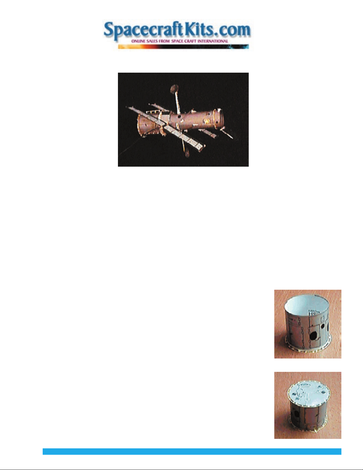
2. ASSEMBLE THE TELESCOPE TUBE.
HST’s Telescope Tube is actually two parts: the Optical Telescope Assembly is a precision-
engineered truss which holds the secondary mirror in exactly the right position. Forward of this
is a shade called the Forward Light Shield which protects the optics from stray light.
Select Parts Sheet D from the kit. Find the words OPTICAL TELESCOPE ASSEMBLY and FORWARD
LIGHT SHIELD along one end of the silver side. Smear a small amount of glue, using a glue stick,
along the whole end, covering the wording, and making the glue-smear exactly 1/2 (13mm) inch
wide (measure first, and mark with pencil). The glue must cover all the way out to the edge.
Bring the opposite edge around, forming a tube with the silver side out. Overlap exactly the measured
and marked 1/2 inch (13mm) onto the glue. (If it overlaps less than 1/2 inch, other parts will not fit.)
Adjust so that the overlap is straight. Press and hold the surfaces together until the glue sets. Insert a
wooden ruler through the tube to press the seam against. Impart a curve to the seam to match the
tube’s curve. Be careful not to crease the tube anywhere, keeping it as evenly round as possible.
Set your previously assembled AFT SHROUD down with the PRIMARY MIRROR
ASSEMBLY facing up.
Set the TELESCOPE TUBE down, centered on the PRIMARY MIRROR ASSEMBLY so that the
seam is on the side across from the keel fitting. SCI’s address should be at the bottom. Adjust
the tube so that the Keel fitting, marked with an arrow, is centered below and between the two
black circles on the tube. To be precise, the printed arrow should align midway between the letters P.O in SCI’s address at
the base of the tube.
(The silver circle representing HST’s Primary Mirror may not be exactly centered... sorry, this was due to a manufacturing
error, which you can read more about if you want.) Apply glue to hold them together, and let dry.
Anyway, make sure the TELESCOPE TUBE is centered atop the AFT SHROUD, even if the silver circle is not.
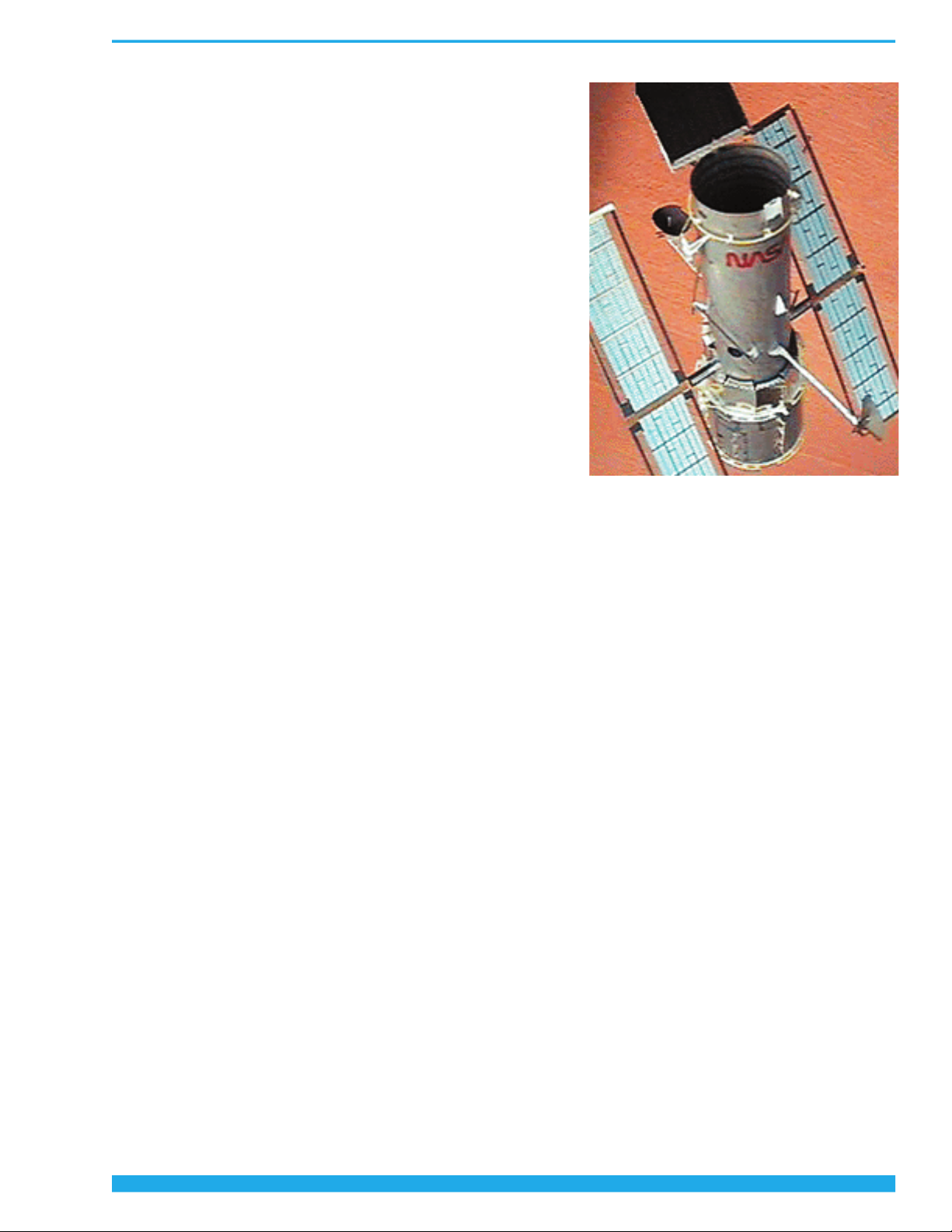
3. INSTALL THE SECONDARY MIRROR.
HST’s Secondary Mirror is held in exact position (within 0.0025mm) by graphite-epoxy
trusses in HST’s Optical Telescope Assembly. In HST’s Cassegrain optical system, the
Secondary receives light gathered and reflected from the hyperbolic Primary Mirror. The
Secondary’s own precise curvature reflects and focuses the light down through the hole in
the Primary, into the cameras and other scientific instruments in the Aft Shroud.
From parts sheet B release the two halves of the SPIDER. Place them together slot into slot
as shown, but turned at right angles to each other, to form a + when viewed from above. Secure with glue and let dry.
From sheet A, release the small, circular, silver SECONDARY mirror. Place it silver side up onto the cross beams below the
arrow in the illustration above. The edge of the mirror will snap into four small notches as it comes in contact with the
crossbeam. It will be a tight fit, causing the SPIDER to deform slightly. Secure with a droplet of glue at each notch.
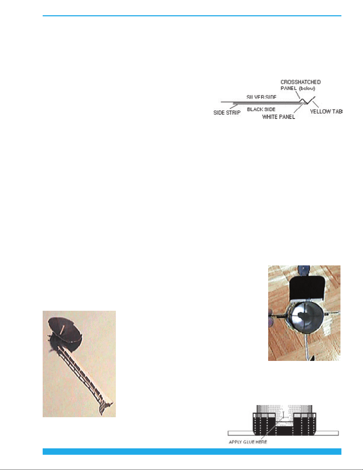
From sheet A, release the BAFFLE. Wrap it around a pencil, curling it so its hashmarked end will be overlapped. Smear
some glue over the hashmarked end. Wrap the other end around and overlap it so that
the hashmarks are covered. This will create a cone-shape. Press the surfaces together,
using a pencil inside, till the glue sets.
Set the completed BAFFLE narrow end down, onto the silver SECONDARY MIRROR
inside the SPIDER, as shown below. Secure with glue.
Out at the ends of each of the four SPIDER legs there are 3 prongs. Bend the middle
prong slightly one way, and the other two slightly the other way, on all 4 legs.
Place the SPIDER inside the TELESCOPE TUBE with the silver SECONDARY MIRROR
pointing aft toward the PRIMARY MIRROR. Adjust the bends in the SPIDER’s prongs so
that they brush against the inside of the tube enough to hold it in place.
Work the SPIDER into the TELESCOPE TUBE with long-nose pliers, so that its top is
2-1/2 inches (65mm) down from the end of the tube. It will meet the truss printed
inside. Turn the SPIDER so that one leg points in the same direction as the keel fitting.
Secure with glue.
2
Hubble Space Telescope Assembly Instructions