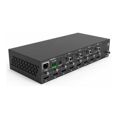
Scion-Tech PRO-6000B Series User manual

PRO-6000B Series Operating Manual
Issue 1.1V –17/06/2008 - 1 - Scion Tech Ltd - 1 - - 1 -
Scion-Tech Ltd
Operating Instructions
PRO-6000B
CAT5 Television Distribution System
Table of Contents
Product and Contents ---------------------------------- 2
Important Information and Safety ------------------- 3
Connecting Media Devices --------------------------- 4
Connecting Receivers---------------------------------- 7
Software-------------------------------------------------- 8
Changing Default Inputs ------------------------------ 12
Specifications ------------------------------------------- 13
Troubleshooting and Support------------------------- 14

PRO-6000B Series Operating Manual
Issue 1.1V –17/06/2008 - 2 - Scion Tech Ltd - 2 - - 2 -
Product and Contents
Included accessories
No.
Accessory Item
Qty
1
PRO-6000B CAT5 Television Distribution Hub
1
2
PRO-0202 12V 2.5amp Mains Adapter
1
3
PRO-0209 Single IR Blink Emitter
1
4
PRO-0203 RS232 Interface Cable
1
5
CD-ROM Server Software )
1
1 2 3
45

PRO-6000B Series Operating Manual
Issue 1.1V –17/06/2008 - 3 - Scion Tech Ltd - 3 - - 3 -
Important Information
Environment
Do not use this product near water.
This product should be kept away
from heat sources such as radiators,
cookers etc. It should also not be
placed in rooms where the
temperature is less than 5°C or
greater than 40°C.
The AC adaptor is used as the main
disconnect device. Ensure that the
AC outlet is installed near the unit
and is easily accessible.
Warning
To prevent the risk of electrical
shock, do not expose this product to
rain or any other type of moisture.
Unplug this unit from power if it
emits smoke, an abnormal smell or
makes unusual noise. These
conditions can cause fire or electric
shock. Confirm that smoke has
stopped and contact an authorised
service centre.
Information on Disposal for Users of
Waste Electrical & Electronic
Equipment
Private households
This symbol on the products and/or
accompanying documents means that
used electrical and electronic products
should not be mixed with general
household waste.
For proper treatment, recovery and
recycling, please take these products to
designated collection points, where they
will be accepted on a free of charge
basis.
Alternatively, in some countries you
may be able to return your products to a
local retailer upon the purchase of an
equivalent product.
Disposing of this product correctly will
help to save valuable resources and
prevent any potential negative effects on
human health and the environment
which could otherwise arise from
inappropriate waste handling. Please
contact your local authority for further
details of your nearest designated
collection point.
Penalties may be applicable for
incorrect disposal of this waste, in
accordance with national legislation.
For businesses in the European Union
If you wish to discard electrical and
electronic equipment, please contact
your dealer or supplier for further
information.

PRO-6000B Series Operating Manual
Issue 1.1V –17/06/2008 - 4 - Scion Tech Ltd - 4 - - 4 -
Getting Started
Once mounted and secured in your chosen location, power should be applied using the 12
volt mains adaptor supplied. Whe the unit is first switch on the green LED’s will
illuminate to indicate power to each port, the amber LED’s will illuminate one at a time
starting with port one. The PRO-6000B will check each port before applying power to the
receiver units. Should the initial system check find a fault with any port or cable attached
to the port, the amber LED associated with that port will flash until the CAT5 cable is
removed and the fault has been repaired.
Connecting Media Devices
Inputs 1 to 5 (Composite Video and Mono Audio)
Five signal inputs are provided at the rear of the hub. The first signal input is located at
the bottom left when viewed from the rear. These five inputs are gerneraly used in
conjunction with the Scion PRO-6010 five channel television demodulator. However,
each input is composite video and audio and can be used with any video and audio device
with this signal topology.
Inputs 6 to 9 (Composite Video and Stereo Audio)
Four signal inputs are provided at the rear of the hub. The first signal input is located at
the top left when viewed from the rear. These signal inputs are provided for local media
devices such as DVD, VCR and Satellite receivers.
Inputs 12 and 13 (Composite Video/CCTV)
Two signal inputs are provided at the rear of the hub. These signal inputs are located at the
bottom right of the hub when veiwed from the rear.
Inputs 10 and 11 (Auxilliary Inputs)
Two auxilliary inputs are provided on the front of the unit. These signal inputs are for
connecting remote media devices using the Scion PRO-6002/5 transmitter modules. The
PRO-6000B will transmit 12V d.c to the trasmitter modules using pins 7 & 8 of the RJ45
connector.

PRO-6000B Series Operating Manual
Issue 1.1V –17/06/2008 - 5 - Scion Tech Ltd - 5 - - 5 -
Connecting IR Emitters
Two 3.5mm jack sockets are provided on the front panel for connecting two Scion PRO-
0209 Single IR emitter. These are generally used to control the four media devices
connected to inputs 6 –9.

PRO-6000B Series Operating Manual
Issue 1.1V –17/06/2008 - 6 - Scion Tech Ltd - 6 - - 6 -
PRO-6000B Input
Connections
01
DC Power
12Volt dc @ 2.5amp
02
RS232 Interface
(IN) 9-way D Socket, (OUT) 9-way D Plug
03
Auxiliary
2 x J45 Sockets
04
Video Inputs
9 x RCA Phono Sockets
05
Left/Mono Audio
9 x RCA Phono Sockets
06
Right Audio
4 x RCA Phono Sockets
07
CCTV / Comp. Video
2 x RCA Phono Sockets
08
User Interface
6 x RJ45 Sockets
User Interface Connections
The PRO-6000B has six RJ45 user interface connectors mounted on the front of the unit.
Each connector has two LED indicators for displaying the status of each user. The green
LED indicated power and the amber indicates a fault when pulsing on and off.
Green LED
On initial power up the green LED’s will illuminate and remain on to indicate power to
the port.
Amber LED
On initial power up the PRO-6000B will perform a system check on each port starting
with port 1. The amber LED’s will illuminate one at a time until the system check is
complete. Should a wrong or faulty CAT5 cable be inserted or in the event of receiver
failure, the PRO-6000B will momentarily turn of the faulty port and re-apply power after
2 seconds. This creates a pulsing effect on the amber LED. The pulsing will continue until
the CAT5 cable is removed or the faulty receiver has been replaced.
NOTE
Leaving the system with pulsing amber LED’s for a long period will result in damage to
the PRO-6000B.
RJ45 Plug
Wire Colour
Signal
RJ45 Plug
Wire Colour
Signal
Pin 1
White/Orange
Left Audio -
Pin 5
White/Blue
Video -
Pin 2
Orange/White
Left Audio +
Pin 6
Green/White
Right Audio +
Pin 3
White/Green
Right Audio -
Pin 7
White/Brown
Volts -
Pin 4
Blue/White
Video +
Pin 8
Brown/White
Volts +

PRO-6000B Series Operating Manual
Issue 1.1V –17/06/2008 - 7 - Scion Tech Ltd - 7 - - 7 -
PRO-6001/6004 Receiver
The RJ45 LED indicators illuminate when connection is made indicating power to the
receiver. Unlike the PRO-6000B, both LED’s will illuminate if a good connection is
made. In the event of a faulty CAT5 cable both LED’s will pulse until the cable is
removed.
When choosing your location for the PRO-6003 IR detector, care should be taken not to
expose the unit to energy saving light bulbs or light emitted from a plasma screen. This
will cause interference to the IR signal being transmitted back to the PRO-6000B.
Fig. 4

PRO-6000B Series Operating Manual
Issue 1.1V –17/06/2008 - 8 - Scion Tech Ltd - 8 - - 8 -
Software
The PRO-6000B server software provides functions for configuring Channel and user
names during installation channel baring and forcing.
Installation your PRO-6000B Software
Insert the PRO-1000 INSTALLATION CD-ROM into your CD-ROM drive.
In the Windows® taskbar, click Start.
Select Run.
Type the following:
D:\SETUP.EXE
If Dis not your CD-ROM drive, substitute Dwith the correct drive letter.
Follow the wizards on-screen instructions to complete your installation.
Selecting the Serial Port
When the program is started, the software automatically detects which serial port the
PRO-6000B is connected to. The PRO-6000B needs to be connected up and switched on
in order for it to be detected. If the PRO-6000B cannot be detected, a dialogue box is
displayed allowing the user to either close the program or continue working off line.
Off-line working enables all features to be used, except that the settings are not
communicated to the control unit.
If subsequently, the PRO-6000B is connected, communications can be established by
selecting the Find Port option from the Configure menu. The current settings will then be
uploaded to the control unit.
Selection Buttons
The selection icons simulate the switch [crosspoints]. There are 13 channel icons running
top to bottom and 6 Room icons from left to right. These icons are used in conjunction
with the “Force” and “Bar” buttons located at the bottom of the screen.

PRO-6000B Series Operating Manual
Issue 1.1V –17/06/2008 - 9 - Scion Tech Ltd - 9 - - 9 -
Bar a room from individual channels
1. Click the “Bar” icon. If the “Force” icon was previously selected, the “Bar” icon
will change colour to red. Click the “Bar” icon again, the icon will now change to
violet.
2. Click on a “selection” icon to bar a room, the “selection” icon will change to red.
The room is now bared from the selected channel.
3. Repeat this operation for baring more channels.
Bar a room from all Channels
1. Click the “Bar” icon. If the “Force” icon was previously selected, the “Bar” icon
will change colour to red. Click the “Bar” icon again, the icon will now change to
violet.
2. Click the “Clear” icon under the room you wish to bar. All the “selection “ icons
will change to red indicating all channels are bared.
Releasing a bared channel
1. Click the “Bar” icon. If the “Force” icon was previously selected, the “Bar” icon
will change colour to red. Click the “Bar” icon again, the icon will now change to
violet.
2. Click on a “Selection” icon to release the bared channel. The “Selection” icon
will change to green.
3. Repeat this operation for releasing more channels.
Releasing all channels
1. Click the “Bar” icon. If the “Force” icon was previously selected, the “Bar” icon
will change colour to red. Click the “Bar” icon again, the icon will now change to
violet.
2. Click the “Set” icon under the room you wish to release all channels. All the
“Selection” icons will change to green indicating all channels are now released.
Force a room to a channel
1. Click the “Force” icon. If the “Bar” icon was previously selected, the “Force”
icon will change colour to orange. Click the “Force” icon again, the icon will
now change to yellow.
2. Click on a “selection” icon to force a room, the “selection” icon will change to
orange. The room is forced to the selected channel.
PRO-1000 16 x 16 Switch
Scion Technology Ltd
Sales@sciontech.com
Tel: +44 (0) 118 9817 575

PRO-6000B Series Operating Manual
Issue 1.1V –17/06/2008 - 10 - Scion Tech Ltd - 10 - - 10 -
Clearing forced channels
1. Click the “Force” icon. If the “Bar” icon was previously selected, the “Force”
icon will change colour to orange. Click the “Force” icon again, the icon will
now change to yellow.
2. Click the “Clear” icon under the room you wish to clear. The “selection” icon
will change to blue.
Changing channel names
Default channel names are displayed on the users screen when selecting channels. These
names can be changed to suite your installation.
1. From the main menu click “Edit” and select “Source Names”.
2. The source names dialogue box will appear. This displays the current channel
names.
3. From the list click once to highlight the name you wish to change.
4. Click again and wait for the curser to flash. Do not try to double click.
5. Type the new name and click on another name to continue.
6. When you have finished re-naming, click “OK”
Changing room names
Room names are useful for identifying screen locations and users. These names can be
changed to suite you installation.
1. From the main menu click “Edit” and select “Source Names”.
2. The source names dialogue box will appear. This displays the current channel
names.
3. From the list click once to highlight the name you wish to change.
4. Click again and wait for the curser to flash. Do not try to double click.
5. Type the new name and click on another name to continue.
6. When you have finished re-naming, click “OK”
Saving your configuration settings
To save the current settings for the channel and location names, the channel each viewer is
switched to and has access to, and the time at which all channels will be barred to all
viewers, go to the File menu and click Save. The configuration file will be saved under its
current filename.
If no configuration file is currently open, the Save As dialog box will be opened.

PRO-6000B Series Operating Manual
Issue 1.1V –17/06/2008 - 11 - Scion Tech Ltd - 11 - - 11 -
Cut, Copy and Paste your Configurations
The Cut Copy and Paste options from the Edit menu may be used to modify the
configuration.
To copy a viewer’s settings to another viewer, click on either the Bar button or Force
button to highlight it. If the desired mode was not previously selected (indicated by a grey
button) you will need to click the button twice. Click on the Room name of the viewer you
wish to copy. From the Edit menu, click Copy. Click on the Room name of the viewer you
wish to copy the settings to, then, from the Edit menu, click Paste.
The Bar or Force button will revert to its un-highlighted state.
To copy the same settings to another viewer, click the "Force" or "Bar" button to highlight
it then click another room name and click Paste
To copy the settings to all viewers, select Paste To All from the Edit menu instead of
Paste..
Selecting Cut instead of Copy will cause the selected viewer to be denied access to all
channels (Bar mode) or disable forcing to a specified channel (Force mode) , but allowing
his previous settings to be pasted to other viewers.
To copy the settings for a channel to another channel, (available in Bar mode only), click
on the Bar button to highlight it then click on the channel name you wish to copy. From
the Edit menu, click Copy. Click on the channel name you wish to copy the settings to,
then, from the Edit menu, click Paste.
To copy the same settings to another channel, click the Bar button to highlight it then
click another channel name and click Paste
To copy the settings to all channels, select Paste To All from the Edit menu instead of
Paste.
Selecting Cut instead of Copy will cause all viewers to be denied access to the selected
channel but allowing its previous settings to be pasted to other channels.

PRO-6000B Series Operating Manual
Issue 1.1V –17/06/2008 - 12 - Scion Tech Ltd - 12 - - 12 -
Changing default inputs
The signal inputs of the PRO-6000B cab be changed to suite specific installations, making
the IR handset more user friendly. For example. Should you choose not to use inputs 1 –5
and have your signal inputs in 6 –9, you can change the input by pressing the (+10)
followed by 81 at any user position. This will change input 6 to input 1, 7 to 2 etc. The
table below shows the new input layout.
Input 1 = Input 7
Input 5 = Input 11
Input 9 = Input 4
Input 2 = Input 8
Input 6 = Input 1
Input 10 = Input 5
Input 3 = Input 9
Input 7 = Input 2
Input 11 = Input 6
Input 4 = Input 10
Input 8 = Input 3
Input 12 & 13 No Change

PRO-6000B Series Operating Manual
Issue 1.1V –17/06/2008 - 13 - Scion Tech Ltd - 13 - - 13 -
Specifications
PRO-6000B
Input
Output
Video
Bandwidth
15MHz
Video
Bandwidth
15MHz
Signal Level
1V p-p @ 75 ohm
Signal
level
1V p-p
Balanced
Format
PAL/SECAM/NTSC
Connector
RJ45
Connector
9 x RCA Phono
Audio
Signal
0dB Balanced
Auxiliary
2 x RJ45 Sockets
Audio
Bandwidth
20KHz
Connector
RJ45
Signal Level
0dB
Power
12V d.c
Pins 7 & 8
Impedance
10K ohms
IR
38KHz
Connector
11 x RCA Phono
Auxiliary
2 x RJ45
Power
Unit
Volts
12V d.c
Plugtop adaptor
Height
1RU
Width
200mm
Depth
130mm
Weight
857g
PRO-6001
Input Signals
Balanced Video / Audio
Impedance 100 ohms
Output Signals
Video
1V p-p ( Scart Plug )
Audio
0dB ( Scart Plug )
IR
38KHz ( 3.5mm Jack )
Unit
Height
25mm
Width
45mm
Depth
45mm
PRO-6004
Input Signals
Balanced Video / Audio
Impedance 100 ohms
Output Signals
Video
1V p-p ( RCA Phono )
Audio
0dB ( RCA Phono )
IR
38KHz ( 3.5mm Jack )
Unit
Height
25mm
Width
45mm
Depth
45mm

PRO-6000B Series Operating Manual
Issue 1.1V –17/06/2008 - 14 - Scion Tech Ltd - 14 - - 14 -
Troubleshooting
Amber LED is pulsating on the PRO-
6000B
And the PRO-6001
See user interface connections
No Video / Audio signal at receiver
Make sure the appropriate input is selected
and that the RCA Phono plug is secure. If
server software is in use, ensure the user is
not barred.
No or intermittent IR control
Ensure the IR detector PRO-6003 is not in
close proximity of plasma light or energy
saving light bulbs.
Using an NTL or Virgin Box
These boxes use IRDA operating at
128KHz. This needs converting to 38KHz.
See the following website for more details.
www.Redremote.co.uk
Inputs do not respond to numbers selected
by the remote.
Check to make sure the default inputs are
selected. See Changing Default Inputs.
Contacts
Sales Tel: +44 (0) 1635 862484
www.scion-tech.co.uk
Scion Tech Limited
The Grove
Thatcham
Berkshire
RG18 4NL
United Kingdom

PRO-6000B Series Operating Manual
Issue 1.1V –17/06/2008 - 15 - Scion Tech Ltd - 15 - - 15 -
For installations that include Virgin Plus boxes the following alternative codes are
installed in the PRO-6000B and the PRO-0201 IR handset. This function exists as the
Virgin Plus box uses the same IR codes as the Scion system. If you experience a
problem with the Scion handset controlling the channels on the Virgin box please do
the following listed below to stop the IR clash.
Press and hold Vol+ and Vol- for 7 seconds, the LED on the handset will light up. Now
you are in set up mode for changing the address code.
There are three address codes to choose from 1, 2 & 3. Press either 1,2 or 3 and the
LED will blink 3 times to confirm the address change.
Address code 2 is the Scion standard code, please revert back to this if you have
problems to re-gain control.
Address code 1 or 3 should be tried until you can control the Scion 6000B without
controlling the Virgin Plus box at the same time.
Table of contents
Other Scion-Tech Switch manuals
Popular Switch manuals by other brands

Hearth & Home
Hearth & Home IntelliFire IFT-RC150 user manual

Digitus
Digitus Switcher manual

GHM-Martens
GHM-Martens GS125 operating manual

PC Concepts
PC Concepts USB 2.0 4-Port HUB TU2-400 user guide

D-Link
D-Link DGS-1216T - Switch Quick installation guid

Extron electronics
Extron electronics MMX 42 AV RCA Specification sheet