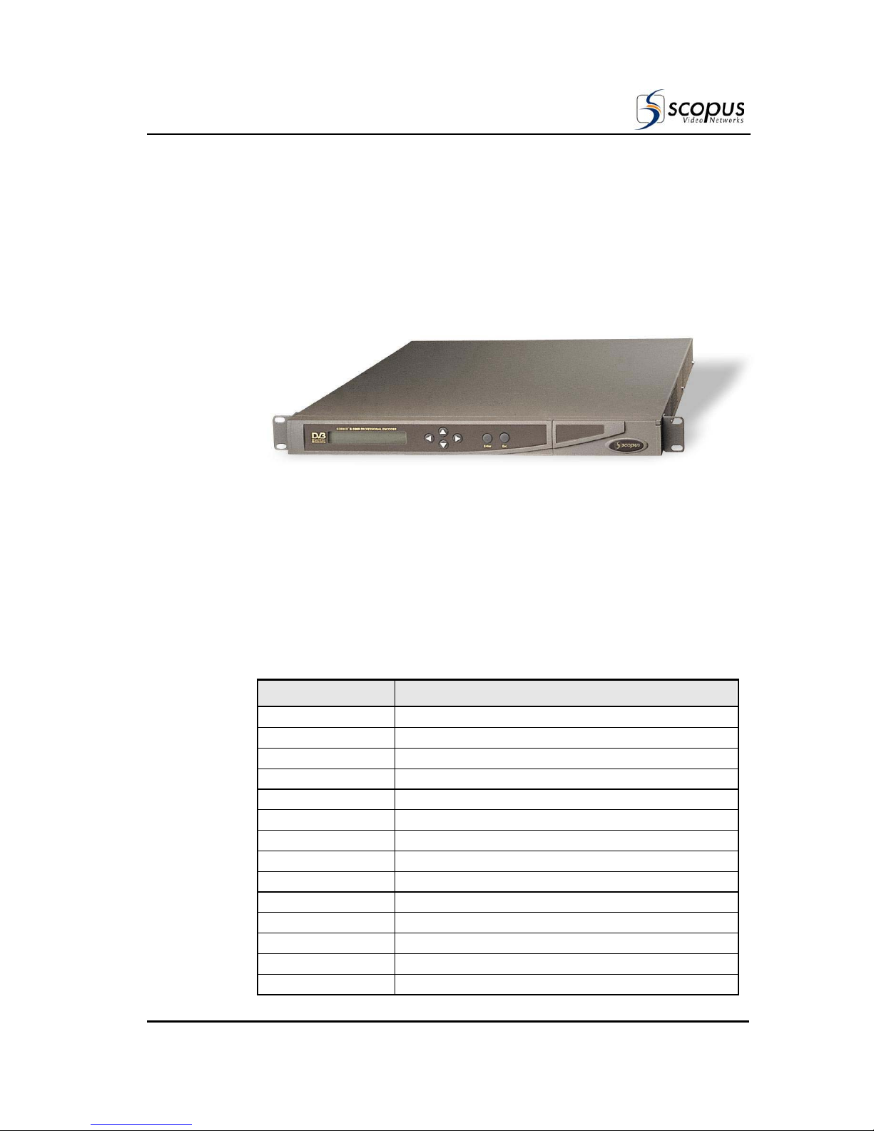
Scopus CODICO E-1710 User manual

CODICO®E-1710&1720
Compact DSNG Encoders
USER MANUAL
SCOPUS DOCUMENTS (P/N100401)
REV. 1.3 / JULY 2005)


CODICO®E-1710&1720
Compact DSNG Encoders
USER MANUAL
SCOPUS DOCUMENTS (P/N100401)
(REV. 1.3 / JULY 2005)


Scopus Video Networks Ltd.
International Headquarters
Scopus Video Networks Inc.
Americas
10 Ha’amal St., Park Afek
Rosh Ha’ayin, 48092
Israel
100 Overlook Center Drive, 3rd Floor
Princeton, NJ 08540.
USA
Tel: (972) –3-9007777
Fax: (972) –3-9007888
Tel: (609)-987-8090
Fax: (609)-987-8095
Email: [email protected]
Web: www.scopus.net
Email: info@scopususa.com
Web: www.scopususa.com
DOCUMENT HISTORY
VERSION DATE DETAILS
Rev. 1.0 Oct. 2004 E-1000 / 5.03 software version
Rev. 1.1 Mar. 2005 Documentation about Configuration files was added. Minor updates
Rev. 1.2 May 2005 General Update
Rev. 1.3 July 2005 RF DC Input update
© 2005 Scopus Video Networks Ltd. All rights reserved.
Scopus Video Networks Ltd. Reserves the rights to alter the equipment specifications and descriptions in this publication without prior notice. No
part of this publication shall be deemed to be part of any contract or warranty unless specifically incorporated by reference into such contract or
warranty.
The information contained herein is merely descriptive in nature, and does not constitute a binding offer for sale of the product described herein.
Specifications and features sets are for technical information and are not legally biding.
CODICO®is a Registered trademark of Scopus Video Networks Ltd. In Israel, Germany, France, U.K. U.S.A. and Japan. All references to registered
trademarks of other vendors are the property of their respective owners.
File E-1710&1720 User Rev 1.3 ido. Saved 8/30/2005 12:18 PM


CODICO®E-1710&1720
Compact DSNG Encoders
Scopus Documents (p/n 100401) Page i
INTRODUCTION
Scopus Video Networks Ltd. takes great pride in delivery of its products, and makes
every endeavor to ensure its clients full satisfactory.
On behalf of all the Scopus team, we would like to extend our congratulations on
your investment in the CODICOE-1710/1720 Compact DSNG Encoders.
E-1710/1720 COMPACT DSNG ENCODER
CODICO®PRODUCT LINE
The E-1710&1720 Compact DSNG Encoders are integral members of the advanced
CODICOproduct line.
The CODICOproduct family offers comprehensive solutions for both transmission
sites and reception stations. In addition, it is the most cost-effective solution for TV
broadcasting applications.
The following table lists the CODICO®product family and the illustration shows the
integration of the members in the product line in a DVB environment.
PRODUCT
DESCRIPTION
E-90 Entry Level MPEG-2 Encoders
E-900A Audio Professional Encoders
E-900/E-1000 MPEG-2 Professional Encoders
E-1200 MPEG-2 Advanced Encoders
E-1800 HDTV Encoder
E-1510 DSNG Encoders and Up Converters
E-1710/1720 DSNG Encoders and Modulators/Exciters
MOD-6810 Line DSNG Modulator
IRD-2450 HDTV Integrated Receiver Decoder
IRD-2600/IRD-2800 Advanced Professional Integrated Receiver Decoders
CID-3100 Common Interface Decryptor
RTM-3300 Compact DVB Re-Multiplexer and Stream Processor
RTM-3800 Series DVB Multiplexers
IVG-7000 Series Intelligent Video Gateways

User Manual
Front Matter
Page ii Rev. 1.3 / July 2005)
PRODUCT
DESCRIPTION
RSW-7x00 Series Redundancy Switches
NMS-4000 Family Complete Network Management System
CAS-5000 Series Conditional Access System
SM-30x0 Series Statistical Multiplexing Systems
SI-3050 Series PSI/SI Generator Applications

CODICO®E-1710&1720
Compact DSNG Encoders
Scopus Documents (p/n 100401) Page iii
MANUAL SCOPE AND STRUCTURE
The User Manual for the CODICOE-1710/1720 Compact DSNG Encoders provides
instructions for qualified installation, service and operation technicians to facilitate
optimum performance of the E-1710/1720 in a Digital Video Broadcasting System.
The manual is comprised of four main chapters:
1. OVERVIEW:
This chapter provides introduction and product description, including
highlights, benefits and typical applications, gives a functional and physical
description of the unit and lists its main capabilities and specifications.
2. INSTALLATION:
This chapter provides data and procedures required to install and activate the
unit. Procedures include site preparation and requirements, installation in a
19" rack, cable connections, panel options and Pin-out descriptions, initial
settings and serviceability check.
3. FRONT PANEL OPERATION:
This chapter provides theoretical background on the operation of the unit,
and gives data and instructions on using the unit and operating the control
and monitoring functions provided to the user from the E-1710/1720 Front
Panel.
4. CONFIGURATION FILES:
This chapter provides information about the E-1710/1720 configuration
through the configuration file “config.cfg”.
It is assumed throughout this document that personnel have a general knowledge
about the CODICO®E-1710/1720 Compact DSNG Encoders, application and
capabilities.
General knowledge of the CODICO®System and its application is also assumed. For
detailed information, refer to the CODICO®MPEG-2 DVB Family Product Description
documents.
TECHNICAL SUPPORT
In case of technical problems with the CODICOsystem or one of its components
please refer to the System Documentation. In most instances, this may save you
time in resolving technical difficulties.
Should you not be able to resolve the problem please call your local distributor for
technical support.

User Manual
Front Matter
Page iv Rev. 1.3 / July 2005)
HOW TORETURN FAULTY PARTS
Before Returning An Item:
xRequest a RMA (Return Merchandise Authorisation) Tracking Number from
your local Distributor.
xScopus Video Networks Support will assign a RMA Tracking Number; this
must accompany the item being returned and will be referred to in all
correspondence.
xSend the item to Scopus Video Networks with the RMA Number included in
the accompanying documentation (shipping and customs forms).
Customer Support Point Of Contact (POC)
Scopus Video Networks Inc.
U.S. Offices
Scopus Video Networks Ltd.
International Headquarters
100 Overlook Center Drive, 3rd Floor
Princeton, NJ 08540.
USA
10 Ha’amal St., Park Afek
Rosh Ha’ayin, 48092
Israel
Tel: (609)-987-8090
Fax: (609)-987-8095
Tel: (972) –3-9007777
Fax: (972) –3-9007888
Web: www.scopus.net

CODICO®E-1710&1720
Compact DSNG Encoders
Scopus Documents (p/n 100401) Page v
Warranty
SCOPUS Video Networks Ltd. warrants that the product and any part thereof, including but not
limited to spare parts, will, when properly installed, conform to SCOPUS Video Networks Ltd.
published specifications and that the product and any parts thereof, including but not limited to
spare parts, will be free from defects deriving from faulty workmanship and faulty materials
under standard use and service, for a period of twelve (12) months following the date of
manufacture thereof.
The supply of spare parts at a reasonable cost shall be available for a period of three (3) years
from the date of delivery.
This warranty does not cover ordinary wear and tear of the product or other defects due to
circumstances beyond SCOPUS Video Networks Ltd. Control, such as: unsuitable operating
means, chemical, Electro-mechanical or electrical influences and damages, which may be caused
by interference by the CUSTOMER or any unauthorized third party.
Defective cards and assemblies will be sent to SCOPUS Video Networks Ltd. for repair. The
repaired cards and assemblies will be returned to the CUSTOMER within 30 days from their
receipt by SCOPUS Video Networks Ltd.
Cards and assemblies repaired during the twelve (12) month warranty period will carry a
warranty of six (6) months from date of repair or until the end of original warranty period,
whichever is the later date.
SCOPUS Video Networks Ltd. sole liability under this warranty shall be limited to the repair or
replacement with equivalent units at SCOPUS Video Networks Ltd. facilities, of any product or
parts thereof that do not conform to SCOPUS Video Networks Ltd. published specifications or that
are defective in material or workmanship, as specified above. The expense of installing repaired
or replaced parts shall be borne by the CUSTOMER.
SCOPUS Video Networks Ltd. sole obligation under this warranty is to be the supplier of the
product to the CUSTOMER and to provide such services as set out in this warranty on the SCOPUS
Video Networks Ltd. terms and conditions provided for herein. In no event will SCOPUS Video
Networks Ltd. be liable to the CUSTOMER for any business expenses, loss of profits, incidental,
indirect or consequential damages, however caused, unless such expenses, loss or damages,
shall have derived from an infringement of patents of copyrights.
THE WARRANTIES STATED HEREIN ARE EXCLUSIVE AND ARE EXPRESSLY IN LIEU OF ALL OTHER
WARRANTIES, EXPRESSED OR IMPLIED, INCLUDING, BUT NOT LIMITED TO, THE IMPLIED
WARRANTY OF MERCHANTABILITY OR FITNESS FOR A PARTICULAR PURPOSE.
Beyond the warranty period, SCOPUS Video Networks Ltd. shall repair or replace defective cards
and assemblies according to its standard price list relevant at such time. Cards and assemblies
thus repaired shall carry a warranty of six (6) months.

User Manual
Front Matter
Page vi Rev. 1.3 / July 2005)
TABLE OF CONTENTS
Chapter 1 Overview ............................................................................................. 1-1
1.1. General Information ....................................................................................................... 1-1
1.1.1. Highlights and Benefits.........................................................................................1-2
1.1.2. Applications ..........................................................................................................1-5
1.1.2.1. Single Path DSNG Uplink Application ............................................................1-5
1.1.2.2. Cascading E-1710 Encoders .............................................................................1-7
1.1.2.3. Input Encoding Capability ................................................................................1-7
1.2. Functional Description .................................................................................................... 1-8
1.3. Mechanical Structure .................................................................................................... 1-10
1.3.1. Enclosure.............................................................................................................1-10
1.3.2. Front Panel ..........................................................................................................1-10
1.3.3. Rear Panel ...........................................................................................................1-11
1.4. E-1710/1720 Interfaces ................................................................................................ 1-12
1.4.1. Video Input Interfaces.........................................................................................1-12
1.4.1.1. Composite/SDI Video Input Panel (Option)...................................................1-12
1.4.1.2. Composite/Component Video Input Panel (Option).......................................1-14
1.4.2. E-1710/1720 Audio Input Interfaces...................................................................1-15
1.4.2.1. Standard Audio-1 and Audio-2 Interface........................................................1-15
1.4.2.2. Optional Audio-3 and Audio-4 Interface........................................................1-15
1.4.2.3. Optional Dolby-3 and Dolby-4 Interface........................................................1-17
1.4.3. E-1710 Data Input Interface................................................................................1-17
1.4.4. E-1710 Output Interfaces ....................................................................................1-18
1.4.4.1. ASI Output Interface.......................................................................................1-18
1.4.4.2. Modulated IF Output Interface .......................................................................1-18
1.4.4.3. L-Band Monitor Output Interface ...................................................................1-19
1.4.4.4. RS-422 Output Interface .................................................................................1-19
1.4.5. E-1720 Output Interfaces ....................................................................................1-19
1.4.5.1. ASI Output Interface.......................................................................................1-20
1.4.5.2. Modulated IF Output Interface .......................................................................1-20
1.4.5.3. L-Band Broadcast Output ...............................................................................1-20
1.4.5.4. L-Band Monitor Output Interface ...................................................................1-20
1.4.5.5. Ref 10 MHz.....................................................................................................1-20
1.4.5.6. RF DC Input....................................................................................................1-20
1.4.6. E-1710/1720 Control Interfaces..........................................................................1-21
1.4.6.1. GPI Interface...................................................................................................1-21
1.4.6.2. Ethernet Interface............................................................................................1-21
1.4.6.3. Monitor Output ...............................................................................................1-22
1.5. Management................................................................................................................ 1-23
1.5.1. Front Panel Control.............................................................................................1-23
1.5.2. TFTP Interface ....................................................................................................1-23
1.5.3. ASCII ..................................................................................................................1-23
1.5.4. SNMP Management............................................................................................1-24
1.6. Capabilities and Specifications....................................................................................... 1-25

CODICO®E-1710&1720
Compact DSNG Encoders
Scopus Documents (p/n 100401) Page vii
1.6.1. Capabilities ......................................................................................................... 1-25
1.6.2. Interface Connections Specifications ................................................................. 1-28
1.6.3. Physical Specifications ....................................................................................... 1-31
Chapter 2 Installation ......................................................................................... 2-1
2.1. General ..........................................................................................................................2-1
2.2. Installation Information...................................................................................................2-1
2.2.1. Safety Precautions ................................................................................................ 2-1
2.2.2. Inventory Check ................................................................................................... 2-2
2.2.3. Site Preparation .................................................................................................... 2-2
2.3. Mechanical Installation....................................................................................................2-3
2.3.1. Rack Mounting ..................................................................................................... 2-3
2.3.2. Compact Flash Installation ................................................................................... 2-3
2.4. Electrical Installation .......................................................................................................2-4
2.4.1. Power and Ground................................................................................................ 2-4
2.4.1.1. AC Power Supply ............................................................................................. 2-4
2.4.1.2. DC Power Supply ............................................................................................. 2-5
2.4.2. Cabling Connections ............................................................................................ 2-5
2.5. Quick Start Sequence......................................................................................................2-6
2.5.1. Power Up and Initialization Sequence.................................................................. 2-6
2.5.2. Initial Configuration ............................................................................................. 2-8
2.5.3. Immediate Modulator Upconverter Set-Up.......................................................... 2-9
2.5.4. Pre-Programmed Configurations........................................................................ 2-10
2.5.5. Remote to Local Control Transfer...................................................................... 2-11
2.6. Serviceability Checks.....................................................................................................2-12
2.6.1. Video Serviceability Check ................................................................................ 2-12
2.6.2. Audio Serviceability Check................................................................................ 2-13
2.6.3. Modulator Serviceability Test ............................................................................ 2-14
Chapter 3 Encoder Front Panel Operation........................................................... 3-1
3.1. Introduction ...................................................................................................................3-1
3.1.1. Front Panel Theory of Operation.......................................................................... 3-1
3.1.2. Front Panel Menu - Parameters Management Concept........................................ 3-3
3.1.2.1. CHOOSE Step:................................................................................................. 3-3
3.1.2.2. CHANGE Step: ................................................................................................ 3-3
3.1.2.3. SAVE Step: ...................................................................................................... 3-4
3.1.3. Front Panel Menu ................................................................................................. 3-5
3.2. Encoder Configuration Menu............................................................................................3-7
3.2.1. Encoder Configuration Menu Overview .............................................................. 3-7
3.2.1.1. Encoder Configuration Menu Structure ........................................................... 3-7
3.2.1.2. Encoder Configuration Menu Operation .......................................................... 3-9
3.2.2. Video Configuration Menu................................................................................. 3-10
3.2.2.1. Video Format Configuration .......................................................................... 3-12
3.2.2.2. Video Source Configuration........................................................................... 3-12
3.2.2.3. Output Rate Configuration ............................................................................. 3-13
3.2.2.4. Video Rate Configuration............................................................................... 3-13
3.2.2.5. Video Resolution Configuration..................................................................... 3-14
3.2.2.6. Video Profile Configuration ........................................................................... 3-15

User Manual
Front Matter
Page viii Rev. 1.3 / July 2005)
3.2.2.7. Luminance Temporal Configuration...............................................................3-15
3.2.2.8. Chrominance Temporal Configuration ...........................................................3-16
3.2.2.9. Luminance Vertical Configuration .................................................................3-16
3.2.2.10. Chrominance Decimation Configuration.....................................................3-17
3.2.2.11. Horizontal Filter Configuration ....................................................................3-17
3.2.3. Audio Configuration Menu.................................................................................3-18
3.2.4. Audio MUSICAM Configuration Sub-Menu .....................................................3-20
3.2.4.1. Audio #1, #2 Source Configuration ................................................................3-20
3.2.4.2. Audio #1, #2 Rate Configuration....................................................................3-21
3.2.4.3. Audio #1, #2 Level Configuration ..................................................................3-21
3.2.4.4. Audio Sample Rate Configuration..................................................................3-22
3.2.5. Audio Dolby Configuration Sub-Menu ..............................................................3-23
3.2.5.1. Dolby Data Rate Configuration ......................................................................3-23
3.2.5.2. Dolby Coding Mode Configuration ................................................................3-24
3.2.5.3. Dolby Sample Frequency Configuration ........................................................3-24
3.2.5.4. Dolby Bit Stream Mode Configuration...........................................................3-25
3.2.5.5. Dolby Dialog Level Configuration .................................................................3-25
3.2.5.6. Dolby Surround Mode Configuration .............................................................3-26
3.2.5.7. Dolby Mixing Level Configuration ................................................................3-26
3.2.5.8. Dolby Room Type Configuration ...................................................................3-26
3.2.5.9. Dolby Copy Right Configuration....................................................................3-27
3.2.5.10. Dolby Original Configuration.......................................................................3-27
3.2.5.11. Dolby Audio Source Configuration ..............................................................3-27
3.2.5.12. Dolby DYN RNG PRF Configuration..........................................................3-28
3.2.5.13. Dolby RF OVERMD PRT Configuration.....................................................3-28
3.2.5.14. Dolby LP Filter Configuration......................................................................3-28
3.2.5.15. Dolby DC Notch Configuration....................................................................3-29
3.2.6. Auxiliary Configuration Menu ...........................................................................3-29
3.2.6.1. High Speed Data Rate Configuration..............................................................3-31
3.2.6.2. High Speed Clock Rate Configuration............................................................3-31
3.2.6.3. VBI Fields Configuration................................................................................3-32
3.2.6.4. Teletext Source Configuration ........................................................................3-33
3.2.6.5. BISS Items Menu Configuration.....................................................................3-33
3.2.6.6. Clock Type Configuration ..............................................................................3-33
3.2.7. BISS Items Configuration Sub-Menu.................................................................3-34
3.2.7.1. Clear / No Scrambling Configuration .............................................................3-35
3.2.7.2. BISS Mode-1 Scrambling Configuration........................................................3-36
3.2.7.3. BISS-E Buried ID Scrambling Configuration ................................................3-37
3.2.7.4. BISS-E Injected ID Scrambling Configuration ..............................................3-38
3.2.8. Service Configuration Menu...............................................................................3-39
3.2.9. Advanced Services Configuration Sub-Menu.....................................................3-41
3.2.9.1. Aspect Ratio Configuration ...........................................................................3-41
3.2.9.2. Framing Type Configuration .........................................................................3-42
3.2.9.3. Program Number Configuration ....................................................................3-42
3.2.9.4. Cascading Configuration.................................................................................3-42
3.2.9.5. Audio to Video Sync Configuration ...............................................................3-43

CODICO®E-1710&1720
Compact DSNG Encoders
Scopus Documents (p/n 100401) Page ix
3.2.9.6. DVB Tables Configuration............................................................................ 3-43
3.2.9.7. GOP Structure Configuration ........................................................................ 3-44
3.2.9.8. GOP Size Configuration................................................................................. 3-44
3.2.9.9. Video PID Configuration ............................................................................... 3-45
3.2.9.10. Audio#1 PID Configuration ......................................................................... 3-45
3.2.9.11. High Speed Data PID Configuration ............................................................ 3-46
3.2.9.12. Teletext PID Configuration .......................................................................... 3-46
3.2.9.13. PCR PID Configuration................................................................................ 3-46
3.2.9.14. PMT PID Configuration ............................................................................... 3-47
3.2.9.15. IP Number Configuration ............................................................................. 3-47
3.2.9.16. Default Gateway Configuration.................................................................... 3-47
3.2.9.17. Subnet Mask Configuration.......................................................................... 3-48
3.2.10. Pre-Processing Services Configuration Menu.................................................... 3-48
3.2.10.1. PrePro Enable Configuration........................................................................ 3-48
3.2.11. A/D Services Configuration Sub-Menu ............................................................. 3-48
3.2.11.1. Restore Default Setup................................................................................... 3-50
3.2.11.2. Luminance Configuration............................................................................. 3-50
3.2.11.3. Chrominance Configuration ......................................................................... 3-51
3.2.11.4. Offset Level Configuration........................................................................... 3-52
3.2.11.5. Y-C Delay Configuration ............................................................................. 3-52
3.2.11.6. Dig. Noise Red. Configuration ..................................................................... 3-52
3.2.12. Other Service Configuratrion Sub-Menu ........................................................... 3-53
3.2.12.1. Recall Setup.................................................................................................. 3-53
3.2.12.2. Save Setup .................................................................................................... 3-54
3.2.12.3. Service Name Configuration ........................................................................ 3-54
3.2.12.4. Reset Type Configuration............................................................................. 3-55
3.2.12.5. Panel Contrast Configuration ....................................................................... 3-55
3.3. Encoder Status Menu ....................................................................................................3-56
3.3.1. System Status Menu ........................................................................................... 3-57
3.3.1.1. Video Rate Display......................................................................................... 3-57
3.3.1.2. Audio Rate Display ........................................................................................ 3-57
3.3.1.3. LS Data Rate Display ..................................................................................... 3-57
3.3.1.4. HS Data Rate Display..................................................................................... 3-57
3.3.1.5. TTX Data Rate Display .................................................................................. 3-57
3.3.2. General Status Menu .......................................................................................... 3-58
3.3.2.1. Encoder Software Version Display ................................................................ 3-58
3.3.2.2. Encoder Hardware Version Display ............................................................... 3-58
3.3.2.3. Encoder Type Display .................................................................................... 3-58
3.3.2.4. Video Interface Display.................................................................................. 3-58
3.3.2.5. Audio Channels Display................................................................................. 3-59
3.3.2.6. DVB Scrambler Board Display ...................................................................... 3-59
3.3.2.7. Temperature Display ...................................................................................... 3-59
3.4. Encoder Test Menu .......................................................................................................3-60
3.4.1. Test menuÆAudio test....................................................................................... 3-61
3.4.2. Test menuÆVideo test ....................................................................................... 3-61
3.5. Modulator Menu............................................................................................................3-62

User Manual
Front Matter
Page x Rev. 1.3 / July 2005)
3.5.1. Modulator Configuration Menu..........................................................................3-64
3.5.1.1. Symbol Rate Configuration ............................................................................3-64
3.5.1.2. Output Rate Configuration..............................................................................3-64
3.5.1.3. Modulation Set-Up..........................................................................................3-65
3.5.1.4. FEC Modulator Set-Up ...................................................................................3-65
3.5.1.5. IF Frequency Set-Up.......................................................................................3-65
3.5.1.6. L Band Frequency Set-Up...............................................................................3-66
3.5.1.7. KU Frequency Set-Up.....................................................................................3-66
3.5.1.8. Output Level Set-Up .......................................................................................3-67
3.5.1.9. Spectral Inversion Status Set-Up ....................................................................3-67
3.5.1.10. Excess Bandwidth level Set-Up....................................................................3-67
3.5.1.11. IF Level Set-Up.............................................................................................3-68
3.5.1.12. L-Band DC out Set-Up .................................................................................3-68
3.5.1.13. Framing Type................................................................................................3-68
3.5.2. Modulator Status Menu.......................................................................................3-69
3.5.2.1. Modulator Status.............................................................................................3-70
3.5.2.2. Modulator Board .............................................................................................3-70
3.5.3. Modulator Run Menu..........................................................................................3-70
3.5.3.1. UP Converter Output Set-Up ..........................................................................3-70
3.5.3.2. Output Level Set-Up .......................................................................................3-71
Chapter 4 Configuration Files.............................................................................. 4-1
4.1. Using VI Editor to Edit the Configuration File.................................................................... 4-1
4.2. E-1710/1720 Configuration File ....................................................................................... 4-6
4.2.1. E-1710/1720 Parameters .......................................................................................4-6
4.2.2. E-1710 only.........................................................................................................4-11
4.2.3. E-1720 only.........................................................................................................4-13

CODICO®E-1710&1720
Compact DSNG Encoders
Scopus Documents (p/n 100401) Page xi
LIST OF FIGURES
Figure 1-1: The CODICOE-1710 Compact DSNG Encoders – General View .................1-1
Figure 1-2: Single Path DSNG Uplink Application.........................................................1-5
Figure 1-3: CODICOE-1710/1720 Compact DSNG Encoders in an SCPC application.....1-7
Figure 1-4: DSNG Encoder - Functional Block Diagram ................................................1-9
Figure 1-5: Front View of the E-1710/1720 DSNG Encoder ........................................ 1-10
Figure 1-6: E-1710 DSNG Encoder - Rear View ......................................................... 1-11
Figure 1-7: E-1720 DSNG Encoder – Rear View......................................................... 1-11
Figure 1-8: Composite/SDI Video Input Panel ........................................................... 1-12
Figure 1-9: Composite/Component Video Input Panel ............................................... 1-14
Figure 1-10: E-1000 Audio Input Options ................................................................... 1-15
Figure 1-11: E-1710 Data Input Options..................................................................... 1-17
Figure 1-12: E-1710 Output Options .......................................................................... 1-18
Figure 1-13: E-1720 Output Options .......................................................................... 1-19
Figure 1-14: E-1710/1720 Control Interfaces Connections........................................... 1-21
Figure 2-1: E-1710 Rear Panel, AC Power Connection .................................................2-4
Figure 2-2: E-1710/1720 Rear Panel, DC Power Connection ........................................2-5
Figure 2-3: E-1710 Typical Rear Panels – Connectors Location ....................................2-5
Figure 2-4: DSNG Encoder Front Panel.......................................................................2-9
Figure 3-1: Front View of the Encoder........................................................................3-1
Figure 3-2: Encoder Front Panel Menu - Structure.......................................................3-6
Figure 3-3: Encoder Configuration Menu Tree.............................................................3-8
Figure 3-4: Video Menu........................................................................................... 3-11
Figure 3-5: Audio Menu........................................................................................... 3-19
Figure 3-6: Auxiliary Menu....................................................................................... 3-30
Figure 3-7: Service Menu ........................................................................................ 3-40
Figure 3-8: Encoder Status Menus ........................................................................... 3-56
Figure 3-9: Encoder Test Menus .............................................................................. 3-60
Figure 3-10: RF Modulator (Modem) Menu ................................................................. 3-62
LIST OF TABLES
Table 1-1: E-1710/1720 DSNG Encoder Capabilities ................................................. 1-25
Table 1-2: Input Connection Interfaces ................................................................... 1-28
Table 1-3: Mechanical Dimensions .......................................................................... 1-31
Table 1-4: E-1710/1720 Electrical Requirements...................................................... 1-31
Table 1-5: E-1710/1720 Environmental Conditions................................................... 1-32
Table 2-1: CODICOE-1710/1720 Compact DSNG Encoders Inventory List .................2-2
Table 2-2: Encoder Status Indicator LED Legend .......................................................2-7
Table 3-1: Front Panel Controls and Indicators ..........................................................3-2
Table 3-2: Modem Menu Options ............................................................................ 3-63
Table 4-1: VI Editor Modes.......................................................................................4-2
Table 4-2: VI Commands and Syntax ........................................................................4-4


CODICO®E-1710&1720
Compact DSNG Encoders
Scopus Documents (p/n 100401) Page 1-1
Chapter 1
OVERVIEW
1.1. GENERAL INFORMATION
The CODICOE-1710/1720 Compact DSNG Encoders are a fully integrated
MPEG-2 4:2:2 encoder/modulator in a 1 RU high unit, thus, it is particularly
suitable for the fast-moving world of digital satellite news gathering (DSNG)
contribution applications.
The E-1710 features, within the compact 1U enclosure, an advanced
professional broadcast quality encoder and a software modifiable QPSK, 8PSK
16QAM modulator with embedded L-Band Monitoring. The E-1720 adds an L-
Band Up-Converter that provides broadcast quality L-Band signal.
The E-1710/1720 is a rugged, power efficient and user-friendly
encoder/modulator. It is fully compliant to both 4:2:0 and 4:2:2 DVB standards,
ensuring best picture quality at a competitive price in a compact unit. Figure 1-1
illustrates the
E-1710/1720.
Figure 1-1: The CODICOE-1710 Compact DSNG Encoders – General View
For any type of SNG uplink system, the E-1710/1720 fits neatly into the rack,
occupying only 1U with no need to provide space for ventilation above or below.
The L-band Monitoring Output, provided by the E-1710/1720, enables “on the
spot” real-time monitoring of the modulated transmit information.
In addition, the E-1720 provides an up converter that outputs a Broadcast
quality L-Band signal. The E-1720 also provides an external/internal accurate
10Mhz clock and +24DC power for BUC devices.

User Manual
Overview
Page 1-2 Rev. 1.3 / July 2005)
1.1.1. Highlights and Benefits
The E-1710/1720 offers 10 bit coding at data rates of up to 52 Mbps while the
versatile on-board modulator can handle QPSK transmissions with 8-PSK or
16-QAM modes as an option. A variety of video resolutions are available as
standard, as is advanced DNR (Digital Noise Reduction).
The E-1710/1720 also offers a DVB-compliant Low-Delay mode in either 4:2:0
or 4:2:2 format. A special Ultra-Low mode is provided for the 4:2:2 format to
enhance two-way transmission for DSNG and live interviews.
Offering 70 MHz output and a Broadcast quality L-Band signal (E-1720 only).
The E-1710/1720 can be installed remote from the Up Converter/HPA package,
enabling cross-site distances in excess of 25 meters if required (dependent upon
cable type). The L-band Monitoring Output provides local monitoring of the
modulated output.
The Front Panel Operating Menu provided by the E-1710/1720 is specifically
tailored to SNG, with frequently used operation critical controls such as ‘carrier
on/off’ and ‘modulation on/off’ available via ‘hot-keys’ on the front panel four
way touch pad. This allows the operator to get up onto or off the satellite
rapidly. This feature, combined with the facility to store up to 10 pre-set
configurations, gives the E-1710/1720 unrivalled flexibility for the busy operator.
E-1710/1720 handles up to four full quality stereo audio channels (or up to 8
mono channels) as either analogue/SDI embedded/AES inputs, with a range of
sampling rates and coding rates of up to 384 Kbps.
The E-1710/1720 features fully compliant BISS (Basic Interoperability
Scrambling System) in either BISS Mode 1 or BISS-E to protect those all-
important transmissions using the industry security standard.
The E-1710 provides multi-channel encoder cascading. This standard facility
enables a single Master E-1710 Encoders and multiple E-1000 Professional
Encoders to be configured to offer a single-stream output containing multiple
programs. This offers an ideal solution for multi-channel systems and saves the
cost of a separate multiplexing device.
Following is a detailed list of the capabilities and benefits provided by the
CODICOE-1710/1720 Compact DSNG Encoders.
Other manuals for CODICO E-1710
1
This manual suits for next models
1
Table of contents
Other Scopus Media Converter manuals