Integratech SR-2421-ZG-PUSH User manual
Drukknop dimmer 1-10V/easy DALI
SR-2421-ZG-PUSH
Armaturen met 1-10V/DALI driver bedienen met een drukknop
Technische parameters
INPUT
Aansluitspanning 110-240VAC
Bediening drukknop/Zigbee
Output 0/1-10V Max 20mA
DALI Max 50mA
Omgevingstemp -20~+50°C
Luchtvochtigheid 8~80%
Afmetingen 80x36x20,5mm
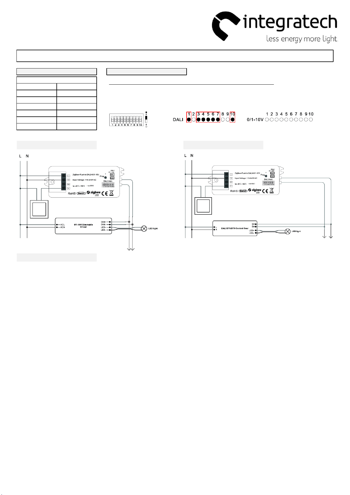
Instelling
Bij het aanpassen van de DIP-switch instellingen steeds de spanning uitschakelen!
1. Kies de gewenste uitgangsmodus 1-10 of DALI
DALI DT6 modus (broadcast) = DIP-SWITCH 1+3+4+5+6+7+10 op ON
0/1-10V modus = Alle DIP-SWITCH op OFF
ON
OFF
Aansluitschema 1-10V modus
drukknop
Aansluitschema DALI modus
drukknop
Max
20mA Max 50mA
(25 DALI drivers)
Bediening
Kort drukken = aan/uit
Lang drukken = dimmen
01/07/2022

Zigbee+Push to DALI+0/1-10V Converter
09.2421ZGP.04791
Function introduction
Important: Read All Instructions Prior to Installation
Product Data
• DO NOT set the DIP switches with power applied to the device.
• DO NOT install with power applied to device.
• DO NOT expose the device to moisture.
Safety & Warnings
• Zigbee+Push to DALI+0/1-10V converter based on zigbee 3.0
• Zigbee signal input & push switch input, DALI output to DALI line or 0/1-10V signal output, 110-240VAC power input
• Can be controlled by both Zigbee signal & push switch input
• Integrates existing push switch into DALI or 0/1-10V
• Compatible with universal Zigbee gateway or hub products
• Can directly pair to a compatible ZigBee remote via Touchlink
• Compatible with universal Zigbee remotes
• Supports self-forming zigbee network without coordinator
• Supports find and bind mode to bind a ZigBee remote
• Supports zigbee green power and can bind max. 20 zigbee green power switches
• DALI signal or 1-10V signal output selectable by DIP switch
• Built-in DALI bus power supply, no extra DALI bus PS required
• With max. 50mA DALI bus power current output
• To supply control current to up to 25 DALI control gears
• DALI DT6 or DT8 device type selectable by DIP switch under DALI mode
• Color control according to DALI specifications of Device Type 8,
• Color type: Tc, XY coordinates, RGBW selectable by DIP switches
• DALI address control mode or group control mode selectable by DIP switch
• Enables to select the DALI address (00-63) to be controlled by DIP switches
• Enables to select the DALI group (0-15) to be controlled by DIP switches
• Enable to control 1 DALI Group of devices or 1 DALI Address on DALI line
• Enable to control all devices on DALI line via broadcast
• Waterproof grade: IP20
Operation
110-240V
power input
DIM
DT8 Tc
1 2 345678
2) Select DALI Device Type (DT6/DT8 Color Type) to be Controlled Using Dial Switches 8-9
DT8 XY Coordinates
DT8 RGBW
1 2 345678
910
Address Mode
1 2 345678
3) Select DALI Address or Group Control Mode Using Dial Switch 7
Group Mode
1 2 34567899 10
DALI
1 2 345678
1) Select DALI or 0/1-10V Output Using Dial Switch 10
0/1-10V
1 2 345678910
910
1 2 3 4 5 6 7 8 9 10
Dial up
Dial down
Note: please first select output signal by the dial switch.
Note: once DALI output is selected, please then select the DALI device type you would like to control by
the dial switches.
Note: once DALI device type is selected, please then select address control mode or group control mode
by dial switch.
0
1
2
3
4
5
6
1 2 345678
4) Select the DALI Group to be Controlled Using Dial Switches 2-6
Note: here device type is selected as DIM as an example, please select your correct DALI device type.
9
10
11
12
13
14
15
1 2 34567
7
910
Controlled group Controlled group
Note: 1) once DALI device type and group control mode are selected, please then select the DALI group
(0-15 selectable) to be controlled on DALI line by dial switches.
2) The control gears that are assigned to the selected DALI group on DALI line will be controlled.
3) The control gears shall be first grouped by a DALI master controller, please refer to the user manual of
corresponding master controller.
8
8
910
10
910
1 2 3 4 5 6 7 8 9 10
Dial up
Dial down
1 2 3 4 5 6 7 8 9 10
Dial up
Dial down
1 2 3 4 5 6 7 8 9 10
Dial up
Dial down
Input
110-240VAC Max. 4mA Max. 20mA
Power Current Operating
temperature
-20℃-+50℃
Signal
Zigbee
2.4GHz
Output, DALI Output,
0/1-10V
DALI PS
current
Max. 50mA
DALI current
consumption
Relative
humidity
8% to 80%
Environment
Dimensions
95x37x20mm
Others
Broadcast
AC push
switch input
DALI (DA, DA)
or
0/1-10V output (+, -)
LED indicator
Program key, for network pairing, touchlink and factory reset of the device
Dip switches to select DALI or 0/1-10V output, DALI DT6 or DT8 color type, DALI address
or group control mode, DALI address to be controlled, DALI group to be controlled
DALI Add.
1 53 7 92 64 8 1 0
L
S
N
NC
DA/-
DA/+
Prog.
DALI
0/1-10V
Input Voltage: 110-240V AC
ZigBee+Push to DALI+0/1-10V
ta:-20℃-+50℃
Switch
1CH
Push

5) Select the DALI Address to be Controlled Using Dial Switches 1-6
Note: here device type is selected as DIM as an example, please select your correct DALI device type.
1 2 3456781 2 345678910
910
Controlled address Controlled address
00
01
02
03
04
05
06
07
08
09
10
11
12
13
14
15
16
17
18
19
20
21
22
23
24
25
26
27
28
29
30
31
32
33
34
35
36
37
38
39
40
41
42
43
44
45
46
47
48
49
50
51
52
53
54
55
56
57
58
59
60
61
62
63
Note: 1) once DALI device type and address control mode are selected, please then select the DALI address
(00-63 selectable) to be controlled on DALI line by dial switches.
2) The control gear with the selected DALI address on DALI line will be controlled.
1 2 3 4 5 6 7 8 9 10
Dial up
Dial down
6. ZigBee Clusters the device supports are as follows:
Input Clusters
• 0x0000: Basic • 0x0003: Identify • 0x0004: Groups • 0x0005: Scenes • 0x0006: On/off
• 0x0008: Level Control • 0x0300: Color Control • 0x0b05: Diagnostics
Output Clusters
• 0x0019: OTA
7. Do wiring according to connection diagram correctly.
8. This ZigBee device is a wireless receiver that communicates with a variety of ZigBee compatible
systems. This receiver receives and is controlled by wireless radio signals from the compatible ZigBee
system.
9. Zigbee Network Pairing through Coordinator or Hub (Added to a Zigbee Network)
10. TouchLink to a Zigbee Remote
Note: 1) Directly TouchLink (both not added to a ZigBee network), each device can link with 1 remote.
2) TouchLink after both added to a ZigBee network, each device can link with max. 30 remotes.
3) To control through both gateway and remote, add remote and device to gateway network first
then TouchLink
4) After TouchLink, the device can be controlled by the linked remotes.
Step 1: Remove the device from previous zigbee network if it has already been added to, otherwise pairing will
fail. Please refer to the part "Factory Reset Manually".
Step 2: From your ZigBee Controller or hub interface, choose to add lighting device and enter Pairing mode as
instructed by the controller.
Step 4: LED indicator will blink 5 times
and then stay solid on, then the device
will appear in your controller's menu
and can be controlled through
controller or hub interface.
Step 1: Method 1: Short press “Prog” button 4 times (or reset power of the device 4 times from master breaker) to
start Touchlink commissioning (lasts for 180S) immediately under any circumstances, once time out, repeat this
step.
Method 2: Reset power of the device, Touchlink commissioning will start after 15S if it’s not added to a zigbee
network, 165S timeout. Or start immediately if it’s already added to a network, 180S timeout. Once timeout, repeat
the step.
Step 3: Reset power of the device from master circuit breaker to set it into network pairing mode (connected
light flashes twice slowly), network pairing mode lasts 15S (enters into touchlink mode after 15S), once
timeout, repeat this step.
Step 4: There shall be indication on
the remote for successful link and LED
indicator on the device will flash twice.
Zigbee
Remote
Step 2: Bring the remote or touch panel within 10cm of the lighting device.
Step 3: Set the remote or touch panel into Touchlink commissioning,
please refer to corresponding remote or touch panel manual to learn how.
< 10cm
L N
L N
DALI Add.
1 53 7 92 64 8 10
L
S
N
NC
DA/-
DA/+
Prog.
DALI
0/1- 10V
Input Vo ltage: 110-2 40V AC
ZigBe e+Push to DALI+0/ 1-10V
ta:-2 0℃-+50℃
DALI Add.
1 53 7 92 64 8 10
L
S
N
NC
DA/-
DA/+
Prog.
DALI
0/1- 10V
Input Vo ltage: 110-2 40V AC
ZigBe e+Push to DALI+0/ 1-10V
ta:-2 0℃-+50℃
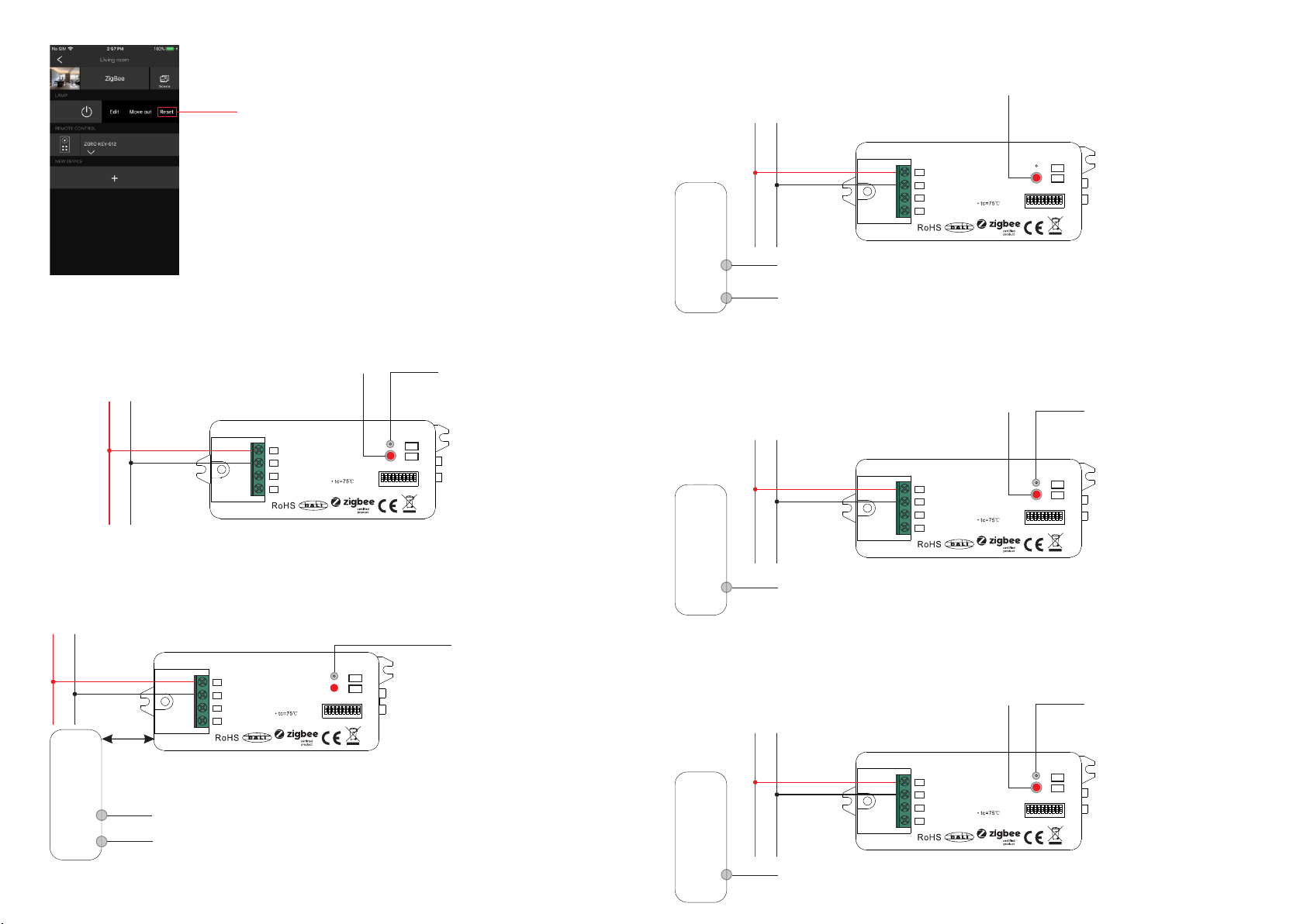
11. Removed from a Zigbee Network through Coordinator or Hub Interface
From your ZigBee controller or hub interface, choose to delete or reset
the lighting device as instructed. The connected light blinks 3 times to
indicate successful reset.
12. Factory Reset Manually
Note: 1) If the device is already at factory default setting, there is no indication when factory reset again .
2) All configuration parameters will be reset after the device is reset or removed from the network.
13. Factory Reset through a Zigbee Remote (Touch Reset)
14. Find and Bind Mode
Step 2: Set the remote or touch panel (target node) into find and bind mode, and enable it
to find and bind initiator, please refer to corresponding remote or touch panel manual.
Step 3: There shall be indication on the remote or touch panel that it bind the device
successfully and can control it then.
Zigbee
Remote
Step 1: Short press “Prog.” button 3 times (Or reset power of the device (initiator node) 3 times) to start Find and
Bind mode (connected light flashes slowly) to find and bind target node, 180 seconds timeout, repeat the step.
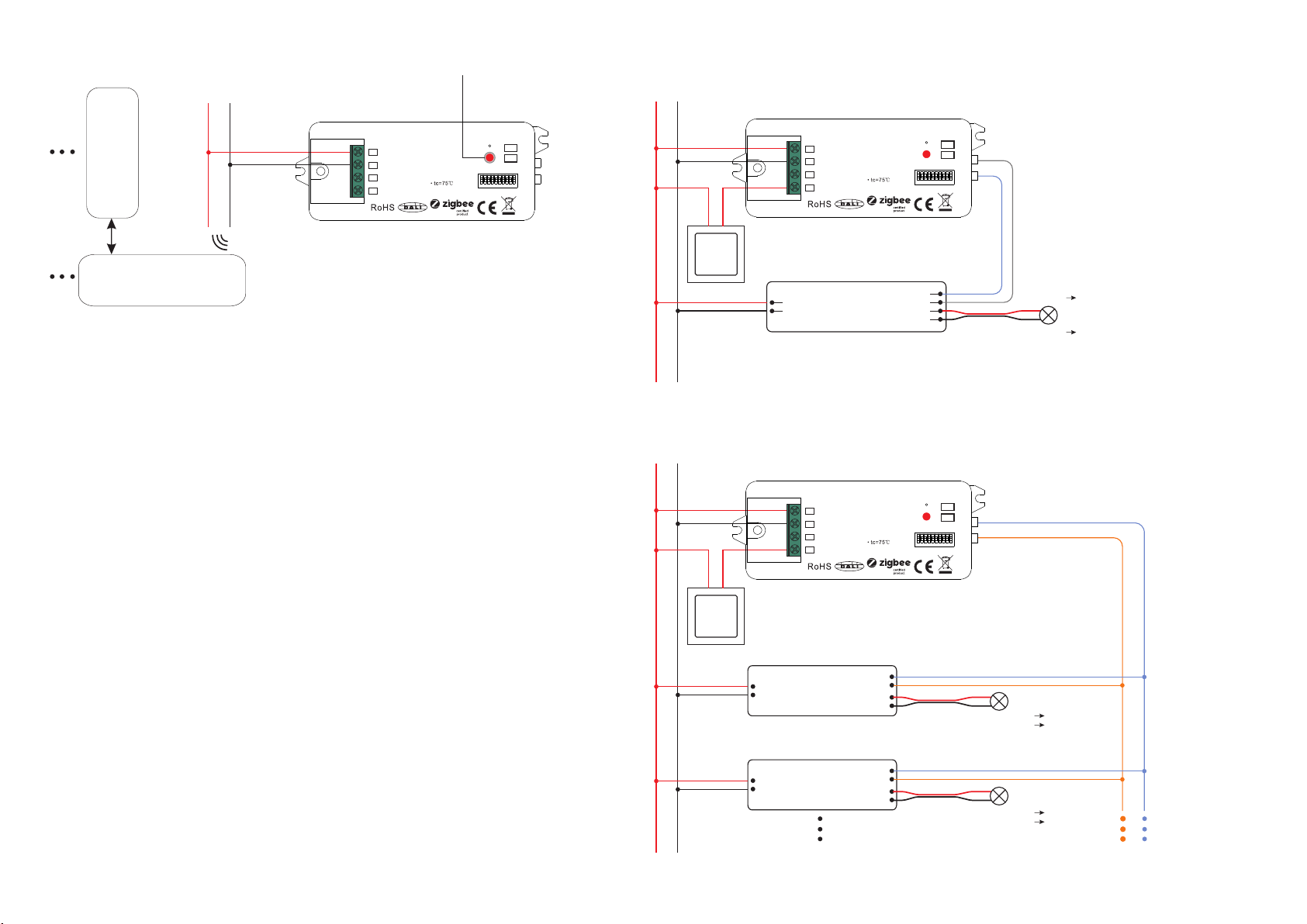
15. Learning to a Zigbee Green Power Switch
Step 2: Set the green power
switch into Learning mode,
please refer to its manual.
Zigbee
Green Po wer
Switch
Step 3: LED indicator will flash
twice to indicate successful
learning. Then the switch can
control the device.
Step 1: Short press “Prog.” button 4 times (Or reset power of the device 4 times) to start Learning to GP switch
mode (connected light flashes twice), 180 seconds timeout, repeat the step.
Note: Each device can learn to
max. 20 zigbee green power switches.
16. Delete Learning to a Zigbee Green Power Switch
Step 2: Set the paired green power switch into
Learning mode, please refer to its manual.
Step 3: LED indicator will
flash 4 times to indicate
successful deleting.
Step 1: Short press “Prog.” button 3 times (Or reset power of the device 3 times) to start delete Learning to GP
switch mode (connected light flashes slowly), 180 seconds timeout, repeat the step.
Step 1: Short press “Prog.” key for 5 times continuously or reset power of the device for 5 times continuously
from master breaker if the “Prog.” key is not accessible.
Step 3: Set the remote or touch panel into Touch Reset procedure to reset the
device, please refer to corresponding remote or touch panel manual to learn how.
Note: Make sure the device already added to a network, the remote added to the same one or not added to any
network.
Step 1: Reset power of the device to start TouchLink Commissioning, 180 seconds timeout, repeat this step.
Step 4: There shall be indication
on the remote and LED indicator
on the device flashes 3 times for
successful reset.
< 10cm
Zigbee
Remote
Zigbee
Green Po wer
Switch
Step 2: LED indicator flashes 3
times for successful reset.
Step 2: Bring the remote or touch panel within 10cm of the lighting device.
Note: Make sure the device and the remote or touch panel already added to the same Zigbee hub.
L N
L N
L N
L N
L N
DALI Add.
1 53 7 92 64 8 10
L
S
N
NC
DA/-
DA/+
Prog.
DALI
0/1- 10V
Input Vo ltage: 110-2 40V AC
ZigBe e+Push to DALI+0/ 1-10V
ta:-2 0℃-+50℃
DALI Add.
1 53 7 92 64 8 10
L
S
N
NC
DA/-
DA/+
Prog.
DALI
0/1- 10V
Input Vo ltage: 110-2 40V AC
ZigBe e+Push to DALI+0/ 1-10V
ta:-2 0℃-+50℃
DALI Add.
1 53 7 92 64 8 10
L
S
N
NC
DA/-
DA/+
Prog.
DALI
0/1- 10V
Input Vo ltage: 110-2 40V AC
ZigBe e+Push to DALI+0/ 1-10V
ta:-2 0℃-+50℃
DALI Add.
1 53 7 92 64 8 10
L
S
N
NC
DA/-
DA/+
Prog.
DALI
0/1- 10V
Input Vo ltage: 110-2 40V AC
ZigBe e+Push to DALI+0/ 1-10V
ta:-2 0℃-+50℃
DALI Add.
1 53 7 92 64 8 10
L
S
N
NC
DA/-
DA/+
Prog.
DALI
0/1- 10V
Input Vo ltage: 110-2 40V AC
ZigBe e+Push to DALI+0/ 1-10V
ta:-2 0℃-+50℃
Zigbee Lighting Device
17. Setup a Zigbee Network & Add Other Devices to the Network (No Coordinator Required)
Step 2: Set another device or remote or touch panel into network pairing mode and pair to the network, refer to
their manuals.
Step 3: Pair more devices and remotes to the network as you would like, refer to their manuals.
Step 4: Bind the added devices and remotes through Touchlink so that the devices can be controlled by the
remotes, refer to their manuals.
Note: 1) Each added device can link and be controlled by max. 30 added remotes.
2) Each added remote can link and control max. 30 added devices.
18. OTA
The device supports firmware updating through OTA, and will acquire new firmware from zigbee controller or
hub every 10 minutes automatically.
Step 1: Short press “Prog.” button 4 times (Or reset power of the device 4 times) to enable the device to form a
zigbee network (LED indicator flashes twice) to discover and add other devices, 180 seconds timeout, repeat
the step.
Zigbee
Remote
< 10cm TouchLink
0/1-10V Dimmable
Driver
ACL
ACN
DIM+
DIM-
LED+
Wiring Diagram
When 0/1-10V Output Selected
L N
LED+ V+
LED light
LED-
LED- V-
When DALI Output Selected
Note: Max. 50mA DALI bus PS output to supply control current to up to 25 control gears.
DALI Bus
DA
DA
DALI DT6/DT8 Control Gear
L
N
DA
DA
DALI DT6/DT8 Control Gear
L
N
LED+
LED-
LED+
LED-
LED+ V+
LED- V-
LED+ V+
LED- V-
LED light
LED light
L N
L N
19. Controlled through Push Switch
When DALI Output Selected
Ÿ Click the button to switch ON/OFF
Ÿ Press and hold down the button to increase or decrease overall light intensity of tunable white to desired
level and release it, then repeat the operation to adjust overall light intensity to opposite direction.
While connected with an AC push switch, and DALI output is selected, operations to control the DALI control
gears are as follows:
While DT6 device type is selected,
Ÿ Click the button to switch ON/OFF
Ÿ Press and hold down the button to increase or decrease light intensity to desired level and release it, then
repeat the operation to adjust light intensity to opposite direction.
While DT8 XY coordinate or RGBW device type is selected,
Ÿ Click the button to switch ON/OFF
Ÿ Press and hold down the button to increase or decrease overall light intensity of RGB or RGBW to desired
level and release it, then repeat the operation to adjust overall light intensity to opposite direction.
While DT8 Tc device type is selected,
When 0/1-10V Output Selected
Ÿ Click the button to switch ON/OFF
Ÿ Press and hold down the button to increase or decrease light intensity to desired level and release it, then
repeat the operation to adjust light intensity to opposite direction.
DALI Add.
1 53 7 92 64 8 10
L
S
N
NC
DA/-
DA/+
Prog.
DALI
0/1- 10V
Input Vo ltage: 110-2 40V AC
ZigBe e+Push to DALI+0/ 1-10V
ta:-2 0℃-+50℃
DALI Add.
1 53 7 92 64 8 10
L
S
N
NC
DA/-
DA/+
Prog.
DALI
0/1- 10V
Input Vo ltage: 110-2 40V AC
ZigBe e+Push to DALI+0/ 1-10V
ta:-2 0℃-+50℃
DALI Add.
1 53 7 92 64 8 10
L
S
N
NC
DA/-
DA/+
Prog.
DALI
0/1- 10V
Input Vo ltage: 110-2 40V AC
ZigBe e+Push to DALI+0/ 1-10V
ta:-2 0℃-+50℃


