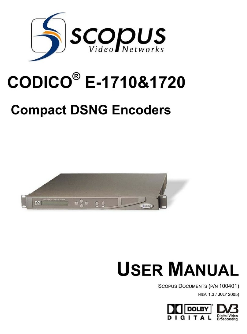
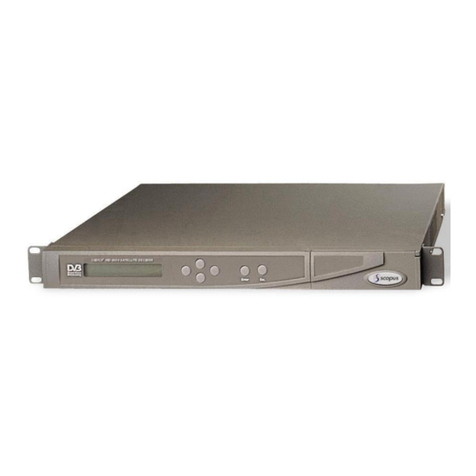
Scopus IRD-2900 Series User manual

IRD-2900 Series
Professional Integrated Receiver Decoders
U
SER
M
ANUAL
S
COPUS
D
OCUMENTS
(
P
/
N
100793)
(R
EV
.
4.6/
SW
V
1.80/
D
ECEMBER
2007)


IRD-2900 Series
Professional Integrated Receiver Decoders
IRD-2900 Series
Professional
Integrated Receiver Decoders
U
SER
M
ANUAL
S
COPUS
D
OCUMENTS
(
P
/
N
100793)
(R
EV
.
4.6/
SW
V
1.80/
D
ECEMBER
2007)


Scopus Video Networks Ltd.
International Headquarters
Scopus Video Networks Inc.
America
10 Ha’amal St., Park Afek
Rosh Ha’ayin, 4 092
Israel
3 Independence Way
Princeton, NJ 0 540.
USA
Tel: (972)-3-900-7777
Fax:(972)-3-900-7
Tel: (609)-9 7- 090
Fax:(609)-9 7- 095
Email:
Web:
www.scopus.net
Email:
Web:
www.scopususa.com
D
OCUMENT
ISTORY
V
ERSION
D
ATE
D
ETAILS
Rev. 1.0 April 2005 IRD-2900 v1.1
Rev. 1.4 June 2005 New features for SW v1.16
Rev. 2.0 August 2005 New features for SW v1.1
Rev. 2.5 January 2006 New features for SW v1.40
Rev. 2.6 March 2006 New features for SW v1.45
Rev. 2.7 March 2006 New features for SW v1.50
Rev. 3.0 June 2006 New features for SW v1.55
Rev. 4.0 September 2006 New features for SW v1.60
Rev 4.5 June 2007 New features for SW v1.70
Rev 4.6 December 2007 New features for SW v1. 0
©
2005 Scopus Video Networks Ltd. All rights reserved.
Scopus Video Networks Ltd. Reserves the rights to alter the equipment specifications and descriptions in this publication without
prior notice. No part of this publication shall be deemed to be part of any contract or warranty unless specifically incorporated by
reference into such contract or warranty.
The information contained herein is merely descriptive in nature, and does not constitute a binding offer for sale of the product
described herein.
File
IRD-2900 User Manual Rev 4.6.doc
. Saved
12/6/2007 1:11:00 PM

Page ii (Rev. 4.6/ SW v1. 0/ December 2007)

IRD-2900 Series
Professional Integrated Receiver Decoders
Scopus Documents (p/n 100793) Page i
INTRODUCTION
Scopus Video Networks Ltd. takes great pride in delivery of its products and
makes every endeavor to ensure its clients full satisfaction.
On behalf of the whole Scopus team, we would like to extend our
congratulations on your investment in the IRD-2900 Series of Professional
Integrated Receiver Decoders.
M
ANUAL
S
COPE
A
ND
S
TRUCTURE
This manual is comprised of the following main chapters:
1. OVERVIEW
An introduction and general description of the product, including
highlights, benefits & typical applications, functional & physical
descriptions, and main capabilities & specifications.
2. INSTALLATION
All the required procedures for installing and activating the unit. The
procedures include site preparation & requirements, installation in a 19"
rack, cable connections, rear panel options, pin-out descriptions, initial
settings, and the serviceability check.
3. CONTROL INTERFACES
Various control interfaces, common tools, screen or windows and
examples.
4. IRD-2900 OPERATION AND MANAGEMENT
The main section of this manual details screens and explaining every
function and each parameter.
5. APPENDICES
The appendices in this manual cover the issues of software upgrade,
aspect ratio configurations, warning massages, configuration file, and
installation procedures in German and French.

User Manual
Overview
Page ii (Rev. 4.6/ SW v1. 0/ December 2007)
T
ECHNICAL
S
UPPORT
In case of technical problems with the IRD-2900 components, refer to additional
system documentation. Usually, this may assist you to resolve technical
difficulties.
Call your local distributor for technical support if required.
R
ETURNIN
F
AULTY
P
ARTS
Before Returning an Item:
•Request an RMA (Return Merchandise Authorization) tracking number from
your local distributor.
•Scopus Video Networks Support will assign the number; this must
accompany the item being returned and is referred to in all correspondence.
•Send the item to Scopus Video Networks with the number included in the
accompanying documentation (shipping and customs forms).
C
USTOMER
S
UPPORT
P
OINT OF
C
ONTACT
(POC)
Scopus Video Networks Ltd.
International Headquarters
Scopus Video Networks Inc.
Americas
10 Ha’amal St., Park Afek
Rosh Ha’ayin, 4 092
Israel
100 Overlook Center Drive, 3rd Floor
Princeton, NJ 0 540.
USA
Tel: (972)-3-900-7777
Fax:(972)-3-900-7
Tel: (609)-9 7- 090
Fax:(609)-9 7- 095
Email:
Web:
www.scopus.net

IRD-2900 Series
Professional Integrated Receiver Decoders
Scopus Documents (p/n 100793) Page iii
W
ARRANTY
SCOPUS Video Networks Ltd. warrants that the product and any part thereof, including but
not limited to spare parts will, when properly installed, conform to SCOPUS Video Networks
Ltd. published specifications. Also, the product and any parts thereof, including but not limited
to spare parts, will be free from defects deriving from faulty workmanship and faulty materials
under standard use and service, for a period of twelve (12) months following the date of
manufacture thereof.
The supply of spare parts at a reasonable cost shall be available for a period of three (3) years
from the date of delivery.
This warranty does not cover ordinary wear and tear of the product or other defects due to
circumstances beyond SCOPUS Video Networks Ltd. control, such as: unsuitable operating
means, chemicals, electro-mechanical issues, or electrical influences and damages, which may
be caused by interference by the CUSTOMER or any unauthorized third party.
Defective cards and assemblies will be sent to SCOPUS Video Networks Ltd. for repair. The
repaired cards and assemblies will be returned to the CUSTOMER within 30 days from their
receipt by SCOPUS Video Networks Ltd.
Cards and assemblies repaired during the twelve (12) month warranty period will carry a
warranty of six (6) months from date of repair or until the end of original warranty period,
whichever is the later date.
SCOPUS Video Networks Ltd. sole liability under this warranty shall be limited to the repair or
replacement with equivalent units at SCOPUS Video Networks Ltd. facilities, of any product or
parts thereof that do not conform to SCOPUS Video Networks Ltd. published specifications or
that are defective in material or workmanship, as specified above. The expense of installing
repaired or replaced parts shall be borne by the CUSTOMER.
SCOPUS Video Networks Ltd. sole obligation under this warranty is to be the supplier of the
product to the CUSTOMER and to provide such services as set out in this warranty according
to the SCOPUS Video Networks Ltd. terms and conditions provided for herein. In no event will
SCOPUS Video Networks Ltd. be liable to the CUSTOMER for any: business expenses, loss of
profits, or incidental, indirect, or consequential damages, however caused, unless such
expenses, loss, or damages shall have derived from an infringement of patents of copyrights.
THE WARRANTIES STATED HEREIN ARE EXCLUSIVE AND ARE EXPRESSLY IN LIEU OF ALL
OTHER WARRANTIES, EXPRESSED OR IMPLIED, INCLUDING, BUT NOT LIMITED TO, THE
IMPLIED WARRANTY OF MERCHANTABILITY OR FITNESS FOR A PARTICULAR PURPOSE.
Beyond the warranty period, SCOPUS Video Networks Ltd. shall repair or replace defective
cards and assemblies according to its standard and relevant price list at such time. Cards and
assemblies thus repaired shall carry a warranty of six (6) months.
C
OMPLIANCE
EMC S
AFETY
EN55022 (CISPR 22) EN60950
EN55024 (CISPR 24) CB (IEC60950)
EN55013 (CISPR 13) UL60950
EN55020 (CISPR 20) cTUVus
FCC part 15 (class B)
CB

User Manual
Overview
Page iv (Rev. 4.6/ SW v1. 0/ December 2007)
CE
C
ERTIFICATION
The IRD-2900 meets all the CE Class A requirements.
In order to meet CE requirements, the following cables must be connected on all
ASI outputs (when applicable). When cables are connected to these outputs
then the device is compliant with the use of FAIR-RITE 0443164151.
FCC
C
OMPLIANCE
N
OTICE
These devices comply with Part 15 of the FCC Rules.
O
PERATION IS SUBJECT TO THE FOLLOWIN TWO CONDITIONS
:
•
These devices do not cause harmful interference.
•
These devices must accept any interference received, including
interference that may cause non relevant operation.
The FCC Wants You to Know
This equipment has been tested and found to comply with the limits for a
Class A digital device, pursuant to Part 15 of the FCC rules. These limits are
designed to provide reasonable protection against harmful interference when
the equipment is operated in a commercial environment.
This equipment generates, uses and can radiate radio frequency energy and,
if not installed and used in accordance with the instructions, may cause
harmful interference to radio communications.
Operation of this equipment in a residential area is likely to cause harmful
interference, in which case you will be required to correct the interference at
your expense.
FCC Warning
Modifications not expressly approved by the manufacturer could void your
authority to operate the equipment under FCC Rules.
Trade Name
Scopus
Product Name
Integrated Receiver Decoder
Product Model Number
IRD-2900 Series

IRD-2900 Series
Professional Integrated Receiver Decoders
Scopus Documents (p/n 100793) Page v
WEEE/ROHS COMPLIANCE POLICY
Scopus Video Networks Ltd. complies with the European Union's Directive
2002/96/EC as amended by Directive 2003/10 /EC, on Waste Electrical and
Electronic Equipment, also known as “WEEE.” Scopus understands all of its
products to fall under the WEEE Directive as IT and telecommunications
equipment.
Scopus will comply with the European Union's Directive 2002/95/EC on the
Restriction of use of Hazardous Substances, also known as “RoHS”, by July 01,
2006. All our products are either compliant or exempt from the RoHS Directive’s
lead-free requirements as far as the use of lead in solders for network
infrastructure equipment for switching, signaling, transmission as well as
network management for telecommunication, is concerned.
Scopus ensures that all products will either be re-used or recycled in compliance
with the WEEE Directive.
REEN
P
ROCUREMENT
P
OLICY
As part of its commitment to comply with global environmental initiatives,
Scopus will continue to actively work with its supply chain to ensure the ongoing
compliance with EU directives as well as the procurement and utilization of
reliable, environmentally responsible alternatives to hazardous substances.
WEEE
R
ECYCLIN
The EU has set up targets for the recovery of waste from electric and electronic
equipment (WEEE). In order to assist EU member states to preserve, protect
and improve the quality of the environment, protect human health and utilize
natural resources prudently and rationally, Scopus strives to recycle in
compliance with the WEEE Directive any of its products that cannot be re-used.
Scopus customers should:
•
Discard equipment in dedicated disposal areas only.
•
Arrange proper recycling of unneeded equipment, e.g. by re-using the
equipment or giving it away to charity.
•
For the take-back of Scopus equipment, customers must act in accordance
with the Scopus take-back policy, as provided in the website.

User Manual
Overview
Page vi (Rev. 4.6/ SW v1. 0/ December 2007)
TABLE OF CONTENTS
Chapter 1. Overview........................................................ 1-1
1.1.
General Information.......................................................... 1-1
1.2.
Highlights and Benefits...................................................... 1-2
1.3.
Applications ..................................................................... 1-3
1.4.
Functionality .................................................................... 1-4
1.5.
Mechanical Structure ........................................................ 1-5
1.5.1.
Front Panel ...................................................................... 1-5
1.5.2.
Various Front-Ends ........................................................... 1-6
1.5.3.
Software Permission (Licensing) ......................................... 1-7
1.5.4.
IRD-2900 models ............................................................. 1-
1.6.
Management...................................................................1-17
1.6.1.
Local Management...........................................................1-17
1.6.2.
Remote Management .......................................................1-17
1.7.
Characteristics and Specifications ......................................1-1
1.7.1.
Transport Stream Interface Options ...................................1-1
1.7.2.
Advanced Processing .......................................................1-21
1.7.3.
Decoder Outputs .............................................................1-22
1.7.4.
Conditional Access ...........................................................1-25
1.7.5.
Control and Monitoring.....................................................1-25
1.7.6.
Compliance.....................................................................1-26
1.7.7.
Environmental Conditions .................................................1-26
1.7. .
Physical and Power Specifications ......................................1-27
Chapter 2. Installation .................................................... 2-1
2.1.
Safety Precautions............................................................ 2-1
2.1.1.
Restricted Access Area ...................................................... 2-1
2.1.2.
Installation Codes............................................................. 2-1
2.2.
Inventory Check............................................................... 2-2
2.3.
Installation Instructions..................................................... 2-2
2.3.1.
Site Preparation ............................................................... 2-2
2.3.2.
Mechanical Rack Installation .............................................. 2-3
2.3.3.
Insertion of the DVB-CI Module (PCMCIA) ........................... 2-9
2.4.
Cable Connection.............................................................2-10
2.5.
Initialization And Configuration..........................................2-14
2.5.1.
Electrical Power Connection ..............................................2-14
2.5.2.
Powering Up ...................................................................2-16
2.5.3.
Tuning ...........................................................................2-16
2.5.4.
Performing Serviceability Check ........................................2-17
Chapter 3. IRD-2900 Control Interfaces.......................... 3-1
3.1.
Front Panel Control Interface ............................................. 3-1
3.1.1.
Controls and Displays........................................................ 3-1
3.1.2.
IRD-2900 Front Panel Screen Types.................................... 3-3

IRD-2900 Series
Professional Integrated Receiver Decoders
Scopus Documents (p/n 100793) Page vii
3.1.3.
IRD-2900 Menu Tree......................................................... 3-
3.1.4.
Front Panel Initialization Sequence ..................................... 3-9
3.2.
Web-Based Management Interface.................................... 3-11
3.2.1.
Controls and Displays...................................................... 3-12
3.2.2.
Initializing the Web-Based Management ............................ 3-17
Chapter 4. Operation and Management ...........................4-1
4.1.
Preset ............................................................................. 4-1
4.1.1.
Recall Preset .................................................................... 4-3
4.1.2.
Save Current Preset .......................................................... 4-4
4.1.3.
Rename Preset ................................................................. 4-
4.1.4.
Delete Preset ................................................................. 4-10
4.1.5.
Delete All Presets ........................................................... 4-12
4.2.
Configuration ................................................................. 4-13
4.2.1.
Receiver Modules............................................................ 4-14
4.2.2.
Satellite Receiver Modules ............................................... 4-15
4.2.3.
Stream Configuration Menu.............................................. 4-55
4.2.4.
Filtering......................................................................... 4-62
4.2.5.
Service Configuration Menu ............................................. 4-74
4.2.6.
Video Configuration Menu ................................................ 4-92
4.2.7.
Audio Configuration Menu ...............................................4-116
4.2. .
Data Configuration Menu ................................................4-126
4.2.9.
GenLock Configuration ...................................................4-137
4.2.10.
Conditional Access Configuration Menu.............................4-139
4.2.11.
Unit Configuration Menu .................................................4-14
4.3.
Status ..........................................................................4-170
4.3.1.
Receiver Status .............................................................4-171
4.3.2.
Stream Status Menu ......................................................4-177
4.3.3.
Service Status...............................................................4-1 0
4.3.4.
Video Status Menu.........................................................4-1 0
4.3.5.
Audio Status Menu.........................................................4-1 4
4.3.6.
Data Status Menu ..........................................................4-1 6
4.3.7.
GenLock Status .............................................................4-1
4.3. .
Conditional Access Status Menu.......................................4-1
4.3.9.
Unit Status Menu ...........................................................4-191
Appendix A Software Download ........................................A-1
A.1
Downloading Software Using FTP ........................................ A-1
A.1.1
Introduction..................................................................... A-1
A.1.2
Installation ...................................................................... A-1
A.2
Loading Software to the IRD-2900 through the Serial Port ..... A-6
A.2.1
PC Connection to the Serial Port ......................................... A-6
A.2.2
PC Serial-COM (Terminal) Software..................................... A-7
A.2.3
Opening Hyperterminal from MS Windows ........................... A-7
A.2.4
Defining the Communication .............................................. A-
A.2.5
Checking PC Terminal Communication with the IRD ............ A-10
A.2.6
Installation: ................................................................... A-11

User Manual
Overview
Page viii (Rev. 4.6/ SW v1. 0/ December 2007)
Appendix B IP-Front End Software Upgrade Procedure ....B-1
Appendix C Aspect Ratio Configuration Process................C-1
C.1
General ........................................................................... C-1
C.2
Aspect Ratio Conversion Machine........................................ C-1
C.3
Table of Conversions......................................................... C-3
Appendix D Configuration File...........................................D-1
D.1
Introduction..................................................................... D-1
D.2
Parameters ...................................................................... D-1
D.2.1
Stream Configurations ...................................................... D-1
D.2.2
Service Configurations ...................................................... D-2
D.2.3
Video Configurations ......................................................... D-3
D.2.4
Audio Configurations......................................................... D-4
D.2.5
Data Configurations .......................................................... D-4
D.2.6
DVB S Receiver Configurations ........................................... D-4
D.2.7
IP Receiver Configuration .................................................. D-5
Appendix E Warning Messages ......................................... E-1
E.1
General ........................................................................... E-1
E.2
Warning leds.................................................................... E-1
E.3
Warning messages ........................................................... E-2
Appendix F Installation (deutsch) .................................... F-1
F.1
Sicherheits-Vorsichtsmaßnahmen ........................................F-1
F.1.1
Bereich mit beschränktem Zugang.......................................F-1
F.2
Installations-Anweisungen ..................................................F-1
F.2.1
Vorbereitung des Aufstellungsplatzes ...................................F-2
F.2.2
Mechanische Installation des Gestells..................................F-2
F.2.3
Einfügen des DVB-CI -Moduls (PCMCIA) ...............................F-7
F.3
Kabel -Anschluss ...............................................................F-
F.4
Initialisierung und Konfiguration........................................F-13
F.4.1
Anschluss an die Energieversorgung ..................................F-13
F.4.2
Aufladen.........................................................................F-15
F.4.3
Abstimmung ...................................................................F-16
F.4.4
Durchführen der Nutzbarkeitsprüfung ................................F-16
Appendix Installation (française) .................................. -1
G.1
MESURES DE SECURITE .................................................... G-1
G.2
Liste d’inventaire .............................................................. G-1
G.3
Instructions d’Installation .................................................. G-2
G.3.1
Préparation de l’emplacement ............................................ G-2
G.3.2
Installation mécanique du rack........................................... G-3
G.3.3
Insertion du module DVB-CI (PCMCIA)................................ G-
G.4
Connexion par Cable ......................................................... G-
G.5
Initialisation et Configuration ........................................... G-13
G.5.1
Connection à l’alimentation électrique ............................... G-13
G.5.2
Démarrer ...................................................................... G-15
G.5.3
Réglage......................................................................... G-15

IRD-2900 Series
Professional Integrated Receiver Decoders
Scopus Documents (p/n 100793) Page ix
G.5.4
Effectuer une vérification de fonctionnement...................... G-16
LIST OF FI URES
Figure 1-1:
Signal Path in the IRD-2900 – Functionality Block Diagram ...... 1-4
Figure 1-2:
IRD-2900 Unit.................................................................... 1-5
Figure 1-3:
Front View of the IRD.......................................................... 1-5
Figure 1-4:
IRD-2961 Rear Panel (IP Input interface) .............................. 1-6
Figure 1-5:
IRD-2961 Rear Panel (DVB-S Dual Input interface) ................. 1-6
Figure 1-6:
IRD-2961 Rear Panel (Decoder Only interface) ....................... 1-7
Figure 1-7:
IRD-2960 Rear Panel (Standard) .......................................... 1-
Figure 1- :
IRD-2961 Rear Panel .......................................................... 1-9
Figure 1-9:
IRD-2962 Rear Panel .........................................................1-10
Figure 1-10:
IRD-2963 Rear Panel .........................................................1-11
Figure 1-11:
IRD-29 0 Rear Panel .........................................................1-12
Figure 1-12:
IRD-29 1 Rear Panel .........................................................1-13
Figure 1-13:
IRD-2990 Rear Panel .........................................................1-14
Figure 1-14:
IRD-2991 Rear Panel .........................................................1-15
Figure 1-15:
IRD-2992 Rear Panel .........................................................1-16
Figure 2-1:
Pair of Scopus Rack Slides ................................................... 2-4
Figure 2-2:
Scopus Rack Slide Measurement Specifications....................... 2-5
Figure 2-3:
Laying the Device on the Rack-Slides .................................... 2-6
Figure 2-4:
Clipped Mounting Brackets................................................... 2-6
Figure 2-5:
Device Mounted on a Pair of Rack-Slides ............................... 2-7
Figure 2-6:
Multiple Devices Mounted on a Single Pair of Rack-Slides......... 2-
Figure 2-7: DVB-CI Module................................................................... 2-9
Figure 2- :
IRD-2992 Rear Panel .........................................................2-10
Figure 2-9:
9-Pin Male Connector Pin Numbering....................................2-11
Figure 2-10:
Power Supply Configurations and Rack-Mount Grounding Jackscrew
.......................................................................................2-14
Figure 2-11:
DC Power Supply and Rack-Mount Grounding Jackscrew.........2-15
Figure 3-1:
Front Panel ........................................................................ 3-1
Figure 3-2:
IRD-2900 Front Panel Menu (Root Menu) - Basic Structure ...... 3-
Figure 3-3:
Web-Based Management Window – General View ..................3-11
Figure 3-4:
IRD-2900 Web-Based Management Interface Screen (Example)3-12
Figure 3-5:
Web-Based Management Title .............................................3-13
Figure 3-6:
Web-Based Management Menu and Sub-Menu Tabs...............3-14
Figure 3-7:
Status Menu .....................................................................3-14
Figure 3- :
Main-Menu Tabs ................................................................3-15
Figure 3-9:
Sub-Menu Tabs .................................................................3-15
Figure 3-10:
Edit-Value Parameter .........................................................3-16

User Manual
Overview
Page x (Rev. 4.6/ SW v1. 0/ December 2007)
Figure 3-11:
Select-Value Parameter......................................................3-16
Figure 3-12:
Refresh Button ..................................................................3-17
Figure 3-13:
IP Address Field ................................................................3-1
Figure 3-14:
IRD-2900 Web Management Access Box...............................3-19
Figure 4-1:
Web Interface Preset Screen.................................................4-2
Figure 4-2:
Web Interface Preset Recall Tab ............................................4-4
Figure 4-3:
Web Interface Save Preset Screen .........................................4-5
Figure 4-4:
Web Interface Save Tab .......................................................4-7
Figure 4-5:
Web Interface – Save Preset As New Name Tab ......................4-
Figure 4-6:
Web Interface Rename Preset Screen ....................................4-9
Figure 4-7:
Web Interface – Rename Preset Tab ......................................4-9
Figure 4- :
Web Interface Delete Preset Screen.....................................4-11
Figure 4-9:
Web Interface – Delete Preset Tab.......................................4-11
Figure 4-10:
IRD-2900 Configuration Main Menu .....................................4-13
Figure 4-11:
DVB-S Receiver Parameters Menu Screen.............................4-16
Figure 4-12:
DVB-S2 Receiver Parameters Menu Screen ...........................4-25
Figure 4-13:
DVB-DSNG Receiver Parameters Menu Screen ......................4-36
Figure 4-14:
DVB-IP Receiver – MPEGoIP 1 Parameters Menu Screen .........4-45
Figure 4-15:
DVB-IP Receiver – General Parameters Menu Screen .............4-51
Figure 4-16:
Stream Configuration Menu ................................................4-55
Figure 4-17:
Stream Parameters Menu Screen.........................................4-56
Figure 4-1 :
Filtering Parameters web-management screen ......................4-63
Figure 4-19:
General Filtering Parameters Menu Screen............................4-64
Figure 4-20:
Select Service Menu Screen ................................................4-6
Figure 4-21:
Select PIDs Menu Screen....................................................4-72
Figure 4-22:
Service Configuration Menu ................................................4-74
Figure 4-23:
TV1 Menu Screen ..............................................................4-77
Figure 4-24:
Preferred Language Screen.................................................4- 1
Figure 4-25:
PID Select Menu Screen .....................................................4- 5
Figure 4-26:
Port to Service Menu Screen ...............................................4-
Figure 4-27:
General Service Menu Screen..............................................4-90
Figure 4-2 :
Video Configuration Menu...................................................4-92
Figure 4-29:
Video 1 Menu Screen .........................................................4-95
Figure 4-30:
VBI 1 Parameters ............................................................ 4-102
Figure 4-31:
OSD1 Menu Screen.......................................................... 4-112
Figure 4-32:
Audio Configuration Menu................................................. 4-116
Figure 4-33:
Audio 1 Menu Screen ....................................................... 4-119
Figure 4-34:
Data Configuration Menu .................................................. 4-126
Figure 4-35:
IP Data Port Menu Screen................................................. 4-131
Figure 4-36:
Web Interface Genlock Screen .......................................... 4-137
Figure 4-37:
Conditional Access Configuration Menu............................... 4-139
Figure 4-3 :
Web Interface Conditional Access Screen............................ 4-140
Figure 4-39:
Web Interface Common Interface Screen ........................... 4-141

IRD-2900 Series
Professional Integrated Receiver Decoders
Scopus Documents (p/n 100793) Page xi
Figure 4-40:
Web Interface BISS Screen...............................................4-145
Figure 4-41:
Unit Configuration Menu ...................................................4-14
Figure 4-42:
Web Interface - Unit Screen..............................................4-149
Figure 4-43:
Soft Reset Web-Interface Screen .......................................4-151
Figure 4-44:
Change Password Screen..................................................4-151
Figure 4-45:
Control Password Screen ..................................................4-152
Figure 4-46:
Unit Serial Screen............................................................4-153
Figure 4-47:
Unit Ethernet Screen........................................................4-156
Figure 4-4 :
IRD-2900 Licensing Screen ...............................................4-15
Figure 4-49:
Alarms Web-Interface Screen............................................4-165
Figure 4-50:
GPI Web-Interface Screen ................................................4-166
Figure 4-51:
Web Interface – Traps Screen ...........................................4-167
Figure 4-52:
Add New Trap Destination.................................................4-169
Figure 4-53:
Delete Trap Destination ....................................................4-169
Figure 4-54:
Modify Trap Destination....................................................4-169
Figure 4-55:
IRD-2900 Status Screen ...................................................4-171
Figure 4-56:
IRD-2900 DVBS Status Screen ..........................................4-172
Figure 4-57:
IRD-2900 DVBS2 Status Screen ........................................4-174
Figure 4-5 :
IRD-2900 DVB IP Status Screen ........................................4-175
Figure 4-59:
IRD-2900 Stream Status Screen........................................4-177
Figure 4-60:
IRD-2900 Service Status Screen........................................4-1 0
Figure 4-61:
IRD-2900 Video Status Screen ..........................................4-1 1
Figure 4-62:
IRD-2900 Audio Status Screen ..........................................4-1 4
Figure 4-63:
IRD-2900 IP Data Port Status Screen .................................4-1 7
Figure 4-64:
IRD-2900 Unit Status Screen ............................................4-191
Figure 4-65:
Unit – Identity (Status Screen)..........................................4-192
Figure 4-66:
Unit – Versions (Status Screen).........................................4-192
Figure 4-67:
Unit – Monitoring (Status Screen).....................................4-193
Figure 4-6 :
Web-Management: Licensing ............................................4-195
Figure A-1:
Start Menu – Select Run ...................................................... A-2
Figure A-2:
Run Dialog Box................................................................... A-3
Figure A-3:
Open FTP Session ............................................................... A-3
Figure A-4:
Login to FTP....................................................................... A-4
Figure A-5:
Access Bin Folder................................................................ A-4
Figure A-6:
Loading the File.................................................................. A-5
Figure A-7:
Start Menu – Open HyperTerminal ........................................ A-
Figure A- :
HyperTerminal – Enter Connection........................................ A-9
Figure A-9:
Select PC COM Port............................................................. A-9
Figure A-10:
Port Settings Tab.............................................................. A-10
Figure A-11:
HyperTerminal Window...................................................... A-11
Figure A-12:
Update Software Version Command .................................... A-12
Figure A-13:
Erasing Flash Process ........................................................ A-13
Figure A-14:
Ready to Receive New Software ......................................... A-14

User Manual
Overview
Page xii (Rev. 4.6/ SW v1. 0/ December 2007)
Figure A-15:
Send File Dialog Box ..........................................................A-15
Figure A-16:
Sending Status Dialog Box..................................................A-15
Figure A-17:
IRD Boot Application Starts.................................................A-16
Figure A-1 :
Complete Software Loading ................................................A-17
Figure C-1:
Aspect Ratio Conversion Machine.......................................... C-2
Figure C-2:
Normal 4:3 Aspect Ratio...................................................... C-3
Figure C-3:
Normal 16:9 Aspect Ratio................................................... C-4
Figure E-1:
Front panel warning LEDs .....................................................E-1
Abbildung 1-2:
Paar Scopus- Gleitschienen..................................................F-3
Abbildung 1-3:
Maßspezifikationen der Scopus- Gleitschienen ........................F-4
Abbildung 1-4:
Auflegen des Geräts auf die Gleitschienen ..............................F-5
Abbildung 1-5:
Angeklemmte Montageträger ................................................F-5
Abbildung 1-6:
Auf einem Paar Gleitschienen montiertes Gerät .......................F-6
Abbildung 1-7:
Mehrfache auf einem einzigen Paar Gleitschienen montierte Geräte...................F-7
Abbildung 1- : DVB-CI -Modul ....................................................................F-
Abbildung 1-9:
IRD-2992- Tafel auf der Rückseite .........................................F-
Abbildung 1-10:
Nummerierung des 9 Stift-Verbindungssteckers .................... F-10
Abbildung 1-11:
Energieversorgungs-Konfigurationen und Gestellmontage-Erdungs-Schraubenwinde
(jackscrew).......................................................................... F-14
Abbildung 1-12:
Gleichstrom-Energieversorgung und Gestellmontage-Erdungsschraubenwinde
(Jackscrew) ......................................................................... F-15
Image G-1:
Paire de Rack Slides de Scopus ........................................... G-3
Figure G-2:
Spécifications de dimensions des rack-slides de Scopus........... G-4
Figure G-3:
poser l’appareil sur les Rack-Slides ....................................... G-5
Figure G-4:
Crochets d’assemblage attachés ........................................... G-5
Figure G-5:
Appareil monté sur une paire de Rack-Slides ......................... G-6
Figure G-6:
Plusieurs appareils montés sur une simple paire de Rack-Slides G-7
Figure G-7: DVB-CI Module................................................................... G-
Image G- :
Panneau arrière d’IRD-2992................................................. G-9
Figure G-9:
9-Pin connecteur male de numérotation des pins.................. G-10
Figure G-10:
Configuration d’alimentation électrique et vis de contact a la masse
de montage sur rack. ........................................................ G-14
Figure G-11:
Alimentation électrique DC et vis de contact à la masse ........ G-15

IRD-2900 Series
Professional Integrated Receiver Decoders
Scopus Documents (p/n 100793) Page xiii
LIST OF TABLES
Table 2-1:
IRD-2900 Rear Panel – Connectors and Cables......................2-10
Table 2-2:
RS-232/RS-4 5 Control Connector Pin-Out ...........................2-12
Table 2-3:
RS-232 Low Speed Data and GPI Pin-Out .............................2-12
Table 2-4:
RS-422 High Speed Data Pin-Out.........................................2-12
Table 2-5:
Audio 3-4 Breakout Cable Pin-Out (Scopus P/N 204346).........2-13
Table 2-6:
AES/EBU Balanced Breakout Cable Pin-Out (Scopus P/N 204345)2-13
Table 2-7:
IRD-2900 Serviceability Check ...........................................2-17
Table 4-1:
Band Frequency Range.......................................................4-17
Table 4-2:
Band Frequency Designations..............................................4-26
Table 4-3:
IRD-2900 Rear Panel – Connectors and Cables......................4-29
Table 4-3:
Band Frequency Range.......................................................4-37
Table C-1:
Table of Conversions - 4:3 Stream Option ............................. C-4
Table C-2:
Table of Conversions - 16:9 Options ..................................... C-6
Tabelle 1-3:
Hintere Tafel des IRD-2900 – Steckverbindungen und Kabel ...F-9
Tabelle 1-4:
Konfiguration und Funktion eines jeden Stiftes des RS-232/RS-4 5 -
Verbindungsstücks .................................................................F-11
Tabelle 1-5:
Konfigurationen und Funktion eines jeden Stiftes der RS-232-
Niedriggeschwindigkeitsdaten und der Graphikprozedur-Schnittstelle .........F-11
Tabelle 1-6:
RS-422 Konfigurationen und Funktion eines jeden Stiftes der
Hochgeschwindigkeitsdaten ................................................F-12
Tabelle 1-7:
Konfiguration und Funktion eines jeden Stiftes des Audio 3-4 –
Aufschlüsselungskabels (Scopus P/N 204346) .......................F-12
Tabelle 1- :
Konfiguration und die Funktion eines jeden Stiftes des
vorgesteuerten Aufschlüsselungskabels (Scopus P/N 204345)...F-12
Tabelle 1-9:
IRD-2900 –Nutzbarkeits-Prüfung .........................................F-16
Tableau G-1:
Panneau arrière d’IRD-2900 – Connecteurs et câbles .............. G-9
Tableau G-2:
RS-232/RS-4 5 Control Connector Pin-Out .......................... G-11
Tableau G-3:
RS-232 données a faible vitesse et GPI Pin-Out .................... G-11
Tableau G-4:
RS-422 Données de vitesse élevée Pin-Out .......................... G-12
Tableau G-5:
Pin-Out cable à fibre optique Audio 3-4 (Scopus P/N 204346) G-12
Tableau G-6:
AES/EBU pin-out de câbles à fibres optiques équilibrés (Scopus P/N
204345) ........................................................................... G-12
Tableau G-7:
IRD-2900 vérification de fonctionnement ............................ G-16
Table A-1:
RS-232 Control Cable Pin-to-Pin ........................................... A-6
Table A-2:
RS-4 5 Control Cable Pin-to-Pin Designations ........................ A-7

This manual suits for next models
9
Table of contents
Other Scopus Media Converter manuals

