Scopus UE-9000 User manual
UE-9000
Universal Encoder Platform
U
SER
M
ANUAL
S
COPUS
D
OCUMENTS
(P/N
100673)
(R
EV
.
3.0/
SW
V
2.0/
J
ANUARY
2
007)


UE-9000
Universal Encoder Platform
U
SER
M
ANUAL
S
COPUS
D
OCUMENTS
(P/N
100673)
(R
EV
.
3.0/
SW
V
2.0/
J
ANUARY
2007)


Scopus Video Networks Ltd.
International Headquarters
Scopus Video Networks Inc.
Americas
10 Ha’amal St., Park Afek
Rosh Ha’ayin, 4 092
Israel
3 Independence Way
Princeton, NJ 0 540
USA
Tel: (972)-3-900-7777
Fax: (972)-3-900-7
Tel: (609)-9 7- 090
Fax: (609)-9 7- 095
Email: info@scopus.net
Web: www.scopus.net
Email: info@scopususa.com
Web: www.scopususa.com
D
OCUMENT
H
ISTORY
V
ERSION
D
ATE
D
ETAILS
0.0 June 2004 Preliminary Publication
1.0 February 2006 Final Rev. 1.0 for UE-9210, 9217, and 921 . SW v1.14
1.2 March 2006 German Translation added in Ch. 2: Installation
1.5 June 2006 Features, Modules, and SW updates for SW v1.1
2.0 August 2006 SW updates for SW v1.20
3.0 January 2007 Features, Modules and SW update for SW v2.0
© 2007 Scopus Video Networks Ltd. All rights reserved.
Scopus Video Networks Ltd. Reserves the rights to alter the equipment specifications and descriptions in this publication without
prior notice. No part of this publication shall be deemed to be part of any contract or warranty unless specifically incorporated by
reference into such contract or warranty.
The information contained herein is merely descriptive in nature, and does not constitute a binding offer for sale of the product
detailed herein. Specifications and features sets are for technical information and are not legally biding.
UE-9000 is a registered trademark of Scopus Video Networks Ltd. in Israel, Germany, France, U.K. U.S.A. and Japan. All
references to registered trademarks of other vendors are the property of their respective owners.
File UE-9000 User Manual Rev. 3.0. Saved 1/1/2007 10:21:00 AM


UE-9000
Universal Encoder latform
Scopus Documents (P/N 100673) Page i
TABLE OF CONTENTS
Chapter 1. Overview ....................................................... 1 1
1.1.
Highlights and Options.......................................................1-2
1.2.
Applications .....................................................................1-3
1.2.1.
UE-94x0 – H.264 Encoding ................................................1-3
1.2.2.
UE-92x0 – MPEG-2 Multi Channel Encoder ...........................1-3
1.2.3.
UE-9217 – DVB-S or DSNG ................................................1-4
1.2.4.
UE-931 – DVB-S2 or DSNG ..............................................1-4
1.2.5.
Dual Pass Statistical Multiplexing ........................................1-5
1.2.6.
UE-9500 – Audio Only Unit.................................................1-5
1.2.7.
UE-9 x0 – HD H.264 Encoder.............................................1-5
1.3.
Management ....................................................................1-6
1.3.1.
Front Panel ......................................................................1-6
1.3.2.
Web-Based Management ...................................................1-6
1.3.3.
NMS-7000........................................................................1-6
1.4.
Mechanical Structure.........................................................1-7
1.4.1.
Front Panel ......................................................................1-7
1.4.2.
Rear Panel .......................................................................1-
1.5.
Model Options ................................................................ 1-11
1.5.1.
UE-9210 Interfaces and Features ...................................... 1-12
1.5.2.
UE-9220 Interfaces and Features ...................................... 1-13
1.5.3.
UE-9217 Interfaces and Features ...................................... 1-14
1.5.4.
UE-9310 Interfaces and Features ...................................... 1-15
1.5.5.
UE-931 Interfaces and Features ...................................... 1-16
1.5.6.
UE-9410 Interfaces and Features ...................................... 1-17
1.5.7.
UE-9500 Interfaces and Features ...................................... 1-1
1.6.
Characteristics and Capabilities......................................... 1-19
1.6.1.
Inputs ........................................................................... 1-19
1.6.2.
Outputs ......................................................................... 1-20
1.6.3.
Capabilities .................................................................... 1-22
1.6.4.
Control and Monitoring .................................................... 1-24
1.6.5.
BIT (Built In Tests) ......................................................... 1-24
1.6.6.
Power and Physical Specifications ..................................... 1-25
1.6.7.
Environment .................................................................. 1-26
1.6. .
Compliance .................................................................... 1-26
Chapter 2. Installation.................................................... 2 1
2.1.
Safety Precautions ............................................................2-1
2.2.
Inventory Check ...............................................................2-2
2.3.
Site Preparation................................................................2-3
2.4.
Mechanical Installation ......................................................2-4
2.4.1.
Installation in 19" Rack......................................................2-4
2.4.2.
Mechanical Rack Installation...............................................2-5

User Manual
Front Matter
Page ii (Rev. 3.0/ SW v2.0/ January 2007)
2.5.
Compact Flash Installation ................................................. 2-7
2.5.1.
Installation ...................................................................... 2-7
2.6.
Electrical Installation ......................................................... 2-
2.6.1.
Electrical Power Connections (AC or DC) .............................. 2-
2.7.
Initialization and Configuration ......................................... 2-10
2.7.1.
Powering Up................................................................... 2-10
2.7.2.
Initialization Sequence .................................................... 2-10
2.7.3.
Initial Configuration ........................................................ 2-11
Chapter 3. Control Interfaces ..........................................3 1
3.1.
Front Panel Control Interface.............................................. 3-1
3.1.1.
Controls and Displays........................................................ 3-2
3.1.2.
Screen Types ................................................................... 3-5
3.1.3.
Initializing the Front Panel ............................................... 3-11
3.2.
Web-Based Management Control Interface......................... 3-12
3.2.1.
Controls and Displays...................................................... 3-13
3.2.2.
Initializing the Web-Based Management ............................ 3-22
Chapter 4. Operation and Management ...........................4 1
4.1.
Saving Configuration......................................................... 4-2
4.1.1.
Front Panel Save Menu ...................................................... 4-3
4.1.2.
Web-Based Management Save Procedure............................. 4-4
4.2.
Root Menu ....................................................................... 4-5
4.2.1.
Front Panel Root Menu ...................................................... 4-6
4.2.2.
Web-Based Management Main Screen ................................. 4-
4.3.
Preset Menu ................................................................... 4-10
4.3.1.
Recall Menu ................................................................... 4-11
4.3.2.
Save Current Preset Menu................................................ 4-13
4.3.3.
Delete Menu................................................................... 4-1
4.3.4.
Rename Menu ................................................................ 4-20
4.4.
Modulation and Up-Converter Menu .................................. 4-23
4.4.1.
L-Band Modulator Parameters .......................................... 4-26
4.4.2.
IF Modulator Parameters.................................................. 4-31
4.4.3.
General Modulation Parameters ........................................ 4-34
4.5.
Configuration Menu ......................................................... 4-44
4.5.1.
Transport Stream Menu ................................................... 4-47
4.5.2.
Video Menu .................................................................... 4-70
4.5.3.
Audio Menu.................................................................... 4-70
4.5.4.
Output Interface Menu .................................................... 4-70
4.5.5.
Unit Menu ...................................................................... 4- 0
4.6.
Status Menu................................................................... 4- 1
4.6.1.
Service and PID Table ..................................................... 4- 3
4.6.2.
Unit Configurations and Permissions.................................. 4- 5
4.6.3.
Alarm Status .................................................................. 4- 7
4.6.4.
Access Authorization ....................................................... 4- 7
4.6.5.
Modulator Status ............................................................ 4-
Chapter 5. Service Configuration.....................................5 1

UE-9000
Universal Encoder latform
Scopus Documents (P/N 100673) Page iii
5.1.
Service List ......................................................................5-4
5.1.1.
Service Name ...................................................................5-6
5.1.2.
Service ID........................................................................5-6
5.1.3.
PMT PID...........................................................................5-7
5.1.4.
PCR PID...........................................................................5-7
5.1.5.
Scrambling Menu ..............................................................5-
5.1.6.
Add and Drop PID ........................................................... 5-11
5.2.
Add Service.................................................................... 5-15
5.2.1.
Add Service Menu (Front Panel)........................................ 5-15
5.2.2.
Add Service (Web-Management)....................................... 5-17
5.3.
Drop Service .................................................................. 5-1
5.3.1.
Drop Service Menu (Front Panel) ...................................... 5-1
5.3.2.
Drop Service (Web-Management) ..................................... 5-20
Chapter 6. Video Menu.................................................... 6 1
6.1.
Video Source Menu ...........................................................6-5
6.1.1.
Video Source ....................................................................6-6
6.1.2.
Video Format....................................................................6-7
6.1.3.
Video StatMux ..................................................................6-
6.1.4.
Video Test Pattern ............................................................6-9
6.1.5.
Aspect Ratio.....................................................................6-9
6.1.6.
VBI Menu....................................................................... 6-11
6.1.7.
Analog Interface Menu..................................................... 6-1
6.2.
MPEG-2 Configuration Menu ............................................. 6-25
6.2.1.
Dual Pass Parameters Menu ............................................. 6-27
6.2.2.
PID ............................................................................... 6-30
6.2.3.
Activation ...................................................................... 6-30
6.2.4.
Video Resolution ............................................................. 6-31
6.2.5.
Rate .............................................................................. 6-32
6.2.6.
Video Profile................................................................... 6-33
6.2.7.
Latency Control .............................................................. 6-34
6.2. .
Pre-Processing................................................................ 6-35
6.2.9.
MPEG-2 Advanced Menu .................................................. 6-36
6.3.
H.264 Configuration Menu................................................ 6-45
6.3.1.
PID ............................................................................... 6-46
6.3.2.
Activation ...................................................................... 6-47
6.3.3.
Video Resolution ............................................................. 6-47
6.3.4.
Rate .............................................................................. 6-49
6.3.5.
Display Scan .................................................................. 6-49
6.3.6.
Spatial Filter Strength ..................................................... 6-50
6.3.7.
Temporal Filter Strength .................................................. 6-51
6.3. .
H.264 Advanced Menu..................................................... 6-52
Chapter 7. Audio Menu.................................................... 7 1
7.1.
Musicam Configuration Menu ..............................................7-4
7.1.1.
PID .................................................................................7-6
7.1.2.
Activation ........................................................................7-6

User Manual
Front Matter
Page iv (Rev. 3.0/ SW v2.0/ January 2007)
7.1.3.
Coding Scheme ................................................................ 7-7
7.1.4.
Source ............................................................................ 7-
7.1.5.
Sample Rate .................................................................. 7-10
7.1.6.
Output Rate ................................................................... 7-11
7.1.7.
Encoding Mode ............................................................... 7-12
7.1. .
Test .............................................................................. 7-13
7.1.9.
Language....................................................................... 7-14
7.1.10.
Volume.......................................................................... 7-14
7.1.11.
Max Input Level.............................................................. 7-15
7.1.12.
Impedance..................................................................... 7-15
7.1.13.
A/V Delay Offset ............................................................. 7-16
7.1.14.
Advanced Menu .............................................................. 7-17
7.2.
Dolby Configuration Menu ................................................ 7-21
7.2.1.
PID ............................................................................... 7-23
7.2.2.
Activation ...................................................................... 7-23
7.2.3.
Coding Scheme .............................................................. 7-24
7.2.4.
Source .......................................................................... 7-25
7.2.5.
Sample Rate .................................................................. 7-27
7.2.6.
Output Rate ................................................................... 7-2
7.2.7.
Encoding Mode ............................................................... 7-29
7.2. .
Test .............................................................................. 7-30
7.2.9.
Language....................................................................... 7-30
7.2.10.
Volume.......................................................................... 7-31
7.2.11.
Max Input Level.............................................................. 7-32
7.2.12.
Impedance..................................................................... 7-33
7.2.13.
A/V Delay Offset ............................................................. 7-34
7.2.14.
Advanced Menu .............................................................. 7-35
7.2.15.
Pre-Processing Menu ....................................................... 7-43
7.3.
AAC\LC Configuration Menu ............................................. 7-47
7.3.1.
PID ............................................................................... 7-49
7.3.2.
Activation ...................................................................... 7-49
7.3.3.
Coding Scheme .............................................................. 7-50
7.3.4.
Source .......................................................................... 7-51
7.3.5.
Sample Rate .................................................................. 7-53
7.3.6.
Output Rate ................................................................... 7-54
7.3.7.
Encoding Mode ............................................................... 7-55
7.3. .
Test .............................................................................. 7-56
7.3.9.
Language....................................................................... 7-56
7.3.10.
Volume.......................................................................... 7-57
7.3.11.
Max Input Level.............................................................. 7-5
7.3.12.
Impedance..................................................................... 7-59
7.3.13.
A/V Delay Offset ............................................................. 7-60
7.4.
Audio Pass-Through Schemes........................................... 7-61
7.4.1.
Dolby AC-3 Pass-Through Menu........................................ 7-62
7.4.2.
Dolby-E Pass-Through Menu............................................. 7-75

UE-9000
Universal Encoder latform
Scopus Documents (P/N 100673) Page v
7.4.3.
Linear PCM Menu ............................................................ 7-
7.5.
Embedded Parameters Menu .......................................... 7-101
7.5.1.
Digital Video Source ...................................................... 7-103
7.5.2.
Group.......................................................................... 7-103
7.5.3.
Channel ....................................................................... 7-104
Chapter 8. Unit Menu ...................................................... 8 1
.1.
Licensing ......................................................................... -3
.1.1.
Device ID......................................................................... -4
.1.2.
License Key...................................................................... -5
.2.
Authorization Menu ........................................................... -6
.2.1.
User Identification............................................................. -6
.2.2.
Enter Code....................................................................... -6
.3.
System Menu ................................................................... -7
.3.1.
System Description ........................................................... -
.3.2.
System Up-Time ............................................................... -
.3.3.
System Contact ................................................................ -9
.3.4.
System Name................................................................... -9
.3.5.
System Location ............................................................. -10
.3.6.
Temperature .................................................................. -10
.4.
StatMux Server Parameters.............................................. -11
.4.1.
StatMux CMD IP ............................................................. -12
.4.2.
StatMux CMD Port........................................................... -12
.4.3.
StatMux Stat IP .............................................................. -13
.4.4.
StatMux Stat Port ........................................................... -13
.5.
Ethernet Port (Management) Menu.................................... -14
.5.1.
IP Address ..................................................................... -15
.5.2.
Subnet Mask .................................................................. -16
.5.3.
Default Gateway ............................................................. -17
.6.
SNMP Traps Menu ........................................................... -1
.6.1.
Traps Destination List...................................................... -19
.6.2.
Add Entry Menu (front-panel) ........................................... -23
.6.3.
Drop Entry Menu (front-panel).......................................... -24
.6.4.
Add and Drop Entries (web-management).......................... -25
.7.
System Clock ................................................................. -2
.7.1.
Source........................................................................... -30
. .
Serial Port (Management) Menu........................................ -31
. .1.
Baud Rate...................................................................... -32
.9.
Version Information Menu ................................................ -33
.9.1.
Encoder Serial Number .................................................... -33
.9.2.
Software Version Menu .................................................... -34
.9.3.
Hardware Version ........................................................... -34
.10.
Date/Time Menu ............................................................. -35
.10.1.
Set Time Menu ............................................................... -36
.11.
Alarm Configuration Menu................................................ -40
.11.1.
Alarm Setting Menu......................................................... -41

User Manual
Front Matter
Page vi (Rev. 3.0/ SW v2.0/ January 2007)
.12.
Display Contrast Menu..................................................... -43
.12.1.
Set Contrast................................................................... -43
Appendix A Software Download Using FTP .......................A 1
A.1
UE-9000 Setup IP .............................................................A-1
A.2
PC FTP Application ............................................................A-1
A.3
Download Preparations ......................................................A-2
A.4
Loading the Software through FTP ......................................A-2
A.4.1
Logon..............................................................................A-4
A.4.2
Delete Encoder's Database.................................................A-5
A.4.3
Loading the File ................................................................A-7
Appendix B Database Cloning ...........................................B 1
B.1
UE-9000 Setup IP .............................................................B-1
B.2
Download Preparations ......................................................B-1
B.3
PC FTP Application ............................................................B-1
B.4
Updating Database through FTP..........................................B-2
B.4.1
Logon..............................................................................B-4
B.4.2
Cloning the File ................................................................B-5
Appendix C Installation – German Translation..................C 1
C.1
Sicherheitsvorkehrungen ...................................................C-1
C.2
I Inventarprüfung .............................................................C-3
C.3
Vorbereitung des Standorts................................................C-4
C.4
Mechanischer Einbau.........................................................C-5
C.4.1
Einbau in das 19-Zoll-Rack.................................................C-5
C.4.2
Mechanischer Einbau in das Rack........................................C-6
C.5
Compact Flash-Installation.................................................C-
C.5.1
Installation ......................................................................C-
C.6
Elektrische Installation ......................................................C-9
C.6.1
Stromanschluss (Wechselstrom oder Gleichstrom) ................C-9
C.7
Initialisierung und Konfigurierung ..................................... C-11
C.7.1
Einschaltung .................................................................. C-11
C.7.2
Initialisierungssequenz .................................................... C-11
C.7.3
Erstkonfigurierung .......................................................... C-12
Appendix D Bit Rate Management and Related Dependency
Checks........................................................... D 1
D.1
Elementary Streams' Output Rate and Unit's Output Rate ......D-1
D.2
Adding an Elementary Stream ............................................D-2
D.2.1
Increase the TS Output Rate ..............................................D-3
D.2.2
Decrease Other ES Bit-Rate ...............................................D-3
Appendix E IP FEC Concept...............................................E 1
E.1
IP Stream Structure .......................................................... E-1
E.2
Stream Correction through Forward Error Correction ............. E-1

UE-9000
Universal Encoder latform
Scopus Documents (P/N 100673) Page vii
LIST OF FIGURES
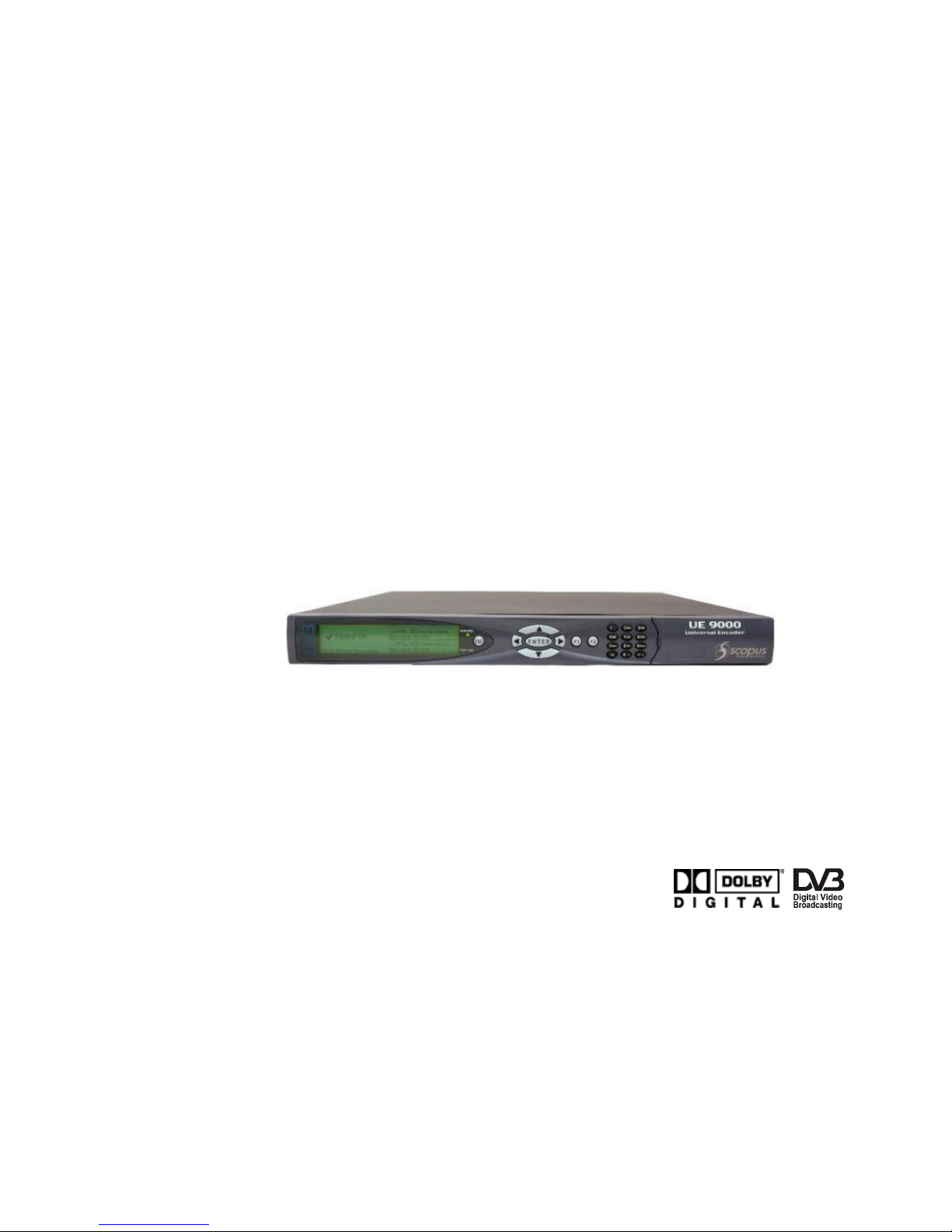
Figure 1-1:
UE-9000 Device.................................................................. 1-7
Figure 1-2:
Front View ......................................................................... 1-7
Figure 1-3:
UE-9210 Rear View ............................................................. 1-
Figure 1-4:
UE-9217 Rear View – DSNG Module ...................................... 1-9
Figure 1-5:
UE-9xx0 Rear View – IF Modulator ........................................ 1-9
Figure 1-6:
UE-9500 Rear View – Audio-Only Module ............................. 1-10
Figure 2-1:
Rack Mount Slides............................................................... 2-5
Figure 2-2:
Encoders Mounted in a Single Rack ....................................... 2-6
Figure 2-3:
Compact Flash Drive ........................................................... 2-7
Figure 2-4:
Power Supply Jack Screw Ground Connection ......................... 2-9
Figure 2-5:
Ethernet Cable Connection ................................................... 2-11
Figure 3-1:
Front Panel ........................................................................ 3-2
Figure 3-2:
Alphanumeric Touch Pad...................................................... 3-3
Figure 3-3:
Menu Navigation Screen Example ......................................... 3-6
Figure 3-4:
Edit Menu Screen Example................................................... 3-7
Figure 3-5:
Table Menu Screen Example................................................. 3-
Figure 3-6:
Edit Value Screen Example................................................... 3-9
Figure 3-7:
Select Value Screen Example................................................ 3-10
Figure 3- :
Web-Based Management Window – General View ................. 3-12
Figure 3-9:
Web-Based Management Window – Status and Configuration
Sections .......................................................................... 3-13
Figure 3-10:
Web-Based Management Title ............................................ 3-14
Figure 3-11:
Web-Based Management Title ............................................ 3-14
Figure 3-12:
Status Menu..................................................................... 3-17
Figure 3-13:
'Save' Bar ........................................................................ 3-17
Figure 3-14:
Main-Menu Tabs ............................................................... 3-1
Figure 3-15:
Sub-Menu Tabs................................................................. 3-1
Figure 3-16:
Sub-Menu Hyperlink.......................................................... 3-19
Figure 3-17:
Dynamic Hyperlinks' List .................................................... 3-19
Figure 3-1 :
Edit-Value Parameter ........................................................ 3-20
Figure 3-19:
Select-Value Parameter ..................................................... 3-20
Figure 3-20:
Save Changes Button ........................................................ 3-21
Figure 3-21:
Drop Changes Button ........................................................ 3-21
Figure 3-22:
Refresh Button ................................................................. 3-21
Figure 3-23:
IP Address Field................................................................ 3-24
Figure 4-1:
"Save Changes" and "Drop Changes" Buttons......................... 4-4
Figure 4-2:
Saving Confirmation Message............................................... 4-4
Figure 4-3:
Dropping Confirmation Message............................................ 4-5
Figure 4-4:
UE-9000 Root Menu Tree ..................................................... 4-7

User Manual
Front Matter
Page viii (Rev. 3.0/ SW v2.0/ January 2007)
Figure 4-5:
Web-Based Management Display – Main Menu ....................... 4-
Figure 4-6:
Web-Based Management Main Menu Tree Structure ................ 4-9
Figure 4-7:
Preset Menu Tree.............................................................. 4-10
Figure 4- :
Recall Preset Menu Display................................................. 4-11
Figure 4-9:
Save Preset Menu Display .................................................. 4-13
Figure 4-10:
Override Existing Preset Menu Display................................. 4-14
Figure 4-11:
Specify Preset Name Menu Display...................................... 4-16
Figure 4-12:
Delete Preset Menu Display................................................ 4-1
Figure 4-13:
Rename Preset Menu Display ............................................. 4-20
Figure 4-14:
Configuration Menu Tree.................................................... 4-45
Figure 4-15:
Transport Menu – Sub Tabs (General Menu Display).............. 4-4
Figure 4-16:
Transport Menu – Web-Management Tree Structure.............. 4-49
Figure 4-17:
Cascading Menu Display .................................................... 4-54
Figure 4-1 :
Scrambling Menu Display ................................................... 4-56
Figure 4-19:
Clear Scrambling Menu Display........................................... 4-57
Figure 4-20:
BISS-1 Scrambling Menu Display ........................................ 4-59
Figure 4-21:
BISS-E Buried ID Scrambling Menu Display.......................... 4-61
Figure 4-22:
BISS-E Injected ID Scrambling Menu Display ....................... 4-63
Figure 4-23:
SI Tables Menu Display ..................................................... 4-65
Figure 4-24:
IP Out Menu Display.......................................................... 4-72
Figure 4-25:
Status Menu Tree ............................................................. 4- 1
Figure 4-26:
Status Section.................................................................. 4- 2
Figure 4-27:
Services and PIDs Table Display ......................................... 4- 4
Figure 4-2 :
Services and PIDs Table Display ......................................... 4- 6
Figure 4-29:
Alarms List Display ........................................................... 4- 7
Figure 4-30:
L-Band Modulator Status Display ........................................ 4-
Figure 4-31:
IF Modulator Status Display ............................................... 4-
Figure 5-1:
Service Configuration Menu Tree Structure (According to Front
Panel) ............................................................................... 5-2
Figure 5-2:
Services Menu Display......................................................... 5-3
Figure 5-3:
Service List Display............................................................. 5-4
Figure 5-4:
Service Configuration Menu – First Service Selected................ 5-5
Figure 5-5:
Scrambling Menu Display ..................................................... 5-
Figure 5-6:
Scrambling Activation Field Display ..................................... 5-10
Figure 5-7:
PID List Table Display........................................................ 5-14
Figure 5- :
Services Menu Display – Add Service .................................. 5-17
Figure 5-9:
Services Menu Display – Drop Service ................................. 5-20
Figure 6-1:
Video Parameters Menu Display – Video 1 Selected ................. 6-3
Figure 6-2:
Video Menu Tree Structure................................................... 6-4
Figure 6-3:
Video Source Menu Display .................................................. 6-5
Figure 6-4:
VBI Lines Menu Display ..................................................... 6-13
Figure 6-5:
Select VBI Lines Value....................................................... 6-14

UE-9000
Universal Encoder latform
Scopus Documents (P/N 100673) Page ix
Figure 6-6:
VBI Bit-Rate Calculation Formula ........................................ 6-16
Figure 6-7:
Analog Interface Section Display......................................... 6-19
Figure 6- :
MPEG2 Parameters Menu ................................................... 6-26
Figure 6-9:
Dual Pass Parameters Menu ............................................... 6-2
Figure 6-10:
MPEG2 Advanced Parameters Menu..................................... 6-36
Figure 6-11:
H.264 Configuration Menu.................................................. 6-46
Figure 6-12:
H.264 Advanced Parameters Menu ...................................... 6-52
Figure 7-1:
Audio Configuration Menu Tree Structure (Divided into Coding
Schemes) .......................................................................... 7-2
Figure 7-2:
Musicam Configuration Menu Display – Aud1 Selected ............. 7-5
Figure 7-3:
Musicam Advanced Menu Display ........................................ 7-17
Figure 7-4:
Dolby Configuration Menu Display – Aud1 Selected ............... 7-22
Figure 7-5:
Dolby Advanced Menu Display ............................................ 7-35
Figure 7-6:
Dolby Pre-Processing Menu Display ..................................... 7-43
Figure 7-7:
AAC\LC Configuration Menu Display – Aud1 Selected............. 7-4
Figure 7- :
UE-9000 Clock Interface Synchronization............................. 7-61
Figure 7-9:
Dolby AC-3 Pass-Through Configuration Menu – Aud1 Selected7-63
Figure 7-10:
Dolby-E Pass-Through Configuration Menu – Aud1 Selected ... 7-76
Figure 7-11:
Linear PCM Configuration Menu – Aud1 Selected................... 7- 9
Figure 7-12:
Embedded Parameters Section Display ...............................7-101
Figure 7-13:
Embedded Audio Source ...................................................7-102
Figure -1:
Unit Menu Tree Structure..................................................... -1
Figure -2:
Licensing Menu Display........................................................ -3
Figure -3:
System Menu Display .......................................................... -7
Figure -4:
StatMux Menu Display ....................................................... -11
Figure -5:
Management (Ethernet Port) Menu Display .......................... -14
Figure -6:
SNMP Traps List Display..................................................... -19
Figure -7:
Trap Configuration Menu Display......................................... -20
Figure - :
"Add New" Button ............................................................. -25
Figure -9:
Select an Entry ................................................................. -26
Figure -10:
Delete Button ................................................................... -27
Figure -11:
External-Clock Mechanism Illustration ................................. -2
Figure -12:
Clock Menu Display ........................................................... -29
Figure -13:
Serial Port Menu Display .................................................... -31
Figure -14:
Version Menu Display ........................................................ -33
Figure -15:
Version Menu Display ........................................................ -34
Figure -16:
Date Menu Display ............................................................ -35
Figure -17:
Alarm Menu Display .......................................................... -41
Figure -1 :
Alarm Severity Parameter Display....................................... -42
Figure A-1:
Start MenuRun................................................................. A-2
Figure A-2:
'Run' Dialog Box .................................................................A-3
Figure A-3:
FTP Session Display ............................................................A-3

User Manual
Front Matter
Page x (Rev. 3.0/ SW v2.0/ January 2007)
Figure A-4:
FTP Session Display – Username and Password ...................... A-4
Figure A-5:
FTP Session Display – Bin .................................................... A-4
Figure A-6:
FTP Session Display – CD Config and LS Folders ..................... A-5
Figure A-7:
FTP Session Display – Database Files .................................... A-6
Figure A- :
FTP Session Display – Remove Database Files ........................ A-6
Figure A-9:
FTP Session Display – File Location ....................................... A-7
Figure A-10:
FTP Session Display – Software Download Complete ............... A-
Figure B-1:
Start MenuRun................................................................. B-2
Figure B-2:
Run Dialog Box................................................................... B-3
Figure B-3:
FTP Session Display ............................................................ B-3
Figure B-4:
FTP Session Display – Username and Password ...................... B-4
Figure B-5:
FTP Session Display – Bin .................................................... B-4
Figure B-6:
FTP Session Display – File Location ....................................... B-5
Figure B-7:
FTP Session Display – Software Download Complete ............... B-6
Abbildung C-1:
Gestellaufsatzschiene .......................................................... C-6
Abbildung C-2:
Encoder, die in ein einzelnes Rack eingebaut sind .................. C-7
Abbildung C-3:
Compact Flash-Treiber........................................................ C-
Abbildung C-4:
Netzversorgung Abdrückschraube (Ground Jackscrew) zum
Erdungsanschluss ............................................................. C-10
Figure D-1:
Adding a New Elementary Stream.........................................D-2
Figure D-2:
Bit-Rate Consumption Calculation Formula.............................D-2

UE-9000
Universal Encoder latform
Scopus Documents (P/N 100673) Page xi
LIST OF TABLES
Table 1-1:
UE-9000 User Manual Terms and Abbreviations .......................xiii
Table 6-1:
VBI Lines Available Values ................................................. 6-14
Table 6-2:
Automatic Resolution Values .............................................. 6-32
Table 6-3:
Automatic Resolution Values .............................................. 6-4
Table 7-1:
Channel #1 Source Vs. Channel #2 Source ............................ 7-9
Table 7-2:
Channel #2 Source Vs. Channel #1 Source ............................ 7-9
Table 7-3:
Available Musicam Output Rate Options ............................... 7-12
Table 7-4:
Channel #1 Source Vs. Channel #2 Source .......................... 7-26
Table 7-5:
Channel #2 Source Vs. Channel #1 Source .......................... 7-26
Table 7-6:
Available Dolby Output Rate Options ................................... 7-29
Table 7-7:
Channel #1 Source Vs. Channel #2 Source .......................... 7-52
Table 7- :
Channel #2 Source Vs. Channel #1 Source .......................... 7-52
Table 7-9:
Available AAC\LC Output Rate Options................................. 7-55
Table 7-10:
Channel #1 Source Vs. Channel #2 Source .......................... 7-67
Table 7-11:
Channel #2 Source Vs. Channel #1 Source .......................... 7-67
Table 7-12:
Available Dolby AC-3 Output Rate Options ........................... 7-70
Table 7-13:
Channel #1 Source Vs. Channel #2 Source .......................... 7- 0
Table 7-14:
Channel #2 Source Vs. Channel #1 Source .......................... 7- 0
Table 7-15:
Channel #1 Source Vs. Channel #2 Source .......................... 7-93
Table 7-16:
Channel #2 Source Vs. Channel #1 Source .......................... 7-93

User Manual
Front Matter
Page xii (Rev. 3.0/ SW v2.0/ January 2007)
INTRODUCTION
Scopus Video Networks Ltd. takes great pride in delivery of its products and
makes every endeavor to ensure your full satisfaction.
On behalf of the whole Scopus team, we would like to extend our
congratulations on your investment in the UE-9000 Series of Universal Encoders.
M
ANUAL
S
COPE
A
ND
S
TRUCTURE
The UE-9000 Universal Encoder User manual is comprised of the following
chapters:
1. O
VERVIEW
This chapter provides the introduction and product description, including:
•Highlights and Benefits
•Applications
•Management
•Mechanical Structure
•Model Options
•Characteristics and Specifications
2. I
NSTALLATION
This chapter provides information and procedures required to install and
activate the unit. These procedures include:
•Inventory Check
•Site Preparation
•Installation in 19" Rack
•Mechanical Rack Installation
•Compact Flash Installation
•Electrical Installation
•Initialization and Configuration
3. C
ONTROL
I
NTERFACES
This chapter details the main control interfaces, such as UE front panel and
web-management interface, as well as their operation, interface, and so on.
4. O
PERATION AND
M
ANAGEMENT
This chapter and all proceeding chapters detail unit operation including
control and monitoring functional capabilities.

UE-9000
Universal Encoder latform
Scopus Documents (P/N 100673) Page xiii
T
ERMS AND
A
BBREVIATIONS
Table 1-1: UE-9000 User Manual Terms and Abbreviations
T
ERM
D
ESCRI TION
T
ERM
D
ESCRI TION
ASI
Asynchronous Serial Interface
AT
Program Association Table
ATSC
Advanced Television Systems
Committee
CM
Pulse Code Modulation
C/V
Composite Video interface
CR
Program Clock Reference
CA
Conditional Access
ID
Packet Identifier
CAS
Conditional Access System
MT
Program Mapping Table
CAT
Conditional Access Table
S TS
Single-Protocol Transport Stream
CBR
Constant Bit-Rate
SI
Program Specific Information
CF
Compact Flash (card)
SI
Service Information
DJ
De-Jitter, De-Jittering
TBC
Time Base Corrector
DVB
Digital Video Broadcast
TS
Transport Stream
ECM
Entitlement Management
Message
UCM
Up-Converter Modulator
EMM
Entitlement Control Message
UE
Universal Encoder
ES
Elementary Stream, also called
Stream Element
VBR
Variable Bit-Rate
M EG
Motion Picture Expert Group

User Manual
Front Matter
Page xiv (Rev. 3.0/ SW v2.0/ January 2007)
T
ECHNICAL
S
UPPORT
In case of technical problems with the encoder components, refer to the system
documentation. This will assist you in resolving most technical difficulties.
Call your local distributor for technical support if required.
R
ETURNING
F
AULTY
P
ARTS
Before Returning an Item:
•Request an RMA (Return Merchandise Authorization) tracking number from
your local distributor.
•Scopus Video Networks Support will assign an RMA number; this must
accompany the item being returned and will be referred to in all
correspondence.
•Send the item to Scopus Video Networks with number included in the
accompanying documentation (shipping and customs forms).
Customer Support Contact Information
Scopus Video Networks Ltd.
International Headquarters
Scopus Video Networks Inc.
Americas
10 Ha’amal St., Park Afek
Rosh Ha’ayin, 4 092
Israel
3 Independence Way
Princeton, NJ 0 540
USA
Tel: (972)-3-900-7777
Fax: (972)-3-900-7
Tel: (609)-9 7- 090
Fax: (609)-9 7- 095
Email: support@scopus.net
Web: www.scopus.net
Table of contents
Other Scopus Media Converter manuals


Popular Media Converter manuals by other brands


Clarion
Clarion DVH940N owner's manual

Euromag
Euromag MC608 Series instruction manual
 user guide")
Transition Networks
Transition Networks E-PSW-FX-03(LH) user guide

Transition Networks
Transition Networks SSDTF1011-100 user guide

Neteon
Neteon EF23-1-Fm-SC-2 Hardware installation guide

Digitus
Digitus DS-40201 user manual


