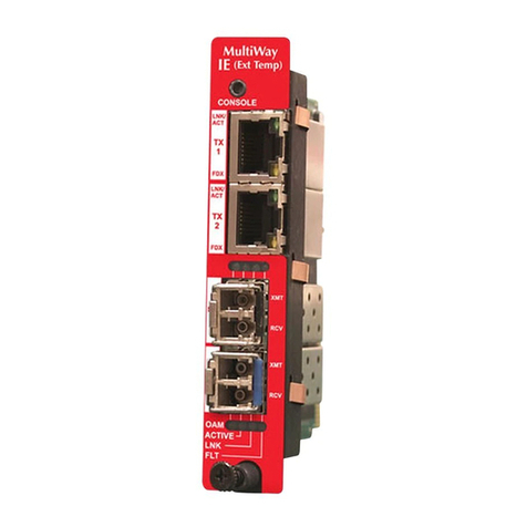
Scopus CODICO IRD-2600 User manual

CODICO® IRD-2600 / IRD-2800
INTEGRATED RECEIVER DECODERS
User Manual
P/N 2349-72784-00
(Rev. B / December 2001)

Scopus Network Technologies Inc.
U.S. Offices
Scopus Network Technologies Ltd.
International Headquarters
12265 World Trade Drive
Suite G
San Diego, CA 92128
10 Ha’amal St., Park Afek
Rosh Ha’ayin, 48092
Israel
Tel: (858) 618-1600
Fax: (858) 618-1615
Tel: (972) –3-9007777
Fax: (972) –3-9007888
Email: [email protected]
Web: www.scopus.net
© 2001 Scopus Network Technologies Ltd. All rights reserved.
Scopus Network Technologies Ltd. Reserves the rights to alter the equipment specifications and
descriptions in this publication without prior notice. No part of this publication shall be deemed to be part
of any contract or warranty unless specifically incorporated by reference into such contract or warranty.
The information contained herein is merely descriptive in nature, and does not constitute a binding offer
for sale of the product described herein.
CODICO® is a Registered trademark of Scopus Network Technologies Ltd. In Israel, Germany, France,
U.K. U.S.A. and Japan. All references to registered trademarks of other vendors are the property of their
respective owners.
File IRD 2600-2800 User Rev B Draft.doc Saved 17/03/02 16:26

IRD-2600 / IRD-2800
Integrated Receiver Decoders
P/N 2349-72784-00 Page i
INTRODUCTION
Scopus Network Technologies Ltd. takes great pride in delivery of its products, and makes
every endeavor to ensure its clients full satisfactory.
On behalf of all the Scopus team, we would like to extend our congratulations on your
investment in the CODICO IRD-2600 and IRD-2800 Family of Integrated Receiver
Decoders.
IRD-2600 AND IRD-2800 INTEGRATED RECEIVER DECODER
MANUAL SCOPE AND STRUCTURE
The User Manual for the CODICO® IRD-2600 and IRD-2800 Integrated Receiver Decoders is
comprised of three main sections:
OVERVIEW:
This section provides introduction and product description, including highlights, benefits
and typical applications, gives a functional and physical description of the unit and lists its
main capabilities and specifications.
INSTALLATION:
This section provides data and procedures required to install and activate the unit.
Procedures include site preparation and requirements, installation in a 19" rack, cable
connections, panel options and Pin-out descriptions, initial settings and serviceability
check.
OPERATION:
This section provides theoretical background on the operation of the unit, and gives data
and instructions on using the unit and operating the control and monitoring functions
provided to the user.
MAINTENACE
The manual includes the following appendices:
• Appendix A Operational Menu Trees.
• Appendix B LNB Theory Of Operation.
It is assumed throughout this document that personnel have a general knowledge about the
IRD-2600 and IRD-2800 Integrated Receiver Decoders, application and capabilities.
General knowledge of the CODICO® System and its application is also assumed. For detailed
information, refer to the CODICO® MPEG-2 DVB Family Product Description documents.

User Manual
Front Matter
Page ii P/N 2349-72784-00
TECHNICAL SUPPORT
In case of technical problems with the CODICO system or one of its’ components please
refer to the System Documentation. In most instances, this may save you time in resolving
technical difficulties.
Should you not be able to resolve the problem please call your local distributor for technical
support.
HOW TO RETURN FAULTY PARTS
Before returning an item:
1. Request a RMA (Return Merchandise Authorisation) Tracking Number from your local
Distributor.
2. Scopus Network Technologies Support will assign a RMA Tracking Number; this must
accompany the item being returned and will be referred to in all correspondence.
3. The item is sent to Scopus Network Technologies with the RMA Number included in the
accompanying documentation (shipping and customs forms).
Customer Support Point Of Contact (POC)
Scopus Network Technologies Inc.
U.S. OFFICES
Scopus Network Technologies Ltd.
INTERNATIONAL HEADQUARTERS
12265 World Trade Drive 10 Ha’amal St., Park Afek
Suite G Rosh Ha’ayin, 48092
San Diego, CA 92128 Israel
Tel: (858) 618-1600 Tel: (972) –3-9007777
Fax: (858) 618-1615 Fax: (972) –3-9007888
Email: info@scopususa.com Email: info@scopus.co.il
Web: www.scopususa.com Web: www.scopus.co.il

IRD-2600 / IRD-2800
Integrated Receiver Decoders
P/N 2349-72784-00 Page iii
WARRANTY
SCOPUS Network Technologies Ltd. warrants that the Product and any part thereof,
including, but not limited to spare parts, will, when properly installed, conform to SCOPUS
Network Technologies Ltd. published specifications and that the Product and any parts
thereof, including, but not limited to, spare parts, will be free from defects deriving from wrong
workmanship and faulty materials under normal use and service, for a period of twelve (12)
months following the date of manufacture thereof.
The supply of spare parts at reasonable cost shall be available for a period of three (3) years
from the date of delivery.
This warranty does not cover ordinary wear and tear of the Product or other defects due to
circumstances beyond SCOPUS Network Technologies Ltd. control such as unsuitable
operating means, chemical, Electro-mechanical or electrical influences and damages which
may be caused by interference by the CUSTOMER or any unauthorized third party.
Defective cards/assemblies will be sent to SCOPUS Network Technologies Ltd. for repair.
The repaired cards/assemblies will be returned to the CUSTOMER within 30 days from their
receipt by SCOPUS Network Technologies Ltd.
Cards/assemblies repaired during the 12 months warranty period will carry a warranty of 6
months from date of repair or until end of original warranty period, whichever is the later date.
SCOPUS Network Technologies Ltd. sole liability under this warranty shall be limited to the
repair or replacement with equivalent units at SCOPUS Network Technologies Ltd. facilities,
of any Product or parts thereof that do not conform to SCOPUS Network Technologies Ltd.
published specifications or that are defective in material or workmanship, as specified above.
The expense of installing repaired or replaced parts shall be borne by the CUSTOMER.
SCOPUS Network Technologies Ltd. sole obligation under this Warranty is be the supplier of
the Product to the CUSTOMER and to provide such services as set out in this Warranty on
the SCOPUS Network Technologies Ltd. terms and conditions provided for herein. In no
event will SCOPUS Network Technologies Ltd. be liable to the CUSTOMER for any business
expenses, loss of profits, incidental, indirect or consequential damages, however caused,
unless such expenses, loss or damages shall have derived from an infringement of patents of
copyrights.
THE WARRANTIES STATED HEREIN ARE EXCLUSIVE AND ARE EXPRESSLY IN LIEU
OF ALL OTHER WARRANTIES, EXPRESSED OR IMPLIED, INCLUDING, BUT NOT
LIMITED TO, THE IMPLIED WARRANTY OF MERCHANTABILITY OR FITNESS FOR A
PARTICULAR PURPOSE.
Beyond the warranty period, SCOPUS Network Technologies Ltd. shall repair or replace
defective cards/assemblies according to its standard price list relevant at such time.
Cards/assemblies thus repaired shall carry a warranty of 6 months.
CE Certification
Both IRD-2600 and IRD-2800 meet all the CE Class B requirements with the exception of
Emission Requirements.
In order to meet CE requirements, the following cables must be connected on all ASI outputs
(ASI out 1, ASI out 2, ASI out 3). When cables are connected to these outputs then the
device is compliant with FAIR-RITE 0443164151.

User Manual
Front Matter
Page iv P/N 2349-72784-00
FCC Compliance Notice
Trade Name Scopus
Product Name Integrated Receiver Decoder
Product Model Number CODICO® IRD-2600
Product Model Number CODICO® IRD-2800
These devices comply with Part 15 of the FCC Rules.
Operation is subject to the following two conditions:
1. This device may not cause harmful interference.
2. This device must accept any interference received, including interference that may cause
undesired operation.
Responsible Party:
Responsible Party's Name Jay Gedanken
Address 16776 Bernardo Ctr. Dr.,
San Diego, CA 92128
Responsible Party's Telephone 1-619-618-1600
The FCC Wants You to Know
This equipment has been tested and found to comply with the limits for a Class B digital
device, pursuant to Part 15 of the FCC rules. These limits are designed to Provide
reasonable protection against harmful interference in a residential installation. This
equipment generates, uses and can radiate radio frequency energy and, If not installed and
used in accordance with the instructions, may cause harmful interference to radio
communications.
However, there is no guarantee that interference will not occur in a particular installation. If
this equipment does cause harmful interference to radio or television reception, which can
be determined by turning the equipment off end on, the user is encouraged to try to correct
the interference by one or more of the following measures:
Reorient or relocate the receiving antenna.
Increase the separation between the equipment and receiver.
Connect the equipment to an outlet on a circuit different from that to which the receiver is
connected.
Consult the dealer or an experienced radio/TV technician.
FCC Warning
Modifications not expressly approved by the manufacturer could void the user authority to
operate the equipment under FCC Rules.

IRD-2600 / IRD-2800
Integrated Receiver Decoders
P/N 2349-72784-00 Page v
TABLE OF CONTENTS
LIST OF FIGURES ................................................................................................................................ viii
LIST OF TABLES..................................................................................................................................... x
1. Overview .................................................................................................................................. 1-1
1.1. General Information.................................................................................................. 1-1
1.1.1. Highlights and Benefits ............................................................................. 1-1
1.1.1.1. Inputs....................................................................................... 1-2
1.1.1.2. Outputs.................................................................................... 1-3
1.1.1.3. Conditional Access.................................................................. 1-4
1.1.1.4. Control And Monitoring ........................................................... 1-4
1.1.2. Applications ............................................................................................... 1-5
1.1.2.1. Broadcast Redistribution ......................................................... 1-5
1.1.2.2. Stand Alone Decoder .............................................................. 1-5
1.1.2.3. Internal Corporate Distribution ................................................ 1-5
1.1.2.4. Data Transfer .......................................................................... 1-5
1.1.2.5. Descrambling .......................................................................... 1-6
1.1.3. Product Line .............................................................................................. 1-7
1.2. Functional Description .............................................................................................. 1-8
1.2.1. IRD-2600 and IRD-2800 Block Diagram................................................... 1-8
1.2.2. Basic Configuration ................................................................................... 1-9
1.2.3. Receiver Front End Options.................................................................... 1-10
1.2.4. Configuration Options ............................................................................. 1-11
1.3. Mechanical Structure.............................................................................................. 1-12
1.3.1. Enclosure ................................................................................................ 1-12
1.3.2. Front Panel.............................................................................................. 1-12
1.3.3. Rear Panel .............................................................................................. 1-12
1.3.4. Rear Panel Option Cards ........................................................................ 1-13
1.4. Management........................................................................................................... 1-15
1.4.1. Front Panel Control ................................................................................. 1-15
1.4.2. Infrared Remote Control.......................................................................... 1-15
1.4.3. PC Terminal Control................................................................................ 1-15
1.4.4. NMS-4000 Control .................................................................................. 1-15
1.5. Characteristics and Specifications.......................................................................... 1-16
1.5.1. Receiver Input Specifications.................................................................. 1-16
1.5.2. Output Specifications .............................................................................. 1-19
1.5.3. Control Ports Specifications .................................................................... 1-21
1.5.4. Physical Features and Specifications ..................................................... 1-21
2. Installation ................................................................................................................................ 2-1
2.1. Introduction ............................................................................................................... 2-1
2.1.1. Safety Precautions .................................................................................... 2-1
2.1.2. Inventory Check ........................................................................................ 2-1
2.2. Site Preparation........................................................................................................ 2-2
2.3. Installation................................................................................................................. 2-2
2.3.1. Installation in 19" Rack.............................................................................. 2-2
2.3.2. Insertion of the DVB-CI Module (PCMCIA)............................................... 2-3
2.4. Cable Connections ................................................................................................... 2-4
2.4.1. IRD-2600 and IRD-2800 Connection Setup and Options ......................... 2-4
2.4.2. Front End Panels ...................................................................................... 2-5
2.4.3. Decoder Cable Connections ..................................................................... 2-5
2.4.4. Terminal Control and Data Connections ................................................... 2-6
2.4.5. Power Connection..................................................................................... 2-7
2.4.5.1. Ground Connection ................................................................. 2-7

User Manual
Front Matter
Page vi P/N 2349-72784-00
2.4.5.2. AC Power Connector...............................................................2-7
2.4.5.3. DC Power Connector...............................................................2-7
2.5. System Expansion ....................................................................................................2-8
2.5.1. Cascade Loopthrough Output ...................................................................2-8
2.5.2. ASI Loopthrough Cascade ........................................................................2-9
2.5.3. RS-485 Master-Slave Connection.............................................................2-9
2.6. Initialization And Configuration ...............................................................................2-10
2.6.1. Powering Up ............................................................................................2-10
2.6.2. Initialization Sequence.............................................................................2-10
2.6.3. Serviceability Check ................................................................................2-13
3. Operation..................................................................................................................................3-1
3.1. Introduction ...............................................................................................................3-1
3.1.1. IRD Operation and Management ..............................................................3-1
3.1.1.1. Front Control Panel .................................................................3-2
3.1.1.2. Infrared Remote Control (Optional) .........................................3-3
3.1.1.3. Four Way Touch Pad...............................................................3-4
3.1.2. Front Panel Common Main Menu Options ................................................3-4
3.2. Configuration Menu...................................................................................................3-6
3.2.1. Configuration / Receiver Menu..................................................................3-7
3.2.2. Configuration / Decoder Menu ................................................................3-14
3.2.2.1. Decoder / Stream Configuration Sub-Menu ..........................3-16
3.2.2.2. Decoder/CI Configuration Sub-Menu ....................................3-19
3.2.2.3. Decoder / Video Configuration Sub-Menu.............................3-20
3.2.2.4. Decoder / Audio Configuration Sub-Menu.............................3-23
3.2.3. Configuration/System Menu ....................................................................3-25
3.3. Status Menu............................................................................................................3-29
3.3.1. Status / Receiver Menu ...........................................................................3-30
3.3.2. Status / Decoder Menu............................................................................3-34
3.3.2.1. Decoder / Stream Status Sub-Menu .....................................3-36
3.3.2.2. Decoder / CI Status Sub-Menu .............................................3-39
3.3.2.3. Decoder / Video Status Sub-Menu........................................3-41
3.3.2.4. Decoder / Audio Status Sub-Menu........................................3-43
3.3.3. Status / System Menu .............................................................................3-45
3.4. Test Menu ...............................................................................................................3-46
3.5. Run Menu ...............................................................................................................3-48
3.5.1. Run / Service Menu .................................................................................3-49
3.5.2. Run / PID Menu .......................................................................................3-52
3.5.3. Mode Run Menu ......................................................................................3-54
3.5.4. Advance Run Menu .................................................................................3-57
3.5.4.1. Graphics Configuration (GFX-CNFG) Sub-Menu..................3-58
3.5.4.2. Graphics Display (GFX-DSPL) Sub-Menu ............................3-60
3.5.4.3. Other Advance Run Sub-Menu .............................................3-66
4. Maintenance.............................................................................................................................4-1
4.1. General .....................................................................................................................4-1
4.2. Safety Instructions ....................................................................................................4-1
4.2.1. Safety Precautions ....................................................................................4-1
4.2.2. Caution and Warning Statements. ............................................................4-1
4.3. Test Procedures........................................................................................................4-2
4.3.1. Power-Up Check. ......................................................................................4-2
4.3.2. Maintenance Check Serviceability Check .................................................4-2
4.3.3. Audio/Video Stream Test...........................................................................4-2
4.4. Common Status Messages.......................................................................................4-3
4.4.1. General Status Messages .........................................................................4-3
4.4.2. Hardware Failure Messages .....................................................................4-4

IRD-2600 / IRD-2800
Integrated Receiver Decoders
P/N 2349-72784-00 Page vii
4.4.3. BIT Stream Warning Messages ................................................................ 4-5
4.4.4. Service Warning Messages ...................................................................... 4-6
Appendix A. Operational Menu Trees.............................................................................................. 1
Appendix B. LNB Theory Of Operation.......................................................................................... 11
B.1 Why is an LNB needed?............................................................................................ 11
B.2 Frequency Calculation IRD + LNB ............................................................................ 11
B.3 Use of a Splitter or Distribution (band) Amplifier ....................................................... 12
B.4 Calculating the L-Band Frequency ............................................................................ 13
B.5 Calculating Symbol Rate ........................................................................................... 14

User Manual
Front Matter
Page viii P/N 2349-72784-00
LIST OF FIGURES
Figure 1-1: IRD-2600 and IRD-2800 - General View .............................................................. 1-1
Figure 1-2: CODICO® Integrated Product Line ........................................................................ 1-7
Figure 1-3: Signal Path in the IRD-2600 and IRD-2800........................................................... 1-8
Figure 1-4: Front View of the IRD-2600/IRD-2800................................................................. 1-12
Figure 1-5: IRD-2600\IRD-2800 Rear Panel Section ............................................................ 1-12
Figure 2-1: DVB-CI Module and Smart Card Insertion............................................................. 2-3
Figure 2-2: IRD-2600 and IRD-2800 Rear Panel Configurations............................................. 2-4
Figure 2-3: IRD Jack Screw Ground Connection ..................................................................... 2-7
Figure 2-4: IRD Cascade with RF Receiver Loopthrough........................................................ 2-8
Figure 2-5: IRD Cascade with G.703 Receiver Loopthrough................................................... 2-8
Figure 2-6: IRD Cascade with ASI Loopthrough ...................................................................... 2-9
Figure 2-7: Master-Slave RS-485 Control Cable Configuration ............................................... 2-9
Figure 3-1: IRD-2600 / IRD-2800 Front Control Panel............................................................. 3-2
Figure 3-2: IRD Infrared Remote Control ................................................................................. 3-3
Figure 3-3: IRD Front Panel Main Menu Structure................................................................... 3-4
Figure 3-4: IRD Configuration Menu Tree Structure (DSNG IRD Configuration) .................... 3-6
Figure 3-5: DSNG Receiver Configuration Menu Tree Structure............................................. 3-8
Figure 3-6: Decoder Configuration Menu Tree Structure....................................................... 3-15
Figure 3-7: Decoder / Stream Configuration Sub-Menu Tree Structure ................................ 3-16
Figure 3-8: Decoder / CI Configuration Sub-Menu Tree Structure ........................................ 3-19
Figure 3-9: Decoder / Video Configuration Sub-Menu Tree Structure................................... 3-20
Figure 3-10: Decoder / Audio Configuration Sub-Menu Tree Structure................................... 3-23
Figure 3-11: System Configuration Menu Tree Structure ........................................................ 3-25
Figure 3-12: IRD Status Menu Tree Structure (DSNG IRD Configuration).............................. 3-29
Figure 3-13: DSNG Receiver Status Menu Tree Structure ...................................................... 3-31
Figure 3-14: Decoder Status Menu Tree Structure .................................................................. 3-35
Figure 3-15: Decoder / Stream Status Sub-Menu Tree Structure............................................ 3-36
Figure 3-16: Decoder / CI Status Sub-Menu Tree Structure.................................................... 3-39
Figure 3-17: Decoder / Video Status Sub-Menu Tree Structure .............................................. 3-41
Figure 3-18: Decoder / Audio Status Sub-Menu Tree Structure .............................................. 3-43
Figure 3-19: System Status Menu Tree ................................................................................... 3-45
Figure 3-20: Test Menu Tree Structure .................................................................................... 3-46
Figure 3-21: IRD Run Menu Tree Structure ............................................................................. 3-48
Figure 3-22: Service Run Menu Tree Structure ....................................................................... 3-49
Figure 3-23: PID Run Menu Tree Structure ............................................................................. 3-52
Figure 3-24: Mode Run Menu Tree .......................................................................................... 3-54
Figure 3-25: Advance Run Menu Tree..................................................................................... 3-57
Figure 3-26: Graphics Configuration (GFX-CNFG) Sub-Menu Tree........................................ 3-58
Figure 3-27: Graphics Display (GFX-DSPL) Sub-Menu Tree .................................................. 3-60
Figure 3-28: Product Status / Main Operation Overlay - Example........................................... 3-62
Figure 3-29: Product Status / Front End Operation Overlay - Example................................... 3-62

IRD-2600 / IRD-2800
Integrated Receiver Decoders
P/N 2349-72784-00 Page ix
Figure 3-30: Product Status / Product Configuration Overlay - Example ................................ 3-63
Figure 3-31: Product Status / Product Revision Overlay - Example........................................ 3-64
Figure 3-32: Product Status / Product Setups Overlay - Example........................................... 3-64
Figure 3-33: Stream PSI/SI / Program Association Table (PAT) Overlay -Example ............... 3-65
Figure 3-34: Stream PSI/SI / Program Map Table (PMT) Overlay - Example ......................... 3-65
Figure 3-35: Stream PSI/SI / Service Description Table (SDT) Overlay - Example ................ 3-66
Figure 3-36: Stream PSI/SI / Network Information Table (NIT) Overlay - Example ................ 3-66
Figure 4-1: General Status Message Example........................................................................ 4-3
Figure 4-2: Hardware Failure Message – example.................................................................. 4-4
Figure 4-3: BIT Stream Warning Message Example ............................................................... 4-5
Figure 4-4: Service Warning Message Example ..................................................................... 4-6
Figure A-1: DSNG IRD Front Panel Menu Tree...........................................................................3
Figure A-2: QPSK IRD Front Panel Menu Tree ...........................................................................6
Figure A-3: QAM IRD Front Panel Menu Tree .............................................................................7
Figure A-4: G.703 IRD Front Panel Menu Tree ...........................................................................9
Figure A-5: ATM IRD Front Panel Menu Tree............................................................................10
Figure B-1: Basic Setup for Receiving A Satellite Signal ...........................................................11
Figure B-2: Basic Set Up For IRDs Sharing One Satellite Reception Dish................................12

User Manual
Front Matter
Page x P/N 2349-72784-00
LIST OF TABLES
Table 1-1: CODICO® Product Family...................................................................................... 1-7
Table 1-2: IRD-2600 / IRD-2800 Configuration Options ....................................................... 1-11
Table 1-3: Rear Panel –Receiver Front End Option Cards .................................................. 1-13
Table 1-4: IRD-2600/IRD-2800 Output Option...................................................................... 1-14
Table 1-5: QPSK Input Features and Specifications ............................................................ 1-16
Table 1-6: DSNG Input Features and Specifications ............................................................ 1-17
Table 1-7: QAM Input Features and Specifications .............................................................. 1-17
Table 1-8: Telecom (G.703) Input Features and Specifications ........................................... 1-18
Table 1-9: PDH 34Mbit/s input [E3]...................................................................................... 1-18
Table 1-10: PDH 45Mbit/s input [ DS3 ] ................................................................................. 1-18
Table 1-11: SONET/SDH 155Mbit/s input (In accordance with ETS 300 814)...................... 1-19
Table 1-12: Video Decoder Output Features and Specifications............................................ 1-19
Table 1-13: Audio Output Features and Specifications .......................................................... 1-20
Table 1-14: RS-232 Interface Specifications .......................................................................... 1-21
Table 1-15: Physical Specifications ........................................................................................ 1-21
Table 1-16: Electrical Specifications ....................................................................................... 1-21
Table 2-1: RS-422 Serial Input/GPI Pin Out Designations ..................................................... 2-5
Table 2-2: Cables and Connectors for Decoder Section ........................................................ 2-5
Table 2-3. RS-232 Control Cable Pin-to-Pin........................................................................... 2-6
Table 2-4: RS-485 Control Cable Pin-to-Pin Designations..................................................... 2-6
Table 2-5: RS-422/RS-232 Data Output Pin Out Designations .............................................. 2-6
Table 2-6: IRD-2600 / IRD-2800 Initialization Sequence ...................................................... 2-10
Table 2-7: DSNG Receiver Configuration Procedure ........................................................... 2-11
Table 2-8: QPSK Receiver Configuration Procedure............................................................ 2-12
Table 2-9: QAM Receiver Configuration Procedure ............................................................. 2-12
Table 2-10: Serviceability Check............................................................................................. 2-13
Table 3-1: IRD-2600 / IRD-2800 Front Control Panel............................................................. 3-2
Table 3-2: IRD Infrared Remote Control Items ....................................................................... 3-3
Table 3-3: IRD Front Panel Main Menu Options..................................................................... 3-5
Table 3-4 Configuration/Receiver Menu Options................................................................... 3-9
Table 3-5: Decoder / Stream Configuration Menu Options................................................... 3-17
Table 3-6: Describes the Options in the Sub Menu. ............................................................. 3-19
Table 3-7: Decoder / Video Configuration Sub-Menu Options ............................................. 3-21
Table 3-8: Decoder / Video Configuration Sub-Menu Options ............................................. 3-24
Table 3-9: System Configuration Menu Options ................................................................... 3-26
Table 3-10: Receiver Status Menu Parameters...................................................................... 3-32
Table 3-11: Decoder / Stream Status Sub-Menu Parameters ................................................ 3-37
Table 3-12: Decoder / CI Status Sub-Menu Parameters ........................................................ 3-40
Table 3-13: Decoder / Video Status Sub-Menu Parameters .................................................. 3-42
Table 3-14: Decoder / Video Status Sub-Menu Parameters .................................................. 3-44
Table 3-15: System Status Menu Parameters ........................................................................ 3-45
Table 3-16: Test Menu Functions ........................................................................................... 3-47
Table 3-17: Service Run Menu Parameters............................................................................ 3-50
Table 3-18: PID Run Tree Parameters ................................................................................... 3-53
Table 3-19: Mode Run Menu Parameters............................................................................... 3-55
Table 3-20: Graphics Configuration (GFX-CNFG) Sub-Menu Functions ............................... 3-59
Table 3-21: Graphics Display (GFX-DSPL) Sub Menu Commands ....................................... 3-61
Table 4-1: Serviceability Check............................................................................................... 4-2
Table 4-2 General Messages................................................................................................. 4-3
Table 4-3 Hardware Failure Messages.................................................................................. 4-4
Table 4-4: Bit Stream Warning................................................................................................ 4-5
Table 4-5: Service Warning..................................................................................................... 4-6

IRD-2600 / IRD-2800
Integrated Receiver Decoders
P/N 2349-72784-00 Page 1-1
1. OVERVIEW
1.1. General Information
The CODICO® IRD-2600 and IRD-2800 are a new generation of the 4:2:0 / 4:2:2 CODICO®
family of Integrated Receiver Decoders. Both IRD-2600 and IRD-2800 are suitable for SCPC
and MCPC 4:2:0 applications; IRD-2800 provides support for 4:2:2 applications as well. With
DVB-CI (Common Interface) decryption capabilities, the IRD 2600 and IRD-2800 output high
quality video, audio and data for satellite, cable and telecom programs distribution. IRD-2600
supports two stereo outputs while IRD-2800 supports up to three stereo outputs.
Both IRD-2600 and IRD-2800 contain a demultiplexer, MPEG-2 video and audio decoders,
as well as Data and VBI insertion functions.
Control and management can be obtained via the IRD front control panel, an optional Infrared
Remote Control, or an attached PC terminal. The IRD also supports remote management,
control and software download, via transport stream link from the CODICO® NMS-4000
Network Management System.
Input and Output sections support variable modules for versatility of the IRD-2600 and
IRD-2800. Input of DVB-ASI transport Stream or RS-422 directly to the decoder, as well as
ASI output (optionally decrypted) and loopthrough is also supported. ASI TS and RS-422 can
be connected at the same time with the various front ends. The desired input is selected by
the user.
Figure 1-1: IRD-2600 and IRD-2800 - General View
1.1.1. Highlights and Benefits
The IRD-2600 and IRD-2800 Integrated Receiver Decoders provide the following benefits:
• DVB Common Interface (2 Slots), Supports de-scrambling of all leading CAMs
• On-board DVB descrambling with BISS Mode-1 and BISS-E (DSNG-CA) support.
• Extended Front/End Interface options
• High and Low Speed Data Outputs
• Advanced software control and monitoring of all IRD functions and capabilities.
The following sub-paragraphs detail the features, enhancements and options of the IRD-2600
and IRD-2800.

User Manual
Chapter 1. Overview
Page 1-2 P/N 2349-72784-00
1.1.1.1. Inputs
Decoder Inputs RS-422 Clock/Data Input
DVB-ASI with Loop-through (optional)
• Interface: Copper or Optical
• TS bit rate: up to 54 Mbps
Receiver Input Options DVB Satellite (QPSK) Front End
• Frequency range: 950 -2150 MHz
• Symbol rate range: 1 - 45 M Symbols/s
• L-Band RF input with LNB control and Loop-through
output
DVB DSNG (8PSK, 16QAM and QPSK) Front End
• Frequency Range: 950-2150 MHz
• Symbol rate Range: 1 -45 Msym/s
• 2 L-Band inputs with LNB control
DVB Cable (QAM) Front End
• QAM demodulation: 16/32/64/128/256
• VHF//UHF input: 50.5 – 858 MHz
• Symbol Rate Range: 1-7 Msym/s
Telecom G.703 Front End
• Unframed PDH Data rates: E1,E2 or E3
• FEC (optional): DVB-C FEC
• Loop-through output
DVB-PDH Front End
• Interface: ATM AAL-1
• Data rates: DS3 or E3
• Loop-through output
DVB-SDH SONET
• TS bit rate: up to 58 Mbps
• Interface: STM-1/OC-3, ATM AAL-1
• Optical interface types: SM or MM, 1300 nm
• Loop-through output

IRD-2600 / IRD-2800
Integrated Receiver Decoders
P/N 2349-72784-00 Page 1-3
1.1.1.2. Outputs
Video
• Analog video Interfaces: 2 composite, 1 S-Video
• Digital video Interfaces (optional):
2x SDI, with embedded VBI and up to 2 stereo
channels
• Video formats:
PAL-B/G/I/M/N/D, NTSC/SECAM L/B/G/K1
• Russian SECAM D/K (option applicable only in
composite video, available only for IRD-2600).
• Decoding:
4:2:0MP@ML (1.5 -15 Mbps)
4:2:2PP@ML (1.5 -50 Mbps) (IRD-2800)
• Video Resolution Interpolation:
Pan-Scan, Letter box or Pass-through
• Aspect ratio:4:3/16:9 and 14:9
• Graphic processing: OSD, DVB Subtitling,
EBU (Teletext) Subtitling.
• OSD only on monitoring output (optional)
• Sync Lock Input and Loopthrough output (optional)
VBI Re-Insertion
• In Composite video and embedded in SDI
• WST Teletext and inverted Teletext
• WSS, VPS, VITC, SMC, CC, AMOL (optional)
• Enhanced VITS with built-in generator
Audio
• Analog audio: up to 3 stereo pairs (up to 2 stereo
pairs in IRD-2600). All inputs balanced or 1st
unbalanced (optional)
• Digital audio (optional): up to 3 AES/EBU-SPDIF
(up to 2 on IRD-2600)
• Embedded in SDI (optional): up to 2 stereo
• Mode: Stereo, Joint Stereo, Dual Channel, Single
Channel
• Max output level: +24 dBu analog, 0 dBFs digital
• Gain Control: -58 to +6 dB /mute
• AC-3 Pass-through (optional)
• Linear PCM audio (IRD-2800)
Data
• Low Speed Data:
- RS-232 up to 115.2 Kbaud, or
- RS-422 (optional) up to 2Mbps
• High Speed Data: RS-422 up to 20 Mbps
Transport Stream Outputs
(options)
• 1st and 2nd ASI (optional): Copper, or Input stream
with selected program decrypted
• 3rd ASI (optional): Copper or Optical ,Input stream
or Loop-through

User Manual
Chapter 1. Overview
Page 1-4 P/N 2349-72784-00
1.1.1.3. Conditional Access
DVB-Descrambling
• BISS Mode-1
• BISS-E
• CAS-5000
DVB-CI
• Interface:2 CI slots – EN—50221
• CA Method: Multicrypt, Simulcrypt
• CAS: Irdeto®, Viaccess®, Cryptoworks®, Conax®,
Aston ®, Nagravision®, On Digital®, CODICrypt ®,
BetaCrypt®, NDS VideoGuard®.
1.1.1.4. Control And Monitoring
Local
• Extensive Front Panel Control
• Infrared remote control (optional)
• Up to 140 stored setups (optional for 340)
• Advanced satellite scanning
• Can operate in Service and in PID modes
General Purpose Indicator
(GPI)
GPI dry contacts for various alarms and automatic
redundancy features. Supports combination of the
following alarm modes:
• Activated when hardware failure is identified (default
alarm mode).
• Activated when Bit Stream warning is identified
(i.e. input signal failure).
• Activated when Service Decoding warning is
identified.
• Mode selection is manually activated, using the
control protocol.
Over The Air
• Control and Software download
Remote
• PC via RS-232 or RS-485
• Software download
• SNMP proxy PC software (optional)
Enhanced DVB Monitoring
• Front panel display: Signal Quality, Eb/N0, BER, ASI
format, Network and Service Information,
CA information, CI slots, Video and Audio decoded
information
• OSD: PSI tables, Receiver and Decoder status
information

IRD-2600 / IRD-2800
Integrated Receiver Decoders
P/N 2349-72784-00 Page 1-5
1.1.2. Applications
The IRD-2600 and IRD-2800 Integrated Receiver Decoders can be implemented in a wide
range of applications. The following is a list of some of the typical uses for the IRD-2600 and
IRD-2800:
• Satellite Receiving
• Cable Head-end Receiving
• Digital Satellite News Gathering (DSNG)
• Telecommunication, SDH or microwave
• Network / Professional Video Distribution
• Distance Learning
• Business TV
• Radio Reception
• DVB-CI Decryption for transport stream re-multiplexing
• Bilingual audio transmission
The following sub-paragraphs provides detailed description on various applications.
1.1.2.1. Broadcast Redistribution
The primary application of the IRD-2600 and IRD-2800 is reception and distribution of DVB
broadcast signals for cable or local broadcasting.
1.1.2.2. Stand Alone Decoder
The IRD-2600 and IRD-2800 may be utilized without an input receiver as an online decoder
for a DVB signal. This may be utilized for monitoring purposes within a broadcast center, for
editing components of the DVB bit stream, and for redistribution of local line input such as
prerecorded video programs.
1.1.2.3. Internal Corporate Distribution
A growing application for DVB redistribution is internal corporate training and
communications. Both training and internal communications can greatly benefit from the
decoding and redistribution of DVB signals originating from a central broadcast point within a
company.
1.1.2.4. Data Transfer
The IRD-2600 and IRD-2800 can be implemented as a solution for remote locations requiring
data links, where no proper line communications exist. In this role, the IRD-2600 and
IRD-2800 decodes data from a DVB signal broadcast via satellite or other Telco interfaces.
One of the advanced features of the IRD-2600 and IRD-2800 is simultaneous high-speed and
low-speed data transfer. Data transfer from the encoder is one directional. The IRD-2600 and
IRD-2800 has no feedback, response, or acknowledgement capabilities.

User Manual
Chapter 1. Overview
Page 1-6 P/N 2349-72784-00
Low Speed Data
The IRD-2600 and IRD-2800 enable Low Speed Data (LSD) transfer rates up to 115.2 Kbps
over a serial RS-232 port. The LSD interface supports filtering of the data encapsulated in
PES packets (stream types “0xBD”-private_stream_1 and “0xBF”-private_stream_2). In
addition, data filtering level can be according DVB Asynchronous Data streaming (EN 301
192) which includes additional 3 bytes of header information in front of the data information.
The following filtering levels are provided:
• Entire Transport Packet
• Transport Payload (184 bytes if no adaptation field, else adaptation is also stripped).
• PES payload (PES header stripped).
• DVB streaming (PES header and 3 byte pes_data_packet header stripped).
High Speed Data
a. The IRD-2600 and IRD-2800 enable High Speed Data (HSD) transfer rates up to 20
Mbps over a balanced RS-422 port. The high-speed transfer rates are limited by the
maximum rate supported by the RS-422 interface and cable lengths.
b. IRD HSD rates should be set slightly higher than those on the encoder (5% higher).
Optimal rate is best determined by trial and error. Too low a rate yields increased bit
errors. Conversely, too high a rate yields a stream that is too bursty. This is not a
problem if the target equipment (usually a PC) has a large enough buffer to compensate
for incidental burst size. To adapt the IRD-2600 and IRD-2800 to work with a variety of
encoders, bit-order can be reversed.
c. The following packetizing methods of data are provided:
• Entire Transport Packet
• Transport Payload (184 bytes if no adaptation field, else adaptation is also stripped).
• PES payload (PES header stripped).
1.1.2.5. Descrambling
The IRD-2600 and IRD-2800 are equipped with internal DVB descrambler and two
independent DVB-CI Common Interface slots.
The internal DVB Descrambler is usable for:
• Scopus CAS-5000 Encrytion system (CODICrypt®).
• DSNG-CA (BISS) fixed Key Encryption system and BISS-E.
The DVB-CI deciphers encrypted signals from a DVB signal source, by means of an
authorized Smart Card and a CA-specific CAM (Conditional Access Module).
The encryption standards supported by the IRD-2600 and IRD-2800 are:
• CA Method: Multicrypt, Simulcrypt
• CAS: Irdeto®, Viaccess®, Cryptoworks®, Conax®, Aston ®, Nagravision®, On Digital®,
CODICrypt®, BetaCrypt®, NDS VideoGuard®.

IRD-2600 / IRD-2800
Integrated Receiver Decoders
P/N 2349-72784-00 Page 1-7
1.1.3. Product Line
The IRD-2600 / IRD-2800 Integrated Receiver Decoders are an integral member of the
advanced CODICO product line. The CODICO product family offers comprehensive
solutions for both transmission sites and reception stations. In addition, it is the most
cost-effective solution for TV broadcasting applications.
Table 1-1 lists the CODICO® product family and Figure 1-2 shows the integration of the
product line in a DVB environment.
Table 1-1: CODICO® Product Family
PRODUCT DESCRIPTION
E-900 Industrial Encoder
E-1000/E-1100 Professional Encoders
E-1500/E-1700 DSNG Encoders
IRD-25x0 Series Professional Integrated Receiver Decoders
IRD-2600/IRD-2800 Advanced Professional Integrated Receiver Decoders
RTM-3800 DVB Multiplexer
RSW-7x00 Series Redundancy Switches
MOD-7500 DSNG Modulator
NMS-4000 Complete Network Management System
CAS-5000 Conditional Access System
SM-3000 Statistical Multiplexing System
SI-3050 PSI/SI Generator Application
CID-3100 Common Interface Decryptor
Figure 1-2: CODICO® Integrated Product Line

User Manual
Chapter 1. Overview
Page 1-8 P/N 2349-72784-00
1.2. Functional Description
1.2.1. IRD-2600 and IRD-2800 Block Diagram
Input to the Receiver (QDSNG receiver, QPSK, QAM, G.703, DS3/ATM and STM-1/OC-3) is
transferred to the de-multiplexer in the MPEG-2 Transport Demux. A video decoder and an
audio decoder process the resulting video, audio and data streams.
The end output is modified to suit the required output formats according to the installed
output modules.
A dedicated VBI programmable processor is assigned for providing various customers VBI
requirements.
Figure 1-3: Signal Path in the IRD-2600 and IRD-2800
Smart Card
CI
MPEG-2
TRANSPORT
DEMUX
VIDEO
DECODER
AUDIO
DECODER
DATA CHANNEL
(RS-232/RS-422)
AES/EBU
OUTPUT
(OPTION)
AUDIO OUTVIDEO OUT
D/A
CONVERTER
AUDIO
AMP.
PAL/NTSC
ENCODER
VIDEO
AMP.
OUTPUT
OPTIONS
TELETEXT
TRANSCODER
TELETEXT
OUT
GPI
(OPTION)
SYNC
INPUT SECTION
DSNG, QPSK,G.703, QAM, ATM
RECEIVER
Input Signal
Data
Processor
CPU
Front Panel
(Display &
Keyboard)
ASI
Input Signal
GPI
Interface
ASI
Interface
Out 1
Out 2
Out 3
Loopthrough
This manual suits for next models
1
Table of contents
Other Scopus Media Converter manuals
Popular Media Converter manuals by other brands

TR-Electronic
TR-Electronic CEV-115 user manual

April Music
April Music Aura vivid owner's manual
Aus Electronics Direct
Aus Electronics Direct AA6103 user manual
Absolute Process Instruments
Absolute Process Instruments DuoPak APD 2005 manual

AudioQuest
AudioQuest DragonFly manual
Linear Technology
Linear Technology DEMONSTRATION CIRCUIT 518 quick start guide

