Scotchman SHEARMASTER 610 User manual

You have downloaded a manual for our
Model SHEARMASTER 610.

www.scotchman.com
01
MODEL
SHEARMASTER
610
24" PLATE SHEAR
MARCH 2022
SERIAL # 2094A & UP

SECTION
1.0
2.0
TABLE OF CONTENTS
DESCRIPTION
INTRODUCTION
2.1
3.0
4.0
4.1
4.2
4.3
4.4
4.5
4.6
5.0
5.1
5.2
6.0
6.1
6.2A
6.2B
7.0
7.1
7.2
8.0
8.1
8.2
8.3
PAGE 2
SAFETY PRECAUTIONS
WARRANTY
WARNING LABELS
INSTALLATION AND SET-UP
Physical Dimensions
Machine Moving Procedures
Physical Inspection
Electrical Requirements
Machine Start-Up
Machine Stroke Inspection and Adjustment
MAINTENANCE
Lubrication
Scheduled Maintenance
MACHINE OPERATION
Bar Shear Operation
Shear Blade Adjustment
Shear Arm Adjustment
ELECTRIC BACK GAUGE
Setting The Length Stop To The Machine
Using Touch And Cut
TROUBLE SHOOTING GUIDE
Electrical Trouble Shooting-Motor
Limit Switch Inspection Procedure
Control Valve Inspection
PAGE #
4
4
5
6
7-13
7
8
9
10
12
12
14-16
14
15
16-20
16
19
20
21
21
22
24-29
24
26
26

TABLE OF CONTENTS
SECTION DESCRIPTION PAGE #
8.4 Hydraulics 27
8.5 Seal Replacement-Cylinder 28
9.0 PARTS LISTS 30-51
9.1 Shear Arm Assembly 30
9.2 Shear Table Assembly 32
9.3 Upper Panel 33
9.4 Sheet Metal 34
9.5 Electrical Unit 36
9.6 Power Unit 38
9.7 Hold Down Assembly 40
9.8 Cylinder Assembly 41
9.9 Material Conveyor 42
9.10 48" Electric Back Gauge 44
9.11 Tiger Stop Adapter 46
9.12 Electrical & Hydraulic Schematics 48
PAGE 3

Page 4
The Scotchman 610 Shear is a versatile, shearing machine engineered for trouble free operation.
The design of the machine combines simplicity of operation with smooth, full stroke control.
The ability of the operator to control the machine’s direction of movement at any point in the stroke,
(stop, jog or reverse), gives the Scotchman Shear a tremendous advantage over mechanical shears.
There is no chance of the Scotchman being "accidentally tripped".
The Hydraulic system operates at a maximum pressure of 3,300 PSI (228 BAR) and is protected from
overload by a relief valve.
1.0 INTRODUCTION
1. The operators of this machine must be qualified and well trained in the operation of the machine.
The operators must be aware of the capacities of the machine and the proper use of the hold down
devices and guards provided with the machine.
2. All of the guards, adjustable restricters and awareness barriers must be installed on the machine
and kept in good working order. Promptly replace worn or damaged parts with authorized parts.
3. Never place any part of your body into or under any of the machine’s moving parts.
4. Wear the appropriate personal protective equipment. Safety glasses are required at all times,
whether operating, setting up or observing this machine in operation. Since heavy pieces of metal
with sharp edges can be processed on this machine, the operator should also wear steel-toed shoes
and tight fitting leather gloves.
5. Strictly comply with all warning labels and decals on the machine. Never remove any of the labels.
Replace worn or damaged labels promptly.
6. Always disconnect and lock out the power when performing maintenance work or setting up any
tooling on the machine. Follow the procedures outlined in the operator’s manual for setting up,
changing or aligning any tooling on this machine.
7. Never operate this machine with dull or damaged tooling. Replace worn blades promptly.
8. Practice good housekeeping. Keep the area around the machine clear and well lit. Do not obstruct
the operator’s position by placing anything around the machine that would impede the operator’s
access to the machine.
9. Never modify this machine in any way without the written permission of the manufacturer.
10. Never leave this machine running unattended.
2.0 SAFETY PRECAUTIONS

11.Never operate any of the work stations from a sitting or kneeling position.
12. Set up a program of routine inspections and maintenance for this machine. Make all repairs and ad-
justments in accordance with the manufacturer’s instructions.
13. A safety tape or CD was mailed to you or shipped with the machine. If you did not receive it, please
contact the factory or your local dealer immediately and one will be sent to you at no charge. If this
machine was purchased used, please contact the factory for a safety tape.
2.1 WARRANTY
Scotchman Industries, Inc. will, within three years of the date of purchase, replace F.O.B. the factory or
refund the purchase price for any goods which are defective in materials or workmanship, provided the
buyer , at the seller’s option, returns the defective goods freight and delivery prepaid to the seller, which
shall be the buyer’s sole and exclusive remedy for defective goods.
Hydraulic and electric components are subject to their respective manufacturer’s warranties.
This warranty does not apply to machines and/or components which have been altered, changed or mod-
ified in any way or subjected to abuse and abnormal use, inadequate maintenance and lubrication or
subjected to use beyond the seller’s recommended capacities and specifications.
In no event shall the seller be liable for labor cost expended on such goods or consequential damages.
The seller shall not be liable to the purchaser or any other person for loss or damage directly or indirect-
ly arising from the use of the goods or from any other cause.
No officer, employee or agent of the seller is authorized to make any oral representations or warranty of
fitness or to waive any of the foregoing terms of sale and none shall be binding on the seller.
Any electrical changes made to the standard machine due to local electrical code variation must be paid
by purchaser. As we constantly strive to improve our products, we reserve the right to make changes
without notification.
This warranty is effective December 1, 2009.
PAGE 5

3.0 WARNING LABELS
ITEM PART # DESCRIPTION
A 003100 MAIN WARNING LABEL
B N/A CAPACITY LABEL
C 003120 DANGER: VOLTAGE
D 003105 FINGERS BEYOND (SHEAR)
PAGE 6
FIGURE 1
A
B
C
D

4.0 INSTALLATION AND SET-UP
ÖCAUTION: THIS SECTION DISCUSSES INSTALLATION AND SET-UP PROCEDURES.
PLEASE READ THOROUGHLY BEFORE OPERATING THIS MACHINE.
4.1 PHYSICAL DIMENSIONS
INCHES CM
F. Floor To Bottom Of Base 3-1/2 8.9
G. Floor To Bar Shear 32 81.2
K. Height 70 178
L. Width 33.5 85
N. Length 49 125
Weight 4,550 lb. 2,068 KG.
PAGE 7
FIGURE 2
32.0
32.0
70.0
49.0

4.2 MACHINE MOVING PROCEDURES
ÖCAUTION: BE SURE THAT ANY LIFTING DEVICE HAS ADEQUATE CAPACITY BEFORE
ATTEMPTING TO MOVE THIS MACHINE. THIS MODEL WEIGHS 3,0100 LB. (1,368 KG.). IT
IS DESIGNED TO BE MOVED BY A FORKLIFT OR AN OVERHEAD CRANE. THERE ARE
FORKLIFT SLOTS DESIGNED INTO THE BASE OF THE MACHINE FOR THIS PURPOSE.
SEE FIGURE 3 BELOW.
PAGE 8
FIGURE 3
5(029($&&(66&29(5
/,)7:,7+)25.67+58&+$11(/621/<

Page 9
Any damage to the machine during shipment should be reported to the delivery carrier immediately.
A damage report must be made so that a claim can be placed. The carrier is responsible for shipping
damage, but it is the customer’s responsibility to immediately report damages, external or internal.
After the machine has been located, remove the side shrouds and inspect the interior of the machine for
possible shipping damages.
CHECK SPECIFICALLY THE FOLLOWING ITEMS:
1. The stroke control handles.
2. The jog switch.
3. The selector switch.
4. The emergency stop buttons.
5. Hydraulic hoses and fittings.
6. A general inspection of machine shrouds, guards and awareness barriers.
7. Check the re-pack box for all accessory items ordered with the machine.
The reservoir is full of oil. The recommended oil is a lightweight, non-foaming, anti-wear
hydraulic oil such as Mobil DTE 25 or equivalent. The reservoir capacity is twenty-four
U.S. gallons (91 liters).
The fluid level should be approximately 2 inches (50mm) below the top of the reservoir.
4.3 PHYSICAL INSPECTION
CAUTION: DO NOT OVER FILL!!

4.4 ELECTRICAL REQUIREMENTS
ÖCAUTION: TO PREVENT DAMAGE TO THE MOTOR AND DANGER TO THE OPERATOR,
ALL ELECTRICAL CONNECTIONS SHOULD BE MADE BY A LICENSED ELECTRICIAN.
All machines are wired for three phase electrical power unless otherwise specified by customer. The sup-
ply voltage should be (+ or -) 10% of the motor voltage rating, to insure satisfactory machine perfor-
mance. Check the motor data tag for full load current requirements.
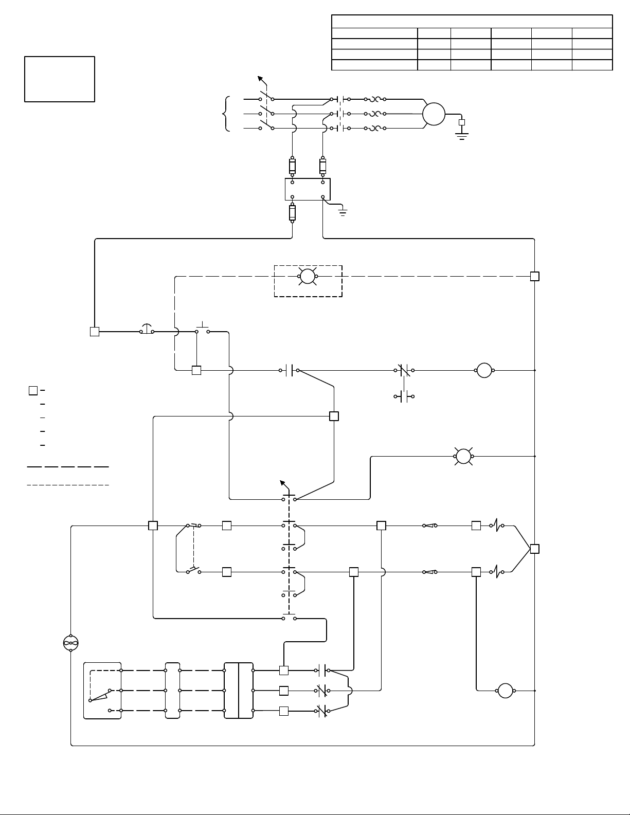
The electrical diagram for the machine is inside the cover of the control box. THE DIAGRAM IS ALSO
IN FIGURE 4. For electrical supply lines ten feet (3 m) or shorter, we recommend at least 12 and prefer-
ably 10, gauge wire. For longer supply lines, use at least 10 gauge and preferably, 8 gauge.
We do not recommend supply lines longer than twenty five feet (7.5 m).
POWER REQUIREMENTS:
Motor frame 3PH=182T 1PH=184T
MOTOR VOLTAGE FULL LOAD CURRENT
(VAC) (AMPS)
208 31
230 29.6
460 14.8
575 12
230 (single phase) 40
Motor power rating: 10hp Speed 1,725 RPM
KVA power rating: 7.9 KVA Frequency 60 HZ
Starting Current: 210% Full Load
PAGE 10
Page 11
3-PHASE
POWER
TERMINAL STRIP #
WIRE #
WIRE COLOR
COMPONENT TERMINAL #
NORMAL POSITION
OPTIONAL EQUIPMENT
COMPONENT
1
(2)
BLK
3
(XO)
FIGURE 4
LEGEND
SEE MOTOR TAG
FOR DETAILS
GND
T1
1FU
3FU
L3
L2
L1
1T
2FU
T3
T2 MTR
1DISC
1M 1OL
INCOMING SUPPLY
(BY CUSTOMER)
PROVIDE MAXIMUM
UPSTREAM
PROTECTION PER N.E.C.
CODE 430-52 AND TABLE
430-152.
FUSE REPLACEMENT
1FU & 2FU = FNQ-R-1
3FU = FNM-2
SEE TRANSFORMER FOR
WIRING DATA
OPTIONAL WORK LIGHT
AVAILABLE (1T MUST BE 250VA)
START
95 96
11413
97 98
2PB
A2
1M
A1
LX2
1OL
LED WORK LIGHT
E-STOP
1 2
1PB
2
1M 1413
G
1PL
GRN/YEL
X1 X2
3
RED
WHT
RED
4BLK
1FTS
1
(XOO) 2
3
(OOX) 4
5
(OOX) 6
2LS
7
9 10
9
1LS
2CVC
1CVC
X2
RED
RED
BLK
BLK
5
610
8
MANUALAUTO
(OXO)
START
1SS
BLUE
13
BROWN
GRN/YEL
12
11
1CR
21 22
32
31
4443
SOCKET
PROBE
MALE
FEMALE
BLOCK
TERMINAL
BLUE
BROWN
GRN/YEL
WHT
RED
BLK
SWITCH
PROBE
RUNNING
1FAN
A2
A1
1CR
(31)
(13)
(43)
(23)
(32)
(14)
(44)
(24)
BLK
GRAY
(LEFT)
(RIGHT)
11
(XOO) 12
(WHT)(BLK)
7
(XOO) 8
(32)
PN 017515 RATING TABLE
MAX. HP
MOTOR FLA
OVERLOAD
LINE VOLTAGE (3PH) 230
10
25
ZB32-32
460
10
12.5
208
10
27.6
ZB32-32
575
10
9.6
380
10
15.8
ZB32-16 ZB32-16 ZB32-16

Page 11A
PN 017523 RATING TABLE
MAX. HP
MOTOR FLA
OVERLOAD
LINE VOLTAGE (1PH) 230
10
40
ZB65-57
SINGLE
PHASE
POWER
TERMINAL STRIP #
WIRE #
WIRE COLOR
COMPONENT TERMINAL #
NORMAL POSITION
OPTIONAL EQUIPMENT
COMPONENT
1
(2)
BLK
3
(XO)
SEE MOTOR TAG
FOR DETAILS
GND
T1
1FU
3FU
L2
L1
1T
2FU
T3
T2 MTR
1DISC
1M 1OL
INCOMING SUPPLY
(BY CUSTOMER)
PROVIDE MAXIMUM
UPSTREAM
PROTECTION PER N.E.C.
CODE 430-52 AND TABLE
430-152.
FUSE REPLACEMENT
1FU & 2FU = FNQ-R-1
3FU = FNM-2
SEE TRANSFORMER FOR
WIRING DATA
OPTIONAL WORK LIGHT
AVAILABLE (1T MUST BE 250VA)
START
95 96
11413
97 98
2PB
A2
1M
A1
LX2
1OL
LED WORK LIGHT
E-STOP
1 2
1PB
2
1M 1413
G
1PL
GRN/YEL
X1 X2
3
RED
WHT
RED
4BLK
1FTS
1
(XOO) 2
3
(OOX) 4
5
(OOX) 6
2LS
7
9 10
9
1LS
2CVC
1CVC
X2
RED
RED
BLK
BLK
5
610
8
MANUALAUTO
(OXO)
START
1SS
RUNNING
1FAN
A2
A1
1CR
(31)
(13)
(43)
(23)
(32)
(14)
(44)
(24)
BLK
GRAY
(LEFT)
(RIGHT)
11
(XOO) 12
(WHT)(BLK)
7
(XOO) 8
(32)
BLUE
13
BROWN
GRN/YEL
12
11
1CR
21 22
32
31
4443
SOCKET
PROBE
MALE
FEMALE
BLOCK
TERMINAL
BLUE
BROWN
GRN/YEL
WHT
RED
BLK
SWITCH
PROBE
FIGURE 4A
LEGEND

WWW.SCOTCHMAN.COM
BEST
IN THE
BUSINESS
WARRANTY
S
C
O
T
C
H
M
A
N

4.5 MACHINE START-UP
BEFORE STARTING THIS MACHINE, TAKE TIME TO THOROUGHLY REVIEW THE VHS
SAFETY TAPE OR SAFETY CD AND THE OPERATOR’S MANUAL.
This machine is equipped with a lock-out, disconnect switch as standard equipment. We strongly urge
you to follow the OSHA directive CFR-1910.147 (effective 09-01-90) regarding lock-out, tag-out proce-
dures. BEFORE POWERING THE MACHINE, be sure that all packing materials and tools have been
removedfrom the machine and that all work stations are clear.
TO POWER THE MACHINE:
1. Place the disconnect switch (A) in the ON position and the selector switch (B) in the START position.
2. Power the machine by pushing the green START button.
Once the machine has been powered, it will not move until either RUN or AUTO is selected. If the ma-
chine does not move when the foot pedal is depressed, the motor rotation is not correct. The electrician
will have to switch two of the line wires to change the direction of rotation.
Any time that the power to the machine has been turned off, the selector switch must be placed in the
START position to restart the machine.
4.6 MACHINE STROKE INSPECTION & ADJUSTMENT
The stroke setting is important for the proper operation of the machine. If this setting has changed, the
machine may over-travel and cause the cylinder to "bottom out". This continued condition will eventu-
ally cause the starter overload to open. It can also cause the hydraulic oil to overheat and damage hy-
draulic system components.
A check of the machine’s stroke setting is made at the pivot end of the plate shear.
SEE FIGURE 5 ON THE FOLLOWING PAGE.
1. Set the stroke control handles (C) out to their farthest position.
2. Place the disconnect switch (A) in the ON position and the selector switch (B) in the START position.
3. Turn the run-auto switch (B) to the RUN position and allow the machine to return.
6. Turn the machine’s power off.
7. Check to see if the metering boss has contacted the left limit switch.
8. If it has not, loosen the four mounting plate screws (G) and move the mounting plate to the right until
contact is made.
9. Tighten the screws and re-check the dimensions. Repeat, if needed.
PAGE 12

PAGE 13
FIGURE 5

Page 14
The Scotchman Shear is an exceptionally rugged machine designed for long life with a minimum
amount of maintenance. A regular program of servicing will extend the life of the machine and prevent
costly down time.
5.0 MAINTENANCE
Re-oil the blades every 10 to 15 cuts.
The oil will allow the machine to shear easier and increase tool life considerably.
We recommend cutting oil or motor oil swabbed on with a brush or applied with a squirt can or a spray
applicator.
Grease the main pins daily.
(SEE FIGURE 6 ON THE FOLLOWING PAGE.)
Grease all other fittings twice per week.
Mobil Grease XHP 222 Special is recommended.
Once a month, check the oil level in the reservoir. It should be approximately 2 inches (50mm) below
the top of the reservoir.
The recommended hydraulic oil is a lightweight, non-foaming, hydraulic oil such as Mobil DTE 25 or
equivalent. The reservoir capacity is 24 U.S. gallons (91 liters).
5.1 LUBRICATION
IMPORTANT: Before operating the SHEARMASTER 610, apply oil to the bar shear blades.

Page 15
FIGURE 6
GREASE
POINTS
5.2 SCHEDULED MAINTENANCE
A program of scheduled maintenance should be set up and documented according to your application
and the frequency you use this machine.
The following is a list of some important items that should be included in a scheduled maintenance
program.
Since the 610 Shear can be used for a wide variety of applications, every user must design and implement
a scheduled maintenance program that fits their needs.
1. EVERY 500 HOURS OR SIX MONTHS:
B. Check the condition of all cutting blades on the machine.
C. Check the condition of the bushings in the shear beam. This can be done visually by watching the
beam for vertical movement while the machine is in operation. If vertical movement is noted,
block or support the beam with a lifting device and remove the main pin and check the clearance. If
the clearance exceeds twelve thousandths (.012) of an inch (.3mm), replace the bushing.
2. EVERY 1,500 HOURS OR 1 YEAR:
A. Change the hydraulic fluid in the reservoir and replace the filter. For recommended fluids, SEE SEC-
TION 5.1.

Page 16
When using the bar shear on your Scotchman Ironworker, always use the hold-down device. Never put
any part of your body between the hold-down and the material to be sheared. A maximum clearance of
1/8" (3mm) between the hold-down and the material to be sheared is acceptable.
The maximum tonnage available on the bar shear is to the left, or closest to the pivot point. For
applications that do not require the maximum tonnage, move the material to the right, for minimal
distortion of the drop off piece. Do not attempt to shear pieces that are too short for the hold-down to
grip as this will cause the material to "kick-up" and probably result in damage to the machine.
It is important that the hold-down is correctly adjusted (1/8" above the material) to avoid possible damage
to the machine and injury to the operator. The hold-down is adjustable to cover all thicknesses of material
within the rated capacity of the machine. A shear support table with adjustable guide is fitted to allow the
accurate feeding of material at any angle. The maximum material that can be sheared is 1 x 12 inch (25 x
305mm), 3/4 x 20" (19 x 508mm) mild steel.
The standard shear blades fitted to the machine comprise of two rectangular fixed blades. The shear
blades are symmetrical and each can be rotated to expose four (4) cutting edges. After a period of time
and subsequent dulling of the blades, the blades can be removed, rotated, and reinstalled back on the
machine. Blade Clearance must be checked whenever blades are changed. SEE FIG. 7A on page 18, and
FIG. 8 on page 19 for more information on setting the shear blade clearance.
Also, we have a curved Sabre Blade (P/N 422071) that can be can replace the standard upper shear blade.
The Sabre Blade makes it easier for the machine to shear and will increase it's shearing capacity slightly.
Keep in mind that the Sabre Blade has only two cutting edges (the curved side) and it will damage the
machine if installed upside-down!!
After rotating or grinding worn blades, they must be refitted and adjusted to clearances listed in this
section. But first, always make sure the shear arm is adjusted properly. The upper ’moving blade’ is not
adjustable and the lower ’fixed blade’ must be adjusted to suit. The securing and adjusting screws for the
lower 'fixed blade’ are more accessible when the shear table has been removed. An even clearance
between the ’moving’ and ’fixed blade’ along their entire length is important and attention should be
given to ensuring that the ’fixed blade’ is in a vertical plane. .
REFER TO SECTION 6.2A FOR SHEAR BLADE ADJUSTMENT.
REFER TO SECTION 6.2B FOR SHEAR ARM ADJUSTMENT.
6.1 BAR SHEAR OPERATION
CAUTION: WHEN THE BAR SHEAR STATION IS NOT IN USE, ALWAYS CRANK THE
HOLD-DOWN DEVICE TO ITS DOWN POSITION.
6.0 MACHINE OPERATION

Page 17
080430
080430
080061
080061
USE OUTER STOP PIN HOLES
FOR STORAGE OF GUIDE WHEN
NOT BEING USED
USE INNER STOP PIN HOLES
WITH GUIDE ORIENTATED AS
SHOWN FOR 90° CUTS ON
LEFT SIDE OF TABLE
REVERSE ORIENTATION FOR
USE ON RIGHT SIDE OF TABLE
ALIGN 45° NOTCH
FLUSH WITH EDGE OF
TABLE FOR MITERING
REVERSE ORIENTATION
FOR USE ON OTHER SIDE
FEED MATERIAL
FEED MATERIAL
FEED MATERIAL
FEED MATERIAL
ALIGN FRONT EDGE OF
90° NOTCHES FLUSH WITH
FRONT EDGE OF SLOTS IN
TABLE FOR 90° CUTS
AWAY FROM STOP PIN HOLES
STOP PIN
STOP PIN HOLE
GUIDE
BAR SHEAR GUIDE INSTRUCTIONS
SHEARMASTER 610
FEED MATERIAL
080061
080061
FIGURE 7
Other manuals for SHEARMASTER 610
1
This manual suits for next models
1
Table of contents
Other Scotchman Power Tools manuals


Popular Power Tools manuals by other brands

REED
REED SAWITSD 07615 operating instructions

Orgapack
Orgapack OR-T 200 Operating and safety instructions

Makita
Makita TM3000CX7 instruction manual

Metabo
Metabo BS 18 LT BL Q Original instructions

Campbell Hausfeld
Campbell Hausfeld DG460500CK Operating instructions and parts manual

Makita
Makita 4399D instruction manual

Bomag
Bomag BPR 70/70 D Operating and maintenance instructions

Klauke
Klauke EK 50/18CFB manual

EINHELL
EINHELL TC-CD 18/35 Li Original operating instructions

Rikon Power Tools
Rikon Power Tools 82-100 Operator's manual

Magna-Matic
Magna-Matic MAG-8000-7 operating instructions

DS Produkte
DS Produkte KT-03 instructions


