Scotchman PRESSPRO 110 User manual

You have downloaded a
manual for the
SCOTCHMAN
PRESSPRO 110
HYDRAULIC PRESS

www.scotchman.com
PRINTED DECEMBER 2022
PRESSPRO 110
HYDRAULIC
PRESS
SCOTCHMAN INDS. - 180 E US HWY 14 - PO BOX 850 - PHILIP, SD 57567 Phone: 1-800-843-8844 www.scotchman.com
S/N 2000 and higher
Page 2
PRESSPRO 110
SCOTCHMAN INDS. - 180 E US HWY 14 - PO BOX 850 - PHILIP, SD 57567 Phone: 1-800-843-8844 www.scotchman.com

TABLE OF CONTENTS
SCOTCHMAN INDS. - 180 E US HWY 14 - PO BOX 850 - PHILIP, SD 57567 Phone: 1-800-843-8844 www.scotchman.com
Page 3
SECTION DESCRIPTION PAGE #
1.0 INTRODUCTION
1.2
Warranty
Standard Features
2.0
3.0
4.0
3.2
3.3
3.4
INSTALLATION AND SET UP
Machine Moving Procedures
Pallet Jack
Forklift
Securing The PressPro 110
Mounting Brackets For Hydraulic Unit
Installation Of The Hydraulic Unit
Connecting Hydraulic Hoses
Electrical Requirements
Electrical Schematic
MACHINE CONTROLS
On/Off Switch
Emergency Stop Button
Pressure Control Valve
Oil Filler Plug
Speed Setting Valve
MACHINE START UP AND OPERATION
First Start Up
Positioning The Press Cylinder
Positioning The Table
OPERATING THE PRESSPRO 110
V-Block Set
PRESSPRO 110 MAINTENANCE
Changing The Hydraulic Oil
PRESSPRO HYDRAULIC SCHEMATIC
3.5
3.6
3.7
3.8
3.9
5.0
3.11
6.0
4.2
4.3
4.4
4.5
5.1
5.3
5.2
7.0
6.1
7.1
3.1
6.2 Working At Or Near Maximum Capacity
1.1
SAFETY PRECAUTIONS
3.10
4.1
8.0
PRESSPRO 110 PARTS LIST
9.0
9.1 Piston Parts
Cylinder Parts9.2
9.3 PressPro 110 Parts Diagram
Direction Control Valve
Hand Pump
4.6
4.7
4
5
14
13
11
22
21
19
18
17
16
15
26
25
23
22
33
32
31
30
29
27
4
5
7
7
23
23
25
30
34
34
35
36
24
24
10
10
Physical Dimensions & Technical Data
Hydraulic Reservoir

Page 4
1.0 INTRODUCTION
Our 110 ton hydraulic press is equipped with a movable cylinder (left-right) and an in-height adjustable
working table. Equipped with pressure regulation, 2 speeds, joystick and a hand pump for precision
pressing.
Smooth & precise, heavy-duty and versatile; This hydraulic press is industrial-grade and ideal for
assembly, straightening, fabrication, quality control, maintenance, product testing, bending, & forming.
The open side frame design allows for material to pass through and provides flexibility to work on the
longest work pieces. Built for the big jobs as well as the small ones; the adjustable H-frame bed height
offers increased versatility with its ability to raise and lower the table for the best working distance
possible
Meets CE Standards and comes with our 3-year warranty.
1.1 WARRANTY
Scotchman Industries Inc. will, within three years of date of purchase, replace F.O.B. the factory or
refund the purchase price for any goods which are defective in materials or workmanship, provided that
the buyer returns the warranty registration card within thirty days of the purchase date and, at the
seller’s option, returns the defective goods freight and delivery prepaid to the seller, which shall be the
buyer’s sole and exclusive remedy for defective goods.
Hydraulic and electrical components are subject to their respective manufacturer’s warranties.
This warranty does not apply to machines and/or components which have been altered, changed or
modified in any way or subjected to abusive and abnormal use, inadequate maintenance and lubrication
or subjected to use beyond the seller’s recommended capacities and specifications.
In no event shall seller be liable for labor cost expended on such goods or consequential damages.
The seller shall not be liable to purchaser or any other person for loss or damage directly or indirectly
arising from the use of the goods or from any other cause.
No officer, employee or agent of the seller is authorized to make any oral representations or warranty of
fitness or to waive any of the foregoing terms of sale and none shall be binding on the seller.
Any electrical changes made to the standard machine due to local electrical code variations must be paid
by purchaser.
As we constantly strive to improve our products, we reserve the right to make changes without
notification.
SCOTCHMAN INDS. - 180 E US HWY 14 - PO BOX 850 - PHILIP, SD 57567 Phone: 1-800-843-8844 www.scotchman.com

Page 5
2.0 SAFETY PRECAUTIONS
1.2 STANDARD FEATURES
• Heavy duty all-steel construction
• Industrial grade hydraulic system
• Ram moves laterally for added versatility
• 3 Ram speeds
• Joystick operation with hand pump option
• Removable ram cap to accept a variety of tooling
• Adjustable H-frame bed/table height offers increased versatility
• Open side-frame design allows for material to pass through
• Hydraulic-assist for table height adjustment to maximize operator safety
• Set of V-blocks to simplify your pressing jobs
• Pressure gauge to monitor force
• Meets CE standards
• Three year warranty
1. The operator of this machine must be qualified and well trained in the operation of the machine.
The operator must be aware of the capacities of the machine and its proper use. This manual is
not intended to teach untrained personnel how to operate machinery.
2. All of the guards, adjustable restrictors and awareness barriers must be installed on the machine
and kept in good working order. Promptly replace worn or damaged parts with authorized parts.
3. Never place any part of your body into or under any of the machine’s moving parts.
4. Wear the appropriate personal protective equipment. Safety glasses are required at all times,
whether operating, setting up or observing this machine in operation. Since heavy pieces of metal
with sharp edges can be processed on this machine, the operator should also wear steel-toed shoes
and leather gloves.
5. Strictly comply with all warning labels and decals on the machine. Never remove any of the labels
and replace worn or damaged labels promptly.

Page 6
6. Always disconnect and lock out the power when performing maintenance work or repairs. Follow
the procedures outlined in the operator’s manual.
7. Practice good housekeeping. Keep the area around the machine clear and well lit. Do not
obstruct the operator’s position by placing anything around the machine that would impede
the operator’s access to the machine.
8. Never modify this machine in any way without the written permission of the manufacturer.
9. Never leave this machine running unattended.
10. Do not use press when temperature is below 42℉ (+5C) or above 122℉ (+50C)
11. Set up a program of routine inspections and maintenance for this machine. Make all repairs
and adjustments in accordance with the manufacturer’s instructions.
• NEVER TURN OFF THE MACHINE WHEN PRESSING FORCE IS BEING APPLIED
TO THE WORK PIECE.
• UNEXPECTED FORCE EXPANSION WHEN RESTARTING CAN DAMAGE THE
MACHINE OR INJURE THE OPERATOR.
• THEREFORE ALWAYS RELEASE THE FORCE FROM THE OBJECT, MOVE THE
PISTON UPWARDS AND THEN SAFELY TURN OFF THE PRESS.
WARNING: ALWAYS RELEASE JOYSTICK BEFORE TURNING OFF THE PRESS AND
JOYSTICK MUST BE IN MIDDLE POSITION WHEN STARTING THE PRESS.
► NOTE: ANY WELDING OPERATIONS ON THE PRESS TABLE ARE PROHIBITED.
THIS CAN DAMAGE THE MACHINE!!
► NOTE: THE MACHINE MUST BE BOLTED TO THE FLOOR - SEE SECTION 3.5
• NEVER USE A MACHINE UNLESS IT'S BOLTED TO THE FLOOR.
• IT CAN TIP OVER IF HEAVY PARTS ARE LOADED ON THE TABLE.
• THIS CAN CAUSE SEVERE INJURY OR DEATH!!
• USE THE PRESS IN THE VERTICAL POSITION ONLY.
► NOTE: MAXIMUM PRESSING FORCE CAN BE EXERTED FOR A SHORT TIME ONLY.
DO NOT USE MAXIMUM FORCE WHEN THE PISTON IS EXTENDED FURTHER
THAN 3/4 OF ITS LENGTH. THIS CAN DAMAGE THE PISTON - SEE SECTION 6.2

Page 7
3.0 INSTALLATION AND SET UP
CAUTION: THIS SECTION DISCUSSES INSTALLATION AND SET-UP PROCEDURES.
PLEASE READ THOROUGHLY BEFORE OPERATING THIS MACHINE.
3.1 PHYSICAL DIMENSIONS & TECHNICAL DATA
The following pages show the PressPro 110 physical dimensions, capacities, moving procedures, how to
secure the press in it's final location, mounting the hydraulic unit and hoses, how to fill the hydraulic
system, the electrical requirements and connections, and initial start up procedure. Following these
instructions ensure the press is set up properly and will help to ensure the safe operation and long life of
your new Scotchman PressPro 110 press.
UPON DELIVERY, DO NOT SIGN FOR ANY MACHINE UNTIL YOU HAVE REMOVED THE
PLASTIC AND INSPECTED EVERYTHING FOR DAMAGE!
• It is the customer’s responsibility to inspect the arriving machine.
• Make sure to note any damages on the delivery ticket and then immediately contact Scotchman
Inds. about the damage so we can assist you. Our toll free number is 1-800-843-884.
• If the driver will not wait for you to inspect the shipment, simply mark the shipment as
“damaged” before signing.
• It is unlikely that we can recoup any costs from damages not noted on the delivery ticket.
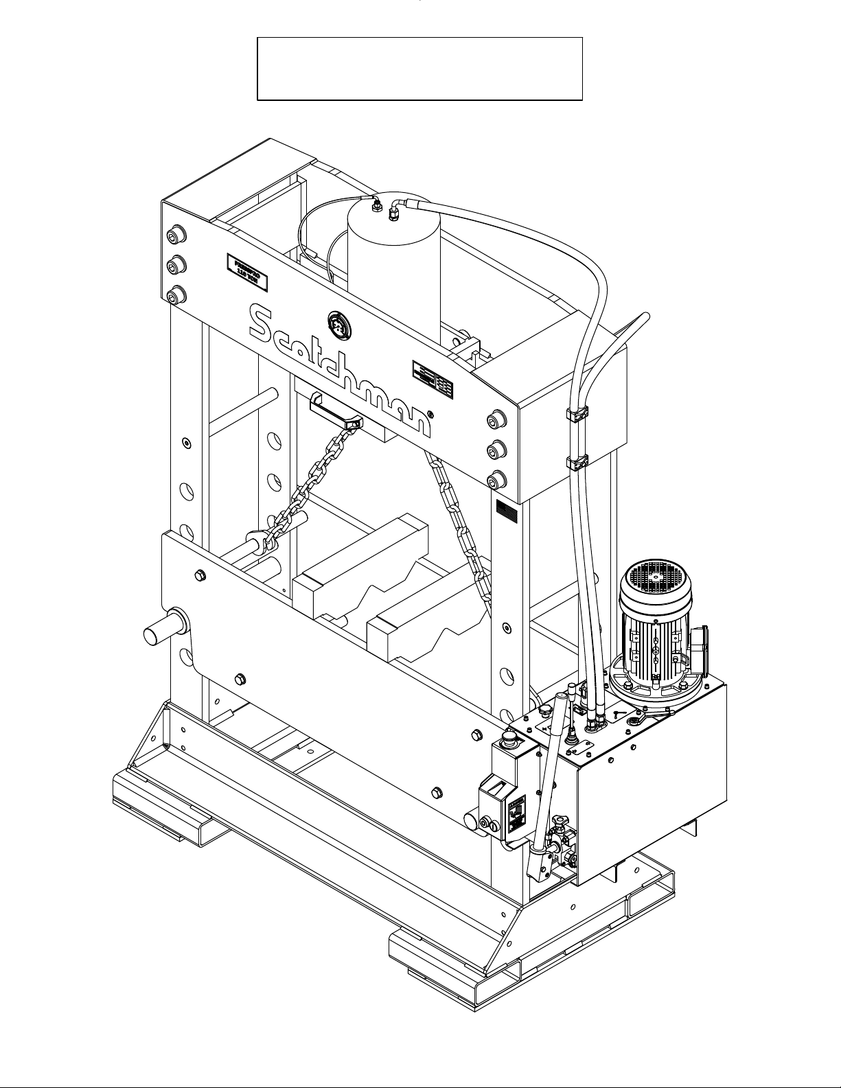
The press is delivered in the following condition:
• Table is in lowest position.
• Hydraulic unit mounted on the inside of the frame.
• Lifting chain packed in a separate box.
• Cylinder fixed in the middle of the press.
• Hydraulic unit without oil.

FIGURE 1
Page 8
M
L
PLACE V-BLOCKS
OR TABLE HERE
PRESSPRO
110 TON
H
I
A
E
C
J
D
B
F
CROSS BEAM ASSY.
TOP POSITION
CROSS BEAM ASSY.
BOTTOM POSITION
G
O
N
K
A
B
C
D
E
F
G
H
J
K
MM
I
UNITS INCHES
L
M
MM
UNITS INCHES
N
O
84-3/4 2153
54-1/4 1378
30 762
43-1/4 1099
12-1/8 308
66-1/2 1689
1375-3/8
8-11/16 221
21-1/2 546
32-3/4 832
4-3/4 121
16-5/16 414
36414-5/16
34313-1/2
121948
PRESSPRO 110 SPECIFICATIONS

Page 9
CAUTION: MAXIMUM PRESSING FORCE CAN BE EXERTED FOR A SHORT TIME ONLY.
DO NOT USE MAXIMUM FORCE WHEN THE PISTON IS EXTENDED FURTHER
THAN 3/4 OF ITS LENGTH. THIS CAN DAMAGE THE PISTON.
► NOTE: THE GIVEN PARAMETERS OF THE PISTON MOVEMENTS ARE MAXIMUM
VALUES AND CAN BE UP TO 25% LOWER.
PARAMETERS ARE VALID WITH MINIMUM OIL TEMPERATURE OF 86°F (30°C).
Press Force
Maximum Pressure
Cylinder Stroke
Oil Flow (Approaching)
Total Oil Capacity
(Tank and Cylinder Capacity)
Oil Type (See Pg. 13)
Press Speed
Return Speed
Weight
Diameter Cylinder
Diameter Piston Rod
Diameter Piston Head
US tons
psi
in.
gal/min
gallons
in/sec
pounds
in.
in.
in.
in/sec
in/sec
gal/min
Approach Speed
Oil Flow (Press)
kN
-
110 981
3750 260
15 380
415.4
1.4 5.3
12.2 46
HL46
.265 6.74
.091 2.32
8.66 220
3.54 90
4.72 120
3000 1361
bar
mm
ltr/min
liters
mm/sec
Kg
ltr/min
-HL46
mm/sec
mm
mm/sec
.319 8.09
mm
mm
PRESSPRO 110 CAPACITIES
Motor
Voltage
Frequency
Revolutions Per Minute (60Hz)
Insulation Protection
Insulation Classification
hp
V
Hz
IP
230 3ph or 460 3ph All Models
60
1680
55
F
rpm
kW
Full Load Amps FLA 230V - 10A 460V - 5A
IC
2.6
PRESSPRO 110 VOLTAGE SPECIFICATIONS
3.5

Page 10
3.2 MACHINE MOVING PROCEDURES
WHEN USING A PALLET JACK, ADHERE TO THE FOLLOWING PRECAUTIONS:
• Place the table in its lowest position.
• Remove the hydraulic unit. (See Sect. 3.7 and 3.8)
• Fix the cylinder in the middle of the press.
• DO NOT USE A NARROW PALLET JACK
• For stability, Pallet Jack must be wide enough to just fit between rectangle tubes.
• See FIGURE 2 on the next page.
The PRESSPRO 110 weighs 3000 lbs. Make sure the pallet jack you use has enough capacity to safely
lift the weight the press and follow the instructions below.
3.3 PALLET JACK
CAUTION: Use extreme caution when moving press as it is TOP HEAVY. When moving the press
with a pallet jack, it must be on a smooth level surface! Have more than one person
help you. Watch the press at all times. Go slowly with smooth movements. Unexpected
movements can make the press tip over and possibly cause serious injury or death.
The most common method of moving the PressPro 110 is with a pallet jack or a fork lift. The following
section shows the correct way to safely move the press without damage or injury.
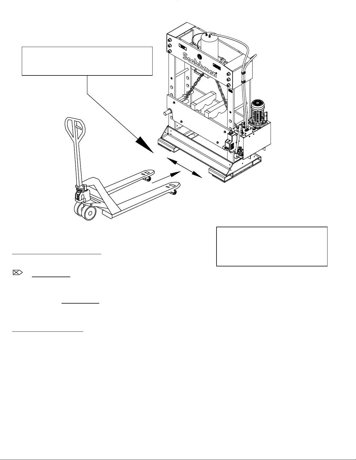
FIGURE 2
Use a Pallet Jack that just fits
between rectangular tubes
PRESS IS TOP HEAVY!
Use Extreme Caution
when moving!
3.4 FORKLIFT
CAUTION: PRESS IS VERY TOP-HEAVY!
Refer to FIGURE 3 on the next page for the below.
Page 11
UPPER SUPPORTS:
• Place the table in its lowest position.
• Keep forks as wide as possible.
• Do not lift the press any higher than needed.
• Go slowly with smooth movements and only on level surface.
• Have another person watch for problems.
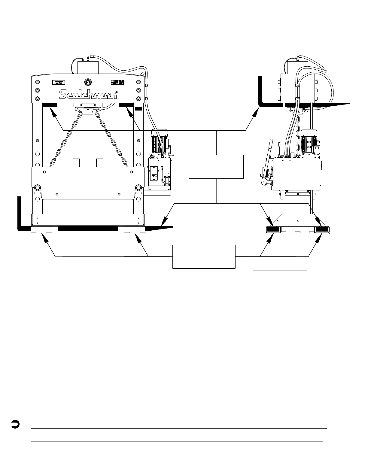
FIGURE 3
Upper Supports: Keep forks as
wide as possible as shown below.
Rectangle Tubes:
The safest and
recommended way to
move press
RECTANGLE
TUBES
FORKLIFT
FORKS
Page 12
PLACING THE FORKS THRU THE RECTANGLE TUBES PREVENTS PRESS FROM
TIPPING OVER. THIS IS THE SAFEST AND RECOMMENDED WAY TO MOVE IT.
RECTANGLE TUBES:
• Make sure the forklift forks are long enough to reach through all four rectangle tubes.
• Do not lift the press any higher than needed.
• Go slowly with smooth movements.
• Going straight up or down a slight incline is allowed ONLY if using rectangle tubes.
• Have another person watch for problems.

When the machine is positioned in the desired location, it should be bolted to a flat, smooth, level
concrete floor using 10 mm (3/8") screws and plugs (not included). The PressPro 110 has six holes
available in the base for this, three on each side. FIGURE 4 below is a view of the underside of the
machine showing the location of these holes. They are on the inside of the base of the press.
3.5 SECURING THE PRESSPRO 110
Mounting Holes for securing press to concrete floor
Page 13
UNDERSIDE VIEW OF PRESSPRO 110
FIGURE 4
37 in.
6 in.
12 in.
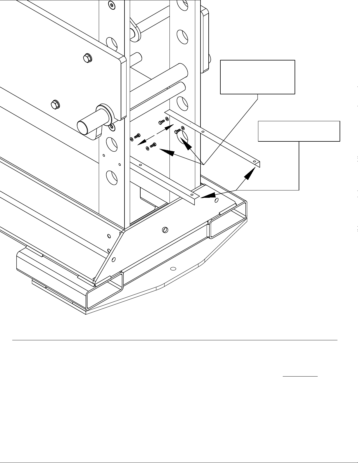
There are two brackets included that are used to mount the power unit on. They need to be installed so
the longer part is pointing to the outside of the machine as shown on the next page in FIGURE 5. Each
bracket should be bolted to a leg with two bolts and two washers.
3.6 MOUNTING BRACKETS FOR HYDRAULIC UNIT
FIGURE 5
BOLTS &
WASHERS
BRACKETS
Page 14

The Hydraulic Power Unit mounts on top of the brackets (shown in the previous section) with four bolts,
four nuts, and eight washers as shown below.
3.7 INSTALLATION OF THE HYDRAULIC UNIT
► NOTE: THE HYDRAULIC UNIT WEIGHS 130 LBS.
WHEN PLACING THE UNIT IN THE
CORRECT POSITION, MAKE SURE TO
USE ENOUGH MAN OR MACHINE
POWER TO LIFT THE UNIT.
HYDRAULIC UNIT
BOLTS TO
BRACKETS AS
SHOWN
ISOMETRIC VIEW OF
HYDRAULIC UNIT AND
MOUNTING BRACKETS
FIGURE 6
Page 15

FIGURE 7
Page 16
Once the hydraulic unit is mounted, the hoses must be attached.
On top of the cylinder there are (2) threaded holes. The centered hole is for the large diameter (18mm)
hose from the reservoir. The other hole is for the small diameter (5mm) pressure gauge hose.
Make sure there are no sharp bends in the hoses between the clamps and connections to the hydraulic
unit as shown below.
3.8 CONNECTING HYDRAULIC HOSES
MAKE SURE ALL HOSES ARE TIGHTENED SECURELY AND CONNECTED IN THE
CORRECT LOCATION BEFORE FILLING RESERVOIR AND OPERATING THE PRESS
FRONT
BACK
A
C
HANDLE AND
SCREW REMOVED
HANDLE INSTALLED IN
CORRECT ORIENTATION
PLACE HOSE MOUNTS ON
SAME SIDE AS POWER UNIT
(SHOWN ON RIGHT SIDE HERE)
IF 2 SPEED HANDLE IS IN AN UNDESIRABLE
POSITION REMOVE HEX HEAD SCREW AND
HANDLE, THEN REASSEMBLE IN CORRECT
ORIENTATION. (MAKE SURE HANDLE CAN
MOVE FROM HIGH SPEED TO LOW SPEED)
PRESSURE GAUGE GOES
IN THE HOLE THAT IS
NOT IN THE CENTER
90° FITTING GOES IN HOLE
CENTERED IN CYLINDER
TOP HOSE GOES TO
FRONT FITTING ON
THE POWER UNIT
BOTTOM HOSE GOES TO
THE BACK FITTING ON
THE POWER UNIT

CAUTION: NEVER RUN THE PRESS WHEN ITS LOW ON OIL. THIS WILL DAMAGE THE
HYDRAULIC UNIT AND CAUSE THE PRESS TO MALFUNCTION.
Oil Tank
Capacity
Gal. / Liter
PressPro 110 8.5 / 32.2
Cylinder
Capacity
Gal. / Liter
Total Oil
Capacity
Gal. / Liter
3.7 / 14 12.2 / 46
Press
Model
Page 17
The press is delivered without oil. Before initial start up, the tank needs to be filled.
Mobile DTE 10 Excel 46 or Mobile DTE 25 or similar hydraulic oil is recommended.
To properly fill the oil tank remove the filler plug on top of the hydraulic unit.
Fill the tank with a sufficient amount of oil. See bottom of page for the capacities of this press.
• The oil level is viewed in the sight glass located in the rear of the hydraulic unit.
• Replace the filler plug.
• Follow the instructions in SECT. 5.1 FIRST START UP to deaerate the hydraulics and
prepare the press for use.
3.9 HYDRAULIC RESERVOIR

• The machine must be connected to 220V 3ph or 440V 3ph power.
• To ensure satisfactory machine performance, the supply voltage should (+ or -) 10% of the motor
voltage rating. Check the machine data tag for full load current requirements.
• For electrical supply lines ten feet (3m) or shorter, we recommend at least 12 gauge, and
preferably, 10. For longer electrical supply lines, use at least 10 gauge, and preferably, 8.
• We do not recommend supply lines longer than twenty five feet (7.5m).
• The electric circuit must be protected by a fuse or circuit breaker with an adequate rating.
• The motor direction can be changed by swapping (2) of the incoming phases - See SECT. 3.11.
• The motor must be running in correct direction before the system can be de-aerated (SECT. 5.1)
3.10 ELECTRICAL REQUIREMENTS
CAUTION: TO PREVENT DAMAGE TO THE MOTOR AND DANGER TO THE
OPERATOR, ALL ELECTRICAL CONNECTIONS SHOULD BE MADE
BY A LICENSED ELECTRICIAN.
Page 18
► NOTE: CHECK WHICH DIRECTION THE MOTOR IS TURNING. LOOKING AT THE
MOTOR FROM ABOVE, MAKE SURE THE MOTOR IS TURNING THE
DIRECTION INDICATED BY THE ARROW.
CAUTION: IF THE MOTOR IS RUNNING IN THE WRONG DIRECTION, IT CAN
DAMAGE THE MACHINE IN A VERY SHORT TIME!!

3.11 ELECTRICAL SCHEMATIC
FIGURE 8
SCHEMATIC
L3
L2
L1 T1
T3
MTR
1M 1OL
T2
INCOMING SUPPLY
(BY CUSTOMER)
PROVIDE MAXIMUM
UPSTREAM
PROTECTION PER N.E.C.
CODE 430-52 AND TABLE
430-152.
GND
95 96
1OL E-STOP
1 2
1PB
START
3
4
2PB
A2
1M
A1
1M
1314
L1
L3
L2
SEE MOTOR TAG
FOR DETAILS
Page 19
Table of contents
Other Scotchman Power Tools manuals


