7
IMPROPER USE MAY CASUE
BREAKAGE AND SERIOUS INJURY
DO
DO always handle and store
wheels in a careful manner.
DO visually inspect all wheels
before mounting for possible
damage and ring test vitried
wheels
DO check machine speed against
the established maximum safe
operating speed marked on the
wheel.
DO check mounting anges for
equal and correct diameter.
DO use mounting blotters when
supplied with the wheels.
DO be sure work rest is properly
adjusted (center of wheel or
above; no more thatn 1/8” away
from wheel).
DO always use a safety guard
covering at least one-half of the
grinding wheel.
DO allow newly mounted wheels
to run at operating speed, with
guard in place, for at least one
minute before grinding.
DO always wear protective safety
glasses and additional eye & face
protection if required.
DO NOT
DO NOT use a cracked wheel or one
that has been dropped or become
damaged.
DO NOT force a wheel onto the
machine or alter the size of the
mounting hole - if wheel will not t the
machine, get one that will.
DO NOT ever exceed maximum
operating speed established for the
wheel.
DO NOT use mounting anges on
which the bearing surfaces are not
clean, at and free of burrs.
DO NOT tighten the mounting nut
excessivly.
DO NOT grind on the side of the
wheel (see ANSI Code B7.1 for
exception).
DO NOT start the machine untile the
wheel guard is in place.
DO NOT jam work into the wheel.
DO NOT stand directly in front of a
grinding wheel whenever a grinder is
started.
DO NOT force grinding so that the
motor slows noticeably or work gets
hot.
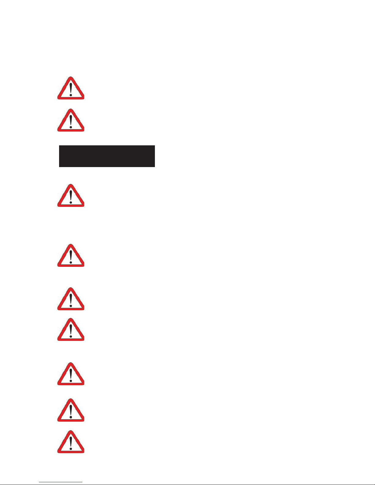
WARNING
IMPORTANCE OF PROPER MACHINE MAINTENANCE
Grinding is a safe operation if the few basic rules listed below
are followed. These rules are based on material contained
in the ANSI B7.1 Code for “Use, Care, and Protection of
Abrasive Wheels.” For your safety, we suggest you benet
from the experience of others and carefully follow these
rules.