Scott Aerator Aquasweep User manual

We at Scott Aerator thank you for your purchase. It is our goal to ensure
you are completely satised with your new AquaSweep and it continues
to operate smoothly for many years to come. Please take a few moments
to read through this document for proper assembly, installation and
maintenance to maximize the operating life of the unit.
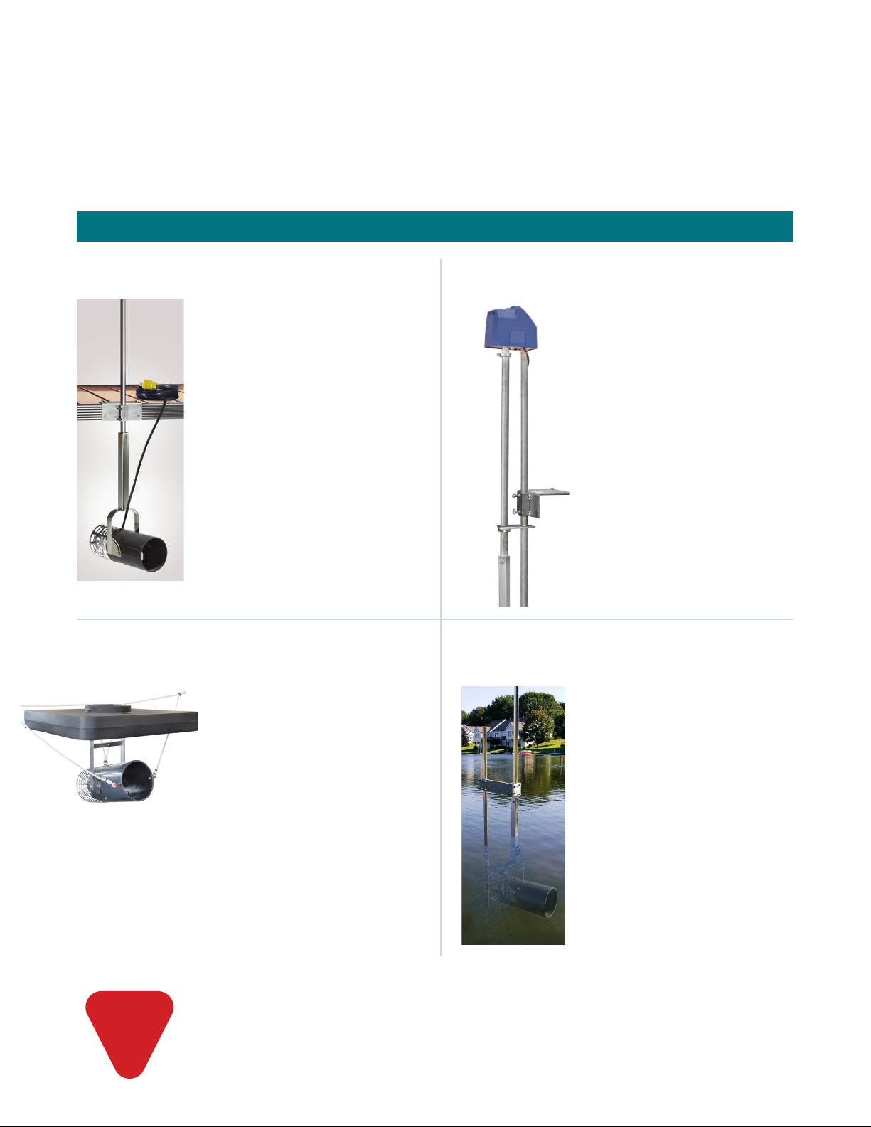
Aquasweep Dock Mounting (Page 3)
Aquasweep with Freestanding Pole (Page 6)
This Kit Includes
1 - Aquasweep 8" Housing/Yoke
1 - Stainless Steel Debris Shield
1 - Stainless-Steel Pole
1 - Dock Mounting Plate
1 - Packet of Lubricating Compound
2 - Thumb Screws
3 - Small Self Tapping Screws
4 - Large Phillips Head Screws
Tools Needed
One 3/8" Wrench or Socket Screwdriver
One Phillips Style Screw Driver
Two 1/2" Wrenches (Or Pliers)
Drill and 1/4" drill bit
Aquasweep with Oscillator (Dock Mount Only - Page 4)
This Kit Includes
1 - Aquasweep 8" Housing/Yoke
1 - Stainless Steel Debris Shield
1 - Oscillator Assembly
1 - Dock Mounting Plate
1 - Packet of Lubricating Compound
2 - Thumb Screws
3 - Small Self Tapping Screws
4 - Large Phillips Head Screws
1 - 3/16" Hex Wrench
Tools Needed
One 3/8" Wrench or Socket Screwdriver
One Phillips Style Screw Driver
Two 1/2" Wrenches (Or Pliers)
Drill and 1/4" drill bit
Aquasweep Floating (Page 5)
This Kit Includes
1 - Aquasweep 8" Housing/Bracket
1 - Stainless Steel Debris Shield
1 - Float Platform
2 - 3" Eyebolts/Washers/Locks Nuts
3 - Small Self Tapping Screws
2 - 3/8" x 50' braided nylon rope
Tools Needed
One 3/8” Wrench or Socket Screwdriver
Two 1/2” Wrenches (Or Pliers)
This Kit Includes
1 - Aquasweep 8" Housing/Yoke
1 - Stainless Steel Debris Shield
1 - Stainless Steel Pole
1 - 4 Prong Stabilizer
1 - Dock Post Mounting Bracket
1 - Stainless Steel Mounting Pole
1 - 24" Driving Sleeve
3 - Small Self Tapping Screws
Tools Needed
One 3/8" Wrench Or Socket Screwdriver
Two 1/2" Wrenches (Or Pliers)
!Only connect to a GFCI Protected Circuit
Always disconnect the power when swimmers are present
Do NOT use an extension cord to supply power to the motor
In This Guide
1

1/3 HP
115V
1/2 HP
115V
1/2 HP
230V
3/4 HP
115V
3/4 HP
230V
1 HP
115V
1 HP
230V
SPECIFICATIONS
WAT Ts 630 670 670 875 940 1094 1210
AMPs 8 10 510.7 6.8 11.5 8.2
RPM 3450 3450 3450 3450 3450 3450 3450
GALLONS/MIN 300 400 400 450 450 500 500
FLOW DISTANCE 40' 50' 50' 60' 60' 75' 75'
OSCILLATOR DIA 80' 100' 100' 120' 120' 150' 150'
MAXIMUM CABLE RUN IN FEET FROM BREAKER
CABLE SIZE
12 GA 175' 160' 650' 125' 480' 100' 400'
10 GA 275' 250' 1020' 200' 760' 150' 630'
8 GA 430' 390' 1610' 300' 1200' 225' 990'
6 GA 680' 620' 2510' 500' 1870' 400' 1540'
4 GA 1050' 960’3880' 860' 2890' 770' 2380'
2 GA 1600' 1460’5880' 1300' 4370' 1160' 3610'
CABLE
SUPPLIED
50'
12 GA
50'
12 GA
50’
12 GA
50’
10 GA
50’
12 GA
50’
10 GA
50’
12 GA
DO NOT USE AN EXTENSION CORD TO SUPPLY POWER TO THE MOTOR
Propeller
Part # 30005
Maintenance, Winterizing, Storing
Our products require very little to no maintenance. Under normal operating conditions, you should enjoy many years of
trouble-free service from the unit. As a rule of thumb, the propeller assembly on our AquaSweep should be changed every
three years. This is a simple procedure that can be done on-site. When the unit is removed from the water for the propeller
switch, it would be a good opportunity to wash the unit down with high pressure water. Once the unit is clean, a visual
inspection of the entire AquaSweep is recommended to be certain nothing is restricting water ow.
The AquaSweep has been engineered to be operated all year or unplugged and left installed throughout the winter.
If the AquaSweep is ever removed from the lake or pond, it is essential to store with pump submerged in a 5 gallon
bucket of water to avoid damage to the pump seals.
Oscillator Kit
Dock Mount Only
Part #165750
Dock Mounting Plate
Part #20026
Dock Post
Mounting Bracket
Part #16501
AquaSweep Specications
Parts and Accessories
2
For additional replacement parts, contact us at 800-928-3745
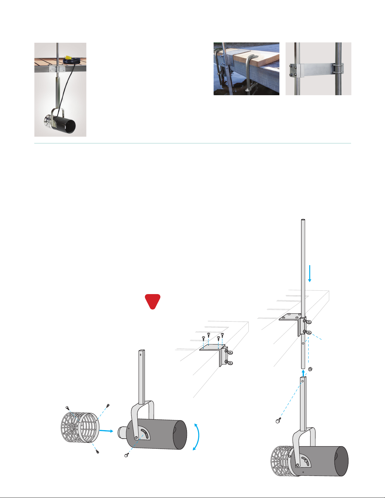
Fig. 4
Yoke Assembly
12"
Dock
Mounting
Stainless
Steel
Pole
Plate
Fig. 3
Thumb
Screws
Fig. 5
3/8"x 2"SS Bolt/Nut
Aquasweep
Housing
Angle Adjustment
SS Debris Shield
Fig. 2
Fig. 1
3
Dock Mount Assembly and Installation
For repositionable installation
along longer docks, consider
fastening dock mounting
bracket to a 2" x 10" x 24"
board and securing to dock
with sturdy C-clamps.
(optional) Dock Post
Mounting Bracket
Fits posts up to 2-1/2" Dia.
Part #16501
Accommodates Larger
U-clamp rings up to 4" Dia.
Determine location that will best
position the Aquasweep to clear
debris, in a minimum water depth
of 12". Adjust depth 4" from lake
bottom. See back page for additional
guidelines.
Check that the dock framing is sturdy
and will accept mounting bracket
screws. Housing angle and direction
can be adjusted as needed to clear
muck and debris a full 360° area.
1. Begin the assembly of your
AquaSweep dock mount model by
removing the stainless-steel bolt
from the yoke assembly. Adjust
the AquaSweep housing 90° to the
yoke and tighten bolt. Fig. 1
2. Next, align the 3 holes on the
stainless steel debris shield with the
3 pre-drilled holes on the housing
and fasten with the 3 small self-
tapping screws provided. Fig. 2
3. Secure the dock mounting bracket
to your wooden or metal dock,
utilizing the 4 phillips head screws.
If necessary, drill pilot holes to
prevent cracking of deck material.
Fig. 3
4. Once the dock mounting bracket
has been secured, the stainless-
steel pole can be inserted thru the
dock mounting bracket. Simply
loosen the 2 thumb screws from
the dock plate sleeve, insert the
pole from the top thru the sleeve by
approximately 12 inches, and then
retighten the 2 thumb screws. Fig. 4
Oscillator Fig. 6
Adjust for varying water levels by
loosening the 2 thumb screws from
the dock mounting bracket and
raising or lowering the AquaSweep.
Please note, the 2 thumb screws
are coated with a special lubricating
compound specically designed
for stainless-steel to ensure proper
function. An extra packet of this
compound has been included
with your AquaSweep purchase;
periodic lubrication of the 2 thumb
screws is required for years of
problem free use and for warranty
validation.
For oscillator installation, continue
on page 4
5. Now, slide the yoke assembly
over the bottom of the stainless-
steel pole and secure with the bolt
provided. Fig. 5
6. Finally, power can be supplied
to your AquaSweep utilizing a
standard 110 or 230 volt receptacle
protected by a GFCI.
Extension cords must not be
used. Always disconnect power
when swimmers are present.
!
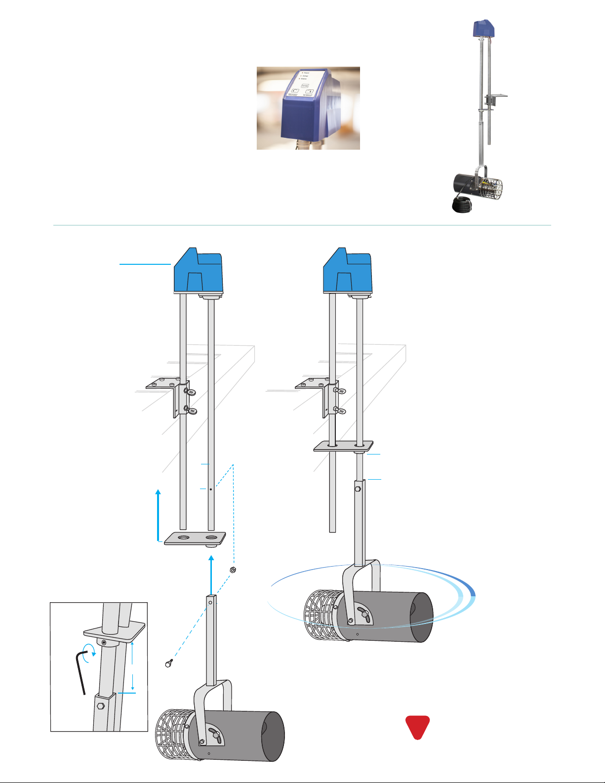
Oscillator
(front display side)
Fig. 6
Fig. 7
Fig. 8
Stabilizer Flange
5"
5"
5"
3/8" x 2" SS Bolt /Nut
0°- 359°
Sweep
Yoke Assembly
5. Slide the Stablizer Flange up
onto both Oscillator poles,
with the larger copper bushing
facing downward on the front
rotating pole. Do not tighten at
this time. Fig. 6
6. Slide the yoke assembly over
the bottom of the rotating pole
with stainless steel debris shield
facing towards front display.
Secure with the bolt and nut
provided. Fig. 7
7. Secure the Stablizer Flange 5”
from the upper edge of the yoke
with the supplied hex wrench.
Fig. 8
4
Oscillator Assembly and Installation (Dock Mount Aquasweep Only)
Weathproof control unit
allows for start and stop
positioning from 0-359°.
Our fully programmable oscillator
attachment makes moving muck even
easier. No need to turn the AquaSweep in
its mounting; the oscillator does it for you!
We pre-program the oscillator to rotate
the AquaSweep in 20 degree increments
every 20 minutes; you set it for any radius
you wish. The oscillator attachment can be
added to any new or previously installed
dock-mounted Aquasweep.
For assembly with a new
Aquasweep, follow steps 1-4 for
yoke assembly and dock mounting
bracket installation on page 3.
If addding to an installed
Aquasweep, begin by removing
bolt that secures the stainless
steel pole to the yoke assembly.
The oscillator replaces the
stainless steel pole on your dock
mount Aquasweep.
See back for setting the
Aquasweep controls
Extension cords must not be
used. Always disconnect power
when swimmers are present.
!

5
Freestanding Aquasweep Assembly and Installation
Determine location that will best
position the Aquasweep to clear
debris, in a minimum water depth
of 12". Adjust depth 4" from lake
bottom. See back page for additional
guidelines.
Ground should be solid enough to
ensure stable pole mounting. Housing
angle and direction can be adjusted as
needed to clear muck and debris a full
360° area.
6. Push the pronged mounting pole into
the bottom of the lake/pond in the
desired position. The location should
be no less than 12" deep. Slide the
included 24" drive sleeve over the top
of the freestanding pole and pound
the mounting pole into the lake/pond
bottom until secure. Fig. 6
7. Now, secure the Aquasweep
assembly to the freestanding pole with
2 U-bolts, washers and nuts. Fig. 7
8. Adjusts for varying water levels
by loosening the 2 U-bolts
and raising or lowering the
AquaSweep.
9. Finally, power can be supplied
to your AquaSweep utilizing a
standard 110/230 volt receptacle
protected by a GFCI.
It is best to have two
people during installation.
Fig. 4
3/8"x 2"
SS Bolt/Nut Fig. 5
3/8"x 2"
SS Bolt/Nut
Fig. 7
U-Bolts
Fig. 6
Fig. 3
Yoke Assembly
Fig. 1
Angle
Adjustment
Fig. 2
SS Debris Shield
Aquasweep
Housing
Stabilizing
Prongs
Mounting
Pole
24" Drive
Sleeve
Mounting
Bracket x4
1. Begin by removing the stainless-steel
bolt from the yoke assembly. Adjust
the gray Adjust the AquaSweep
housing 90° to the yoke and tighten
bolt. Fig. 1
2. Next, align the 3 holes on the
stainless steel debris shield with the
3 pre-drilled holes on the housing
and fasten with the 3 small self-
tapping screws provided. Fig. 2
3. Secure the mounting bracket to the
stainless steel pole. Loosen screws,
slide over pole near top edge of the
yoke, align in same direction as hole
that secures yoke assembly and
retighten bolts. Fig. 3
4. Insert the stainless steel pole into
yoke assembly, aligning the holes,
and secure with included 2" bolt and
locking nut. Fig. 4
5. Hold freestanding pole pointed end
down and slide stabilizing prongs
from top until holes are aligned.
Secure with the included 2" bolt and
nut. Fig. 5
Extension cords must not be
used. Always disconnect power
when swimmers are present.
!
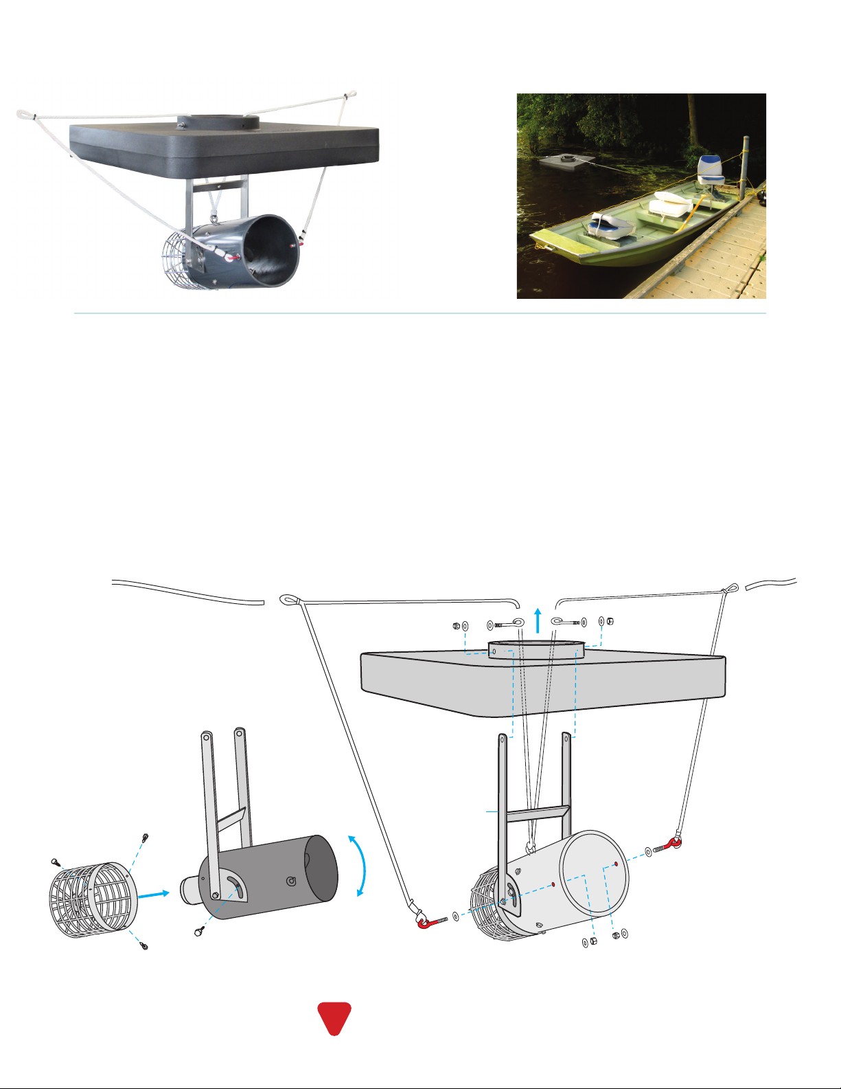
Fig. 1
Fig. 3
Fig. 4
Fig. 5
Yoke Assembly
Fig. 2
Angle Adjustment
Float
Bracket
Float
Rope Securement
SS Debris Shield
Aquasweep
Housing
1. Remove hex cap bolt, washer and
locking nut from the oat bracket.
Tilt the oat bracket to align holes
to the desired angle of water ow,
typically 45°, and resecure. Fig. 1
2. Next, align the 3 stainless steel
debris shield holes with the 3 pre-
drilled holes on the housing and
fasten with the 3 small self-tapping
screws provided. Fig. 2
3. Place oat above the oat bracket.
Align the holes in the oat with the
top hole in the oat bracket. Draw
the rope up through the oat. Insert
the long eyebolts and washer from
inside, through oat bracket and
oat and secure with washers and
locknuts. Fig. 3
4. Feed the red eye-bolts through the
red marked holes in the housing and
secure with washers and locknuts.
Fig. 4
5. Tie 2 lengths of rope included with
the unit to the loops in the white
rope. Secure rope ends as low as
possible to docks or pilings and
adjust tension to achieve position
that works best. If the oat has a
tendency to rise when the unit is on,
move loops down 3-4 inches. Fig. 5
6. Finally, power can be supplied
to your AquaSweep utilizing a
standard 110/230 volt receptacle
protected by a GFCI.
6
Extension cords must not be
used. Always disconnect power
when swimmers are present.
!
A great solution for
extending Aquasweep
performance beyond
the dock or in greater
depths.
Floating Aquasweep Assembly and Installation

13245 Barry Street, Holland, MI 49424
scottaerator.com information@scottaerator.com
800-WATER-45 (800-928-3745) (616) 392-8882
The Scott Aerator Awesome Warranty
All standard Scott Aerator products are unconditionally warranted for ve years against motor defects in materials or workmanship,
under normal operating conditions. All other product components are warranted for one year from date of purchase. Scott Aerator
will repair or replace failed parts under warranty when the defective unit is returned to the factory, shipping prepaid, and factory
inspection establishes that the part was defective. The unit must be returned to the factory prior to shipment of replacement parts. All
parts replaced under this warranty will be returned with shipping prepaid. Scott Aerator will not be liable for consequential damage
nor for any costs associated with removal or attempts to repair components in the eld.
Made in America
Oscillator Programming Instructions
1. Plug in - green power light will be ON
2. Press Setup button - red power light will come ON
3. Press and hold button with arrow pointing right,
until desired end point is reached
4. Release button - red light will flash fast.
5. Press Setup button to lock position _ red light will
stop flashing.
6. Press and hold button with arrow poing left until
desired end point is reached. Release button - red
light will flash slow.
7. Press Setup button twice - red light goes out,
green power light comes ON. Settings retained
even after powered off.
Lake Bottom Coverage
1/3 HP Up to 80 foot diameter
1/2 HP Up to 100 foot diameter
3/4 HP Up to 120 foot diameter
1 HP Up to 150 foot diameter
Surface Water Flow
1/3 HP Up to 150 foot diameter
1/2 HP Up to 200 foot diameter
3/4 HP Up to 300 foot diameter
1 HP Up to 400 foot diameter
Angle Adjustment
12"
Minimum
Depth
4"
From Pond/Lake Bottom
90° 45°
12"
From
Surface
Set 90° angle
to control bottom debris
Set 45° upward angle
to control surface debris
1/2 HP
1/3 HP
3/4 HP
1 HP
Table of contents
Other Scott Aerator Lawn And Garden Equipment manuals

Popular Lawn And Garden Equipment manuals by other brands

Sunforce
Sunforce SOLAR user manual

GARDEN OF EDEN
GARDEN OF EDEN 55627 user manual

Goizper Group
Goizper Group MATABI POLMINOR instruction manual

Rain Bird
Rain Bird 11000 Series Operation & maintenance manual

Cub Cadet
Cub Cadet BB 230 brochure

EXTOL PREMIUM
EXTOL PREMIUM 8891590 Translation of the original user manual


Vertex
Vertex 1/3 HP Maintenance instructions

GHE
GHE AeroFlo 80 manual

Land Pride
Land Pride Post Hole Diggers HD25 Operator's manual

Yazoo/Kees
Yazoo/Kees Z9 Commercial Collection System Z9A Operator's & parts manual

Premier designs
Premier designs WindGarden 26829 Assembly instructions

Snapper
Snapper 1691351 installation instructions