Scott PRO-PAK User manual

PRO-PAK
Self-contained Breathing Apparatus
User Instructions
Article No. 2014234
Issue F 10. 2008
AS/NZS1716 : 2003
Lic. 1214 SAI Global

i
Self-contained Breathing Apparatus
Contents
WARNINGS ............................................................................................................................................................................... ii
1. INTRODUCTION.......................................................................................................................................................... 1
1.1 ABBREVIATIONS............................................................................................................................................... 1
1.2 BREATHABLE AIR............................................................................................................................................. 1
1.3 COMPRESSED AIR AIRLINE SUPPLIES.......................................................................................................... 1
1.4 APPARATUS DURATION .................................................................................................................................. 2
1.5 PERSONNEL TRAINING ................................................................................................................................... 2
1.6 SERVICING........................................................................................................................................................ 2
1.7 SPARE PARTS AND ACCESSORIES ............................................................................................................... 2
1.8 WARRANTY....................................................................................................................................................... 3
1.9 NOTIFIED BODIES ............................................................................................................................................ 3
2. APPARATUS DESCRIPTION...................................................................................................................................... 3
2.1 GENERAL .......................................................................................................................................................... 3
2.2 HARNESS .......................................................................................................................................................... 4
2.3 CYLINDER BAND .............................................................................................................................................. 4
2.4 THE PNEUMATIC SYSTEM .............................................................................................................................. 4
2.5 REDUCER.......................................................................................................................................................... 6
2.6 GAUGE AND WHISTLE..................................................................................................................................... 6
2.7 DEMAND VALVE ............................................................................................................................................... 6
2.8 OPTIONAL ATTACHMENTS ............................................................................................................................. 7
2.9 FACEMASKS ..................................................................................................................................................... 7
3. PRE-USE AND MONTHLY CHECKS.......................................................................................................................... 8
3.1 CHECK APPARATUS ........................................................................................................................................ 8
3.2 REPLACING SINGLE CYLINDERS ................................................................................................................... 8
3.3 REPLACING DUO CYLINDERS ........................................................................................................................ 9
3.4 CONVERTING FROM DUO CYLINDERS TO SINGLE CYLINDER.................................................................11
3.5 RESET DEMAND VALVE ................................................................................................................................ 12
3.6 CYLINDER PRESSURE / LEAK TEST ............................................................................................................ 12
3.7 DV AND FACEMASK ....................................................................................................................................... 13
3.7.1 All Facemasks......................................................................................................................................... 13
3.7.2 Facemasks with a Web Harness ............................................................................................................ 13
3.7.3 Facemasks with a Net Harness .............................................................................................................. 14
3.8 POSITIVE PRESSURE TEST .......................................................................................................................... 14
3.9 WHISTLE TEST ............................................................................................................................................... 15
3.10 AIRLINE AND DECONTAMINATION ATTACHMENTS ................................................................................... 15
3.11 RSM ATTACHMENTS...................................................................................................................................... 15
3.12 HOSES............................................................................................................................................................. 15
4. DONNING PROCEDURE .......................................................................................................................................... 16
4.1 DON APPARATUS........................................................................................................................................... 16
4.2 CHECK DV / OPEN CYLINDER VALVE .......................................................................................................... 16
4.3 DON FACEMASK............................................................................................................................................. 16
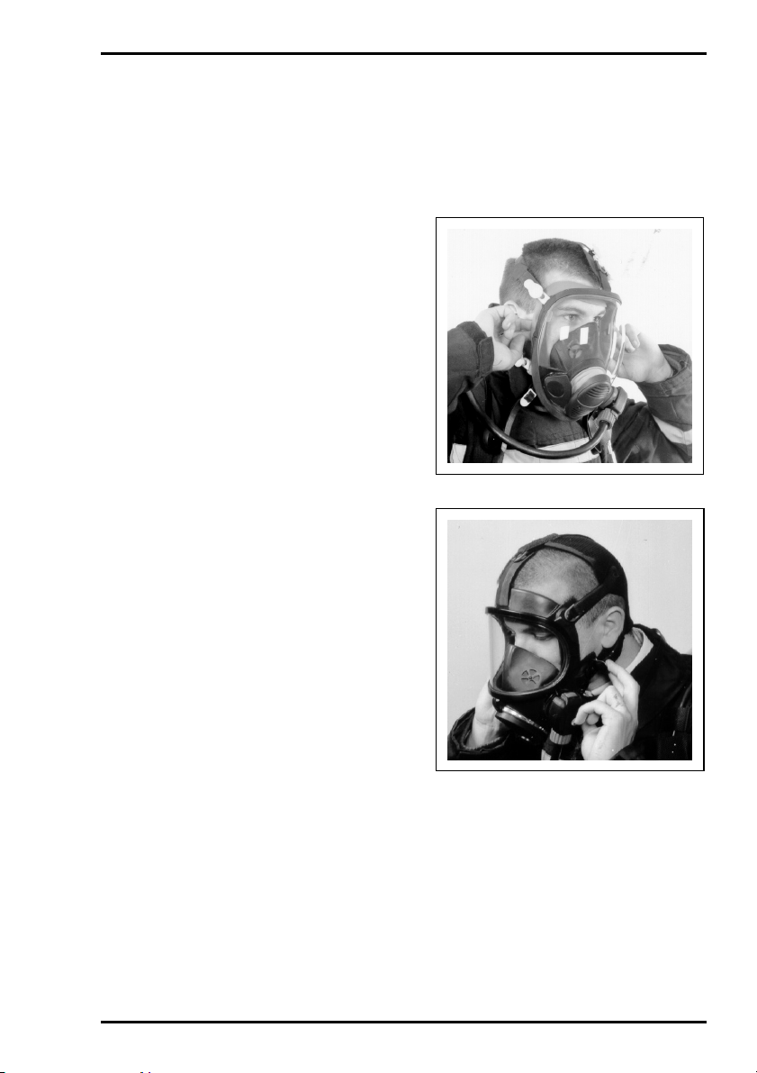
4.3.1 Facemasks with a Web Harness ............................................................................................................ 16
4.3.2 Facemasks with a Net Harness .............................................................................................................. 17
4.4 POSITIVE PRESSURE TEST .......................................................................................................................... 17
4.5 FACEMASK SEAL TEST ................................................................................................................................. 17
4.6 WHISTLE TEST ............................................................................................................................................... 18
4.7 FINAL CHECKS ............................................................................................................................................... 18
4.8 ATTACHING AN AIRLINE................................................................................................................................ 18
5. DOFFING INSTRUCTIONS ....................................................................................................................................... 19
5.1 DOFFING THE APPARATUS .......................................................................................................................... 19
5.2 REMOVE CYLINDER(S) .................................................................................................................................. 19
6. AFTER USE............................................................................................................................................................... 20
6.1 CLEANING ....................................................................................................................................................... 20
6.2 CHECK APPARATUS ...................................................................................................................................... 21
6.3 RECORD TEST DETAILS................................................................................................................................ 21
6.4 STORAGE........................................................................................................................................................ 21
7. SCHEDULED MAINTENANCE.................................................................................................................................. 22
7.1 MONTHLY........................................................................................................................................................ 22
7.2 ANNUALLY....................................................................................................................................................... 22
Registered Office: Scott Health and Safety Limited, Pimbo Road, West Pimbo,
Skelmersdale, Lancashire, WN8 9RA, England.

ii
WARNINGS
Please Read Carefully and Fully Understand
This manual is for use by personnel trained in the use and care of compressed air
breathing apparatus, and MUST NOT be used as a self-teaching guide by untrained users.
Failure to understand or adhere to the Pro-Pak user instructions may result in injury or
death.
Scott Health and Safety Limited have taken great care to ensure that the information in
this manual is accurate, complete and clear. However, Training and Technical Support
Services will be pleased to clarify any points in the manual and answer questions on
SCOTT breathing apparatus.
The following warnings are in accordance with certifying authority requirements and
apply to the use of breathing apparatus in general:
Breathing apparatus users must be fully trained in the use and care of self-
contained, compressed air breathing apparatus.
Ensure that the selection of the apparatus type is sufficient for the tasks
being undertaken and the hazards likely to be encountered. Please refer to
National Regulations for guidance.
Adequate protection may not be provided in certain highly toxic atmospheres.
The apparatus must be tested and serviced in accordance with Section 7 -
Scheduled Maintenance and the notes in Section 1 under Training &
Servicing.
The quality of air used to supply and charge breathing apparatus must meet
the requirements of EN 12021 : 1999 or AS/NZS1715 : 1994. See Section 1 for
details.
In Australia and New Zealand, ensure that your selection of respiratory
protective devices conform to the requirements of AS/NZS1715 : 1994.
Ensure that a good seal can be obtained between the face and facemask. The
wearing of beards, side-burns or spectacles may adversely affect the sealing
of a facemask to the wearer's face.
The apparatus is not designed for use underwater.
The harness must not be used as a vehicle seat restraint.
To decontaminate the equipment correctly in the event of exposure or risk of
exposure to any CBRN (Chemical, Biological, Radiological or Nuclear)
situation, please refer to your standard operating procedures.
DISCLAIMER
Failure to comply with these instructions or misuse of the apparatus may result in:
death, injury or material damage, and invalidate any warranty or insurance claims.
COPYRIGHT
This manual must not be copied in part or whole, or used for purposes other than its intended
purpose without the written permission of Scott Health and Safety Limited.

PRO-PAK
1
1. INTRODUCTION
1.1 ABBREVIATIONS
The following abbreviations are used in
this manual:
AL Airline Attachment
BA Breathing Apparatus
CVR Cylinder Valve Retainer
DCC Decontamination Attachment
DV Demand Valve
HP High Pressure
IRIS Integrated Radio Information
System
L/min Litres per Minute
m Metres
min Minutes
mg Milligrams
mm Millimetres
MP Medium Pressure
NRV Non Return Valve
PRV Pressure Relief Valve
psi Pounds per Square Inch
RSM Rescue Mask Attachment
1.2 BREATHABLE AIR
Air used to supply or charge breathing air
may be natural or synthetic. The
composition of breathable air is given in
Table 1.
Component Mass %
(Dry Air)
Volume%
(Dry Air)
Oxygen 23.14 20.948
Nitrogen 75.52 78.08
Argon 1.29 0.93
Carbon Dioxide 0.05 0.031 4
Hydrogen 0.000 003 0.000 05
Neon 0.001 270 0.001 818
Helium 0.000 037 0.000 524
Krypton 0.000 330 0.000 114
Xenon 0.000 039 0.000 009
Table 1: Breathable Air - EN 12021
(NOT applicable for Australia or New
Zealand)
There is an increased fire risk when the
oxygen content is above the value shown
above.
The purity/quality of air used to supply
and charge breathing apparatus should
be tested periodically in accordance with
national regulations.
Unless otherwise specified, the
contaminants shall not exceed the
permissible exposure level.
National regulations must be observed.
The mineral oil content shall be such that
the air is without the odour of oil. The
odour threshold is in the region of 0.3
mg/m3.
The water content shall not exceed 50
mg/m3for 200 and 207 bar apparatus and
30 mg/m3for 300 bar apparatus.
For airline apparatus, air must be used
with a dew-point sufficiently low to
prevent internal freezing.
1.3 COMPRESSED AIR
AIRLINE SUPPLIES
Air for use with compressed air airlines
must conform to EN 12021 : 1999 or
AS/NZS1715 : 1994 and must have a
dew point sufficiently low to prevent
internal freezing when apparatus is used
in temperatures below 4°C.
No. of Wearers Airflow (L/min.)
1
2
3
4
300
450
750
900
Table 2
Airline pressure must be between 5.0 and
9.0 bar (70 and 130 psi). Airflow supply
capacity for a single airline is given in
Table 2.
Generally; each additional wearer
requires an extra 150 litres per minute,
each additional pair of wearers requires
300 L/min for one wearer and 450 L/min
for two wearers. All measurements must
be taken at the wearer end of the airline.
Example: for 8 users (4 pairs) the
recommended flow is 4 x (300 + 150) =
1800 litres per minute.
An airline flow tester is available from
Scott Health and Safety Limited under
Article Number 1035978.

PRO-PAK
2
Compressed air airlines used with Pro-
Pak must be SCOTT products, approved
to EN 139 or AS/NZS1716 : 2003.
Ensure that hoses used in an explosive or
flammable atmosphere are marked:
ANTI-STATIC
EN 139
AS/NZS1716
BREATHING AIR
Cost effective PVC hoses may be used in
other atmospheres.
Scott Health and Safety Limited
manufacture a range of anti-static and
PVC hoses, in lengths ranging from 15m
to 60m. Our Customer Services
Department will be pleased to advise on
price and delivery.
1.4 APPARATUS DURATION
All durations quoted are nominal, based
on an Average Wearer Consumption
Rate of 40 L/min and FULLY CHARGED
cylinders. Actual Wearer Consumption
rates vary due to many factors, such as:
•Workload: high work rates increase
consumption rates.
•Weight of apparatus and use of
heavy or restrictive clothing.
•Work environments with extremes
of heat or cold.
•Physical fitness of the wearer.
•Other factors include emotional
stress and fatigue.
•Supplying cylinder air to a
resuscitator or rescue second mask
(RSM).
It is important that all wearers are aware
of these factors and take account of them
when assessing cylinder duration.
1.5 PERSONNEL TRAINING
Personnel who use self-contained,
compressed air breathing apparatus must
be fully trained in accordance with these
instructions and national regulations.
These instructions cannot replace an
accredited training course run by fully
qualified instructors in the proper and
safe use of SCOTT breathing apparatus.
Please contact Training and Technical
Support Services or your distributor for
training course details.
Training and Technical Support
Services:
Scott Health and Safety Limited
Pimbo Road, West Pimbo,
Skelmersdale, Lancashire,
WN8 9RA, England.
Tel: +44 (0) 1695 711711
Fax: +44 (0) 1695 711775
1.6 SERVICING
Pro-Pak must be serviced at scheduled
intervals by personnel who have
completed a formal training course and
hold a current certificate for the servicing
and repair of SCOTT breathing
apparatus. Details of the servicing
schedule are contained in the SCOTT
Pro-Pak Service Manual, copies of which
can only be obtained by registered
holders of a current certificate.
Your distributor or Training and
Technical Support Services will be
pleased to provide training course details
and quotes for service contracts. Please
see above for contact details.
1.7 SPARE PARTS AND
ACCESSORIES
Customer Services provide an efficient,
friendly, customer contact point for
ordering new apparatus, spare parts and
accessories. The team can also provide
general information on SCOTT products.
Customer Services:
Scott Health and Safety Limited
Pimbo Road, West Pimbo,
Skelmersdale, Lancashire,
WN8 9RA, England.
Tel: +44 (0) 1695 711711
Fax: +44 (0) 1695 711775

PRO-PAK
3
1.8 WARRANTY
The products manufactured at our
factories in Skelmersdale and Vaasa
carry a warranty of 12 months (unless
stated otherwise) for parts, labour and
return to site. The warranty period runs
from the date of purchase by the end
user.
These products are warranted to be free
from defects in materials and
workmanship at the time of delivery.
SCOTT will be under no liability for any
defect arising from wilful damage,
negligence, abnormal working conditions,
failure to follow the original
manufacturer’s instructions, misuse or
unauthorised alteration or repair.
Evidence of purchase date will need to be
provided for any claims arising during the
warranty period. All warranty claims must
be directed through SCOTT Customer
Services and in accordance with our
sales return procedure.
1.9 NOTIFIED BODIES
Inspec International Ltd (0194)
56 Leslie Hough Way,
Salford,
Greater Manchester,
M6 6AJ,
England.
British Standards Institute (0086)
389 Chiswick High Road,
London,
W4 4AL,
England.
SAI Global
286 Sussex Street,
Sydney,
NSW 2000,
Australia.
Lic. No 1214.
2. APPARATUS
DESCRIPTION
2.1 GENERAL
Pro-Pak is an open circuit, self-
contained, compressed air Breathing
Apparatus (BA) for use by fire-fighters
and in industrial applications where a high
level of respiratory protection is required.
Standard versions of Pro-Pak feature a
mechanical pressure gauge and whistle
mounted on the left-hand shoulder strap.
Versions specifically intended for use by
fire-fighters are available which
incorporate the IRIS data-
communications system.
Pro-Pak is approved to the following
European Standards:
•EN 137 : 2006 - Including Annex A,
Self-contained Breathing Apparatus
classification: Type 2 - Fire
Fighting.
•EN 139 : 1995 - Self-contained
Breathing Apparatus with airline
attachment when there is no
intermediate split connection in the
MP airline between DV and
Pressure Reducer.
•EN 139 : 1995 - Excluding
requirements of clause 6.7.2, Self-
contained Breathing Apparatus with
airline attachment when there is an
intermediate split connection in the
MP airline between DV and
Pressure Reducer.
Pro-Pak is 'CE' marked in accordance
with EEC Directive EC/686/1986 plus
amendments.
Pro-Pak is approved to Australian/New
Zealand Standard AS/NZS1716 : 2003.
Please call Scott Health and Safety
Limited for further apparatus approval
details.
This manual contains user instructions for
single cylinder, twin cylinder (Duo)
versions and versions for use with
compressed air airlines.

PRO-PAK
4
Pro-Pak is marked in accordance with
EN 137 : 2003 and AS/NZS1716 : 2003.
An explanation of those markings is given
below:
Key Meaning
A = Product brand name
B = Symbol - refer to User Instructions
C = Product model/designation
D = Apparatus description
E = Standards to which apparatus is certified
F = Number of Approval Body
G = Serial number of apparatus
H = Date of manufacture
I = Contact details of manufacturer
2.2 HARNESS
The Pro-Pak harness is made from
flame-retardant KevlarTM and NomexTM.
The buckles are manufactured from
stainless steel, chromium-plated steel or
brass; and the press-studs from brass or
nickel-plated brass.
For wearer comfort, a lumbar pad or full
back pad is provided. Both are fabricated
from flame-retardant material and packed
with flame retardant, closed cell foam.
The lumbar pad is held in place by four
press-studs. The full-length pad is held by
press studs and the harness straps.
2.3 CYLINDER BAND
Pro-Pak can be configured for use with
one or two (Duo) 200, 207 or 300 bar,
steel or fully wrapped aluminium carbon
fibre composite cylinders (see Table 3).
Cylinders are secured to the lightweight
back-plate by a webbing cylinder band
and a cylinder valve retainer (CVR).
The webbing cylinder band is secured
around the cylinder(s) by a hinged, clamp
mechanism with a thumb-operated
release tag that prevents accidental
opening. The band can be adjusted to
accept the range of cylinders listed in
Table 3. The clamp mechanism facilitates
replacement of similar size cylinders
without cylinder band adjustment.
Pro-Pak Duo cylinder bands can easily
be altered by the wearer (no tools
required) to mount a single cylinder,
centrally on the back-plate.
2.4 THE PNEUMATIC
SYSTEM
The pneumatic system has two pressure
reduction stages: air from the cylinder is
reduced to a medium-pressure (MP) of
between 5.5 and 11 bar by the reducer.
The second pressure reduction is
performed in the facemask Demand
Valve (DV).
Air from the cylinder passes through a
sintered bronze particle filter in the
cylinder connector, which protects the
pneumatic system, then through a short
length of high-pressure (HP) braided
hose to the reducer inlet manifold.

PRO-PAK
5
Weight of Pro-Pak
with Cylinder
(kg)
Cylinders Water
Capacity
(litres)
Charging
Pressure
(bar)
Free air
Volume
(litres)
Nominal
Duration
(min)
Warning
Period
(min)
Total
Duration
(min)
Cylinder
Charged
Weight
(kg) Single Duo
CYL-1200 6.0 200 1200 22 8 30 8.8 12.0
-
CYL-HWG-
1200 6.0 207 1200 22 8 30 7.2 10.4
-
CYL-FWC-
1300 4.7 300 1300 25 7 32 5.0 8.2
-
CYL-1640 6.0 300 1640 33 8 41 12.5 15.7
-
CYL-HWG-
1640 6.0 300 1640 33 8 41 10.0 13.2
-
CYL-FWC-
1640 6.0 300 1640 33 8 41 6.3 9.5 16.0
CYL-1800 9.0 200 1800 33 12 45 13.0 16.2
-
CYL-HWG-
1800 9.0 207 1800 33 12 45 11.2 14.4
-
CYL-FWC-
1800 9.0 207 1800 33 12 45 6.75 9.95 18.0
CYL-FWC-
1860 6.8 300 1860 37 9 46 6.75 9.95 18.0
CYL-FWC-
2460 9.0 300 2460 50 12 62 8.8 12.0
-
Note: Only cylinders in the shaded areas (above) are suitable for use with Pro-Pak Duo in
the twin-cylinder configuration. The total apparatus weight must not exceed 18 kg when fully-
charged; (ref: EN 137, Clause 5.4 and AS/NZS1716 : 2003).
Table 3: Cylinders approved for use with Pro-Pak apparatus
Table 4 identifies the cylinder material code and cylinder specification.
Code Material Specification
No Code Steel (e.g.: CYL-1200) CE Marked (EU)
Work Cover (Australia & New Zealand)
HWG Hoop Wrapped Glass Fibre (e.g.: CYL-HWG-1200) HSE-AL-HW1 (EU)
Work Cover (Australia & New Zealand)
FWC Fully Wrapped Carbon (e.g.: CYL-FWC-1300) CE Marked (EU)
Work Cover (Australia & New Zealand)
Table 4: Cylinder Codes and Specifications
Durations are nominal and based on an Average Wearer Consumption Rate of 40 L/min and
are for fully charged cylinders.
Cylinder Free Air Capacity
Total Duration = Average Wearer Consumption Rate
Nominal Duration = Total Duration minus the Warning Period.
Whistle Operating Pressure
Warning Period = Average Wearer Consumption Rate

PRO-PAK
6
2.5 REDUCER
The reducer is a simple, self-regulating,
spring and piston device that requires no
adjustment. It has a pressure relief valve
(PRV) that protects the MP system from
over-pressurisation.
Air from the reducer is connected through
a reinforced, chlorinated polyethylene
hose to the facemask-mounted DV, which
regulates the air supplied to the wearer.
2.6 GAUGE AND WHISTLE
A high-pressure hose from the reducer
inlet manifold connects air, at cylinder
pressure, to a warning whistle and
pressure gauge.
On standard versions, the warning whistle
and pressure gauge are mounted on the
left-hand shoulder strap. On versions
fitted with the IRIS data-communications
system, the warning whistle and pressure
gauge are incorporated within the IRIS
unit.
The warning whistle sounds when
pressure in the cylinder falls to 55 bar (±5
bar).
The duration of the air remaining in the
cylinder, from the start of the warning
whistle, is listed for each cylinder type
under Warning Period in Table 3.
The pressure gauge dial is photo
luminescent to aid use in low light levels.
The lens is impact resistant
polycarbonate. A rubber shroud protects
the gauge.
Should the gauge, whistle or hose
become damaged, a restrictor in the
reducer limits air-loss to less than 25
litres per minute.
2.7 DEMAND VALVE
The DV operates in conjunction with the
facemask spring loaded exhale valve to
maintain a positive pressure within the
facemask.
The DV has a servo-assisted tilting
diaphragm mechanism that responds to
pressure changes within the facemask to
regulate the flow of air to the mask,
ensuring that pressure within the mask
remains safely above ambient.
The DV has a reset button that enables
wearers to close the airflow through the
DV, permitting the facemask to be
removed during test procedures and at
the end of a task, without loss of cylinder
air.
When the apparatus is donned the DV is
normally ‘reset’ (closed), and is opened
(activated) when the wearer takes a first
breath.
The DV has a supplementary flow device
(bypass), that the wearer can open using
the bypass knob.
When the bypass is used, the
unregulated flow of air through the DV
reduces cylinder duration.
The DV is connected to the facemask by
a Quick-Fit (QF) bayonet fitting with a
spring-loaded locking catch to prevent
accidental disconnection.

PRO-PAK
7
2.8 OPTIONAL
ATTACHMENTS
The available options are:
•Decontamination attachment (DCC)
- facilitates airline connection into a
gas-tight chemical suit, permitting
the wearer to breathe from an
airline during extended
decontamination procedures.
•Rescue mask attachment (RSM) -
permits the wearer to supply a
rescue mask or an air-powered
resuscitator from own cylinder air.
This reduces the duration of the
cylinder supply.
•Airline attachment (AL) - permits
Pro-Pak to be used with an airline.
The cylinder provides emergency
backup.
Note:
Air for use with airlines must conform to
Breathable Air as detailed in Section 1.
2.9 FACEMASKS
Pro-Pak is approved for use with:
Vision 3, PanaSeal, PanaVisor and
Promask PP full facemasks, all of which
conform to EN 136, Class 3 and
AS/NZS1716 : 2003.
All are available with five point, fully
adjustable web or net head-harnesses
and neck-straps.
An inner mask minimises CO2dead
space and visor misting. A speech
diaphragm is fitted.
PanaSeal is suitable for medium and
smaller face sizes. PanaVisor is suitable
for medium to larger face sizes.
Vision 3 is available in three sizes: small,
medium and medium/large which cover
most face sizes. Promask PP is available
in two sizes: small/medium and
medium/large.
Vision 3 is moulded in grey silicone,
while PanaSeal and PanaVisor are of
non-dermatitic, black neoprene or blue
silicone. Promask PP is moulded in
hypo-allergenic, black ProcompTM with a
soft silicone inner mask.
The polycarbonate visors conform to EN
166 Grade B for medium impact-
resistance and AS/NZS 1337: 1992 for
high-impact resistance.
Versions of the above masks are also
available with helmet attachment clamps
fitted. Please contact Customer Services
for further information.
Vision 3 Facemask with Web Harness
PanaSeal/PanaVisor Facemask with
Net Harness

PRO-PAK
8
Promask PP Facemask
3. PRE-USE AND
MONTHLY CHECKS
3.1 CHECK APPARATUS
Visually inspect to ensure that Pro-Pak is
clean and in good condition. Check that
all hose retaining press-studs or VelcroTM
retainers are closed. Fully slacken the
waist-belt and shoulder straps ready for
use.
When Pro-Pak is to be used with an
airline check that:
i) The airline is in good condition, free
from splits, bulges and abrasions.
ii) The airline connector is in good
condition and that it connects securely to
the Pro-Pak pigtail.
iii) The air-supply conforms to EN
12021 or AS/NZS1715 : 1994 (see
Section 1.3 - Compressed Air Airline
Supplies).
iv) The Pro-Pak airline coupling is in
good condition.
3.2 REPLACING SINGLE
CYLINDERS
1. Close the cylinder valve.
2. Open the facemask bypass to vent
the system.
3. Unscrew the cylinder connector.
4. Use the thumb of your right hand to
push the release tag away from the clamp
mechanism in the direction of the arrow
that appears on the moulded clamp
cover. The clamp mechanism will open,
allowing the cylinder to move freely within
the cylinder band.

PRO-PAK
9
5. Remove the cylinder by sliding it
through the loosened cylinder band in
either direction, as desired.
CAUTION:
Before installing a cylinder onto the
back-plate, ensure that the protective
edge strip is in position on the buckle
pivot bracket.
6. Slide a fully-charged cylinder along
the back-plate and through the loosened
cylinder band. Position the cylinder valve
outlet through the cylinder valve retainer.
7. Apply gentle pressure to the clamp
mechanism by pushing downwards and
toward the cylinder to close the
mechanism and tighten the cylinder band.
The clamp mechanism will lock
automatically when closed.
8. Check that the cylinder hand-wheel
connector O-ring is clean and in good
condition. Screw the cylinder connector
firmly into the cylinder valve outlet.
Should it become necessary to adjust the
size of the cylinder band:
i) Ensure that the clamp mechanism
is unlocked and in the open position.
ii) Adjust the tension of the cylinder
band using the slide buckle.
iii) Close the clamp mechanism and
check that the cylinder is held securely.
Repeat as necessary.
3.3 REPLACING DUO
CYLINDERS
1. Close both cylinder valves.
2. Open the facemask bypass to vent
the system.
3. Undo both cylinder connectors.
4. Use the thumb of your right hand to
push the release tag away from the clamp
mechanism in the direction of the arrow
that appears on the moulded clamp
cover. The clamp mechanism will open,
allowing the cylinder nearest to the clamp
to move freely within the cylinder band.
5. Remove the freed cylinder by
sliding it through the loosened cylinder
band in either direction, as desired.

PRO-PAK
10
6. Manoeuvre the cylinder valve end
of the remaining cylinder to allow removal
of the Duo manifold from the cylinder
valve retainers.
7. Place the Duo manifold and high-
pressure hose aside, away from the
remaining cylinder valve.
8. Holding the flag-end loop and
cylinder band together, feed through the
buckle on the cylinder dividing loop. The
cylinder will move freely within the
cylinder band.
9. Remove the cylinder by sliding it
through the loosened cylinder band in
either direction, as desired.
WARNING:
Replacement cylinders must always be
fully-charged and of matching types.
CAUTION:
Before installing cylinders, ensure that
the protective shrouds are in position
on the buckle pivot bracket.
Note:
Cylinder replacement is carried out in the
reverse order of removal - i.e.: the last to
be removed is the first to be replaced.
10. Slide a fully-charged cylinder along
the back-plate and through the loosened
cylinder band. Position the cylinder outlet
through the cylinder valve retainer.
11. Inspect the cylinder connector O-
Rings on the Duo manifold to ensure that
they are clean and in good condition.
12. Manoeuvre the cylinder valve end
of the cylinder to allow the Duo manifold
to be inserted through the cylinder valve
retainers.
13. Holding the flag-end loop and
cylinder band together, re-feed through
the buckle on the cylinder dividing loop.
The cylinder will be loosely held within the
cylinder band.
14. Screw the cylinder connector firmly
into the cylinder valve outlet.
15. Slide a second fully-charged
cylinder along the back-plate and through
the loosened cylinder band. Position the
cylinder outlet through the cylinder valve
retainer.
16. Screw the cylinder connector firmly
into the cylinder valve outlet on the
second cylinder.

PRO-PAK
11
17. Grasp the cylinder band near to the
slide buckle and pull firmly to securely
retain the cylinder furthest from the clamp
mechanism.
18. Apply gentle pressure to the clamp
mechanism by pushing downwards and
toward the cylinder to close the
mechanism and tighten the cylinder band.
The clamp mechanism will lock
automatically when closed.
Should it become necessary to adjust the
size of the cylinder band:
i) Ensure that the clamp mechanism
is unlocked and in the open position.
ii) Adjust the tension of the cylinder
band using the slide buckle.
iii) Repeat operations 17 and 18 and
check that both cylinders are held
securely. Repeat as necessary.
19. Re-confirm that both cylinder
connectors are firmly secured to the
cylinder valve outlets.
3.4 CONVERTING FROM
DUO CYLINDERS TO
SINGLE CYLINDER
Pro-Pak Duo can be adapted to
accommodate either one or two cylinders.
Conversion is a straightforward process
in which no tools are required.
To convert from Duo to single cylinder
application:
1. Remove both cylinders from the
back-plate as described in Section 3.3 of
this Manual.
2. Unscrew the central cylinder
connector from the Duo manifold. Store
the manifold safely for future use when
the Duo application may be required once
again.
3. Place the folding cylinder valve
retainer flat against the back-plate.
4. Rotate the fixed cylinder valve
retainer through 180o.
5. Remove the cylinder band loop (A)
from the retaining bracket by squeezing
together the end of the loop with the
thumb and forefinger and manoeuvring to
withdraw from the open-ended bracket.
6. Attach the flag-end loop (B) to the
retaining bracket by fitting one side of the
loop over the bracket and manoeuvring
until the opposite side of the loop is also
correctly positioned. Ensure that the loop
is fitted securely.

PRO-PAK
12
7. Pass the excess cylinder band
between the back-plate and back-pad, at
the point where the centre-straps retain
the pad to the back-plate.
8. Route the cylinder band around the
back-pad and insert the end of the band
between the back-plate and back-pad.
9. Ensure that the redundant cylinder
dividing loop (arrowed) lies flat against
the back-plate, in preparation for single
cylinder fitment.
10. Fit a single cylinder as described in
Section 3.2 of this Manual.
To convert from single cylinder to Duo
cylinders, carry out the reverse of the
above sequence of operations.
3.5 RESET DEMAND VALVE
1. Press the black rubber reset button
on the side of the DV and check that the
red bypass knob is turned so that the flat
on the bypass knob aligns with the DV
outlet.
2. Check that the orange O-ring on
the DV outlet is clean and in good
condition.
3.6 CYLINDER PRESSURE /
LEAK TEST
1. Slowly open cylinder valve fully and
allow 10 seconds for the apparatus to
pressurise.
2. Check that the pressure gauge
shows the cylinder is at least 80% FULL
(240 bar for 300 bar cylinders, 170 bar for
200 and 207 bar cylinders). Listen for
leaks.

PRO-PAK
13
3. Close the cylinder valve and
monitor the pressure gauge for one
minute. If the reading falls by more than
10 bar during this time there is an
unacceptable leak.
4. If the system fails the leak test:
close the cylinder valve, vent air from the
system by opening the DV bypass. Check
all pneumatic connections and repeat the
leak test.
5. DO NOT USE apparatus that leaks
excessively. Attach an explanatory note
and return the apparatus for service.
3.7 DV AND FACEMASK
3.7.1 All Facemasks
1. Check that the facemask is clean
and undamaged.
2. Check that the orange O-ring on
the DV outlet is clean and in good
condition.
3. Fit the DV to the facemask and
check that the red locking catch engages
fully. Twist the DV gently to confirm that it
has.
4. Fully open the cylinder valve.
3.7.2 Facemasks with a Web
Harness
1. Hold the head-harness lower
straps, place chin in chin-cup and pull
straps over back of head, brushing back
hair from under face-seal.
2. Tighten harness straps in
sequence: Bottom, Middle, Top. DO
NOT over-tighten.
3. Inhale deeply and check that the
DV first breath mechanism operates.

PRO-PAK
14
3.7.3 Facemasks with a Net
Harness
1. Hold the mask by the side of the
net harness, place the chin into the chin-
cup and pull the mask onto the face.
Grasp the pull-strap at the rear of the net
harness and pull the net over the head.
2. Tighten harness side straps. DO
NOT over-tighten.
3. Inhale deeply and check that the
DV first breath mechanism operates.
3.8 POSITIVE PRESSURE
TEST
1. With the cylinder valve open, insert
a finger under face-seal and check for a
steady outward flow of air. Remove finger
and allow mask to re-seal.
2. Hold breath for ten seconds and
listen for leaks. If there are leaks, loosen
the head-harness and adjust the mask for
a comfortable leak-tight fit and repeat
test. DO NOT over-tighten the head-
harness.
3. DO NOT USE apparatus that leaks.
Attach an explanatory note and return for
service.
4. When satisfied with the apparatus,
press the DV reset knob, remove the
facemask and close the cylinder valve.

PRO-PAK
15
3.9 WHISTLE TEST
1. With the cylinder valve closed,
open the bypass knob briefly to vent air
from the system.
2. Check that the whistle sounds
clearly as the pressure gauge falls below
55 bar (±5 bar).
3. The apparatus is now fully tested
and may be stored prior to use.
3.10 AIRLINE AND
DECONTAMINATION
ATTACHMENTS
1. Check the supply airline flow and
pressure. Remove connector dust caps
and check for wear and damage.
2. Make connection to an appropriate
connector capable of supplying
breathable compressed air (see Section
1.3 - Compressed Air Airline Supplies).
3. Check that the connection is secure
and that the connector releases easily,
without sticking.
4. Press the DV reset button.
5. Pressurise the attachment and
check all connections for leaks. Ensure
that the female connector on the airline
attachment does not leak.
6. DO NOT use attachments that
show signs of excessive wear or damage,
or that leak excessively.
7. Replace dust caps.
3.11 RSM ATTACHMENTS
1. Remove RSM dust caps and attach
a rescue mask to the RSM attachment.
2. Press the DV reset buttons on the
wearer facemask and rescue mask.
3. Open the Pro-Pak cylinder valve
and check that the RSM connection does
not leak.
4. Don the rescue mask, inhale
sharply to activate the first breath
mechanism and check that there is a
plentiful supply of air.
5. Disconnect the rescue mask and
check once again that the RSM connector
does not leak.
6. Replace dust caps.
7. DO NOT use attachments that
show signs of excessive wear or damage,
or that leak excessively.
3.12 HOSES
1. Check all hoses for damage and
excess wear. Flex hoses to reveal any
splits, cracks or crazing (minor crazing is
acceptable).
2. Check couplings for damage and
excess wear; and ensure that they can be
opened.
3. When closed, check that they form
a secure coupling.
4. Replace damaged or worn hoses.

PRO-PAK
16
4. DONNING
PROCEDURE
4.1 DON APPARATUS
Note:
Specialist Users (such as Emergency
Services) may operate alternative
donning procedures that conform to the
relevant statutory regulations and have
been approved by Scott Health and
Safety Limited.
1. Check that the Pro-Pak and
facemask harnesses are fully slackened
and that the DV is connected to the
facemask.
2. Hang the facemask round the neck
by its neck-strap.
3. Pass the right arm through the
shoulder strap and swing the harness
across the back and slip the left arm
through the shoulder strap.
4. Pull down on the shoulder strap
ends until the apparatus fits comfortably
then close the waist-belt and tighten the
slide buckle.
Note:
If the waist-belt is closed first, tightening
the shoulder straps will pull up the waist-
belt, causing discomfort.
4.2 CHECK DV / OPEN
CYLINDER VALVE
1. Check that the flat on the DV
bypass knob aligns with the DV outlet and
press the black reset button.
2. Open the cylinder valve slowly with
your right hand, whilst holding the
pressure gauge in your left (on Duo Sets,
open only one cylinder valve). Check that
the pressure gauge reads 80% FULL
(170 bar for 200 and 207 bar cylinders
and 240 bar for 300 bar cylinders).
WARNING:
When opening a cylinder valve, DO
NOT use the high-pressure hose as
leverage.
4.3 DON FACEMASK
4.3.1 Facemasks with a Web
Harness

PRO-PAK
17
1. Hold the head-harness lower
straps, place chin in chin-cup and pull
straps over back of head, brushing hair
away from face-seal.
2. Adjust the facemask top strap so
that the mask is at the correct level with
the face and the head-harness pad is in
the centre of the back of the head, then
tighten harness straps in sequence:
Bottom, Middle, Top. DO NOT over-
tighten.
3. Inhale deeply to activate the DV
then breathe normally.
4.3.2 Facemasks with a Net
Harness
1. Hold the mask by the side of the
net harness, place the chin into the chin-
cup and pull the mask onto the face.
Grasp the pull-strap at the rear of the net
harness and pull the net over the head.
2. Tighten harness side straps. DO
NOT over-tighten.
3. Inhale deeply to activate the DV
then breathe normally.
4.4 POSITIVE PRESSURE
TEST
1. With the cylinder valve open, insert
a finger under face-seal and check for a
steady outward flow of air. Remove finger
and allow mask to re-seal.
4.5 FACEMASK SEAL TEST
1. Close the cylinder valve and keep
hold of the hand-wheel. Hold breath for
10 seconds and listen carefully for leaks.
A leak will cause the pressure gauge
reading to fall.
2. If the facemask fails the leak test:
open the cylinder valve, loosen the head-
harness adjust the facemask and repeat
the test.
Other manuals for PRO-PAK
1
Table of contents
Other Scott Diving Instrument manuals

Scott
Scott FLITE User manual

Scott
Scott AIR-PAK 75i 2.2 Installation and operation manual

Scott
Scott Contour User manual

Scott
Scott 2.2 Installation and operation manual

Scott
Scott SCOTT AIR-PAK NxG2 Installation and operation manual

Scott
Scott PRO-PAK User manual

Scott
Scott AIR-PAK 75 Installation and operation manual
Popular Diving Instrument manuals by other brands

Kirby Morgan
Kirby Morgan KM 97 installation instructions

Kirby Morgan
Kirby Morgan SuperFlow 525-757 manual

Aqua Lung
Aqua Lung AIRSOURCE 3 owner's manual

Blueprint Subsea
Blueprint Subsea ArtemisPRO Quick reference guide

Essex Electronics
Essex Electronics MR-100 User Reference and Procedures Manual

SKYTRONIC
SKYTRONIC GFX user manual