Waste electrical products should not be disposed of
with household waste.
Please recycle where facilities exist.
Check with your local authority for recycling advice.
Variable Signal Booster x 1
‘F’ to Coaxial Flylead x 1
12/24V fused power cable x 1
Screw x 2
Screw Cap x 2
‘F’ Connector x 2
A:
B:
C:
D:
E:
F:
A
B
PACK CONTENTS
D
E
F
Installation instructions inside
No picture on TV
■ Check amplifier LED is on
■ Check coaxial cable connections
■ Adjust gain of amplifier
■ TV or set top box not tuned in
■ Poor reception area
Picture breaks up or freezes
■ Adjust gain of amplifier
■ Poor reception
Power LED does not illuminate when power is switched on
■ No power, check other devices on same electrical circuit
■ Fuse has blown
Waste electrical products should not
be disposed of with household waste.
Please recycle where facilities exist.
Check with your local authority for
recycling advice.
9111298 Iss 1
A A
B
C
D
EFGH
■Helpline: +44 (0) 1553 811000
■Email: cust_serv@maxview.co.uk
■Visit: www.maxview.co.uk
Maxview Reserve the right to change
specifications without prior notice
FAULT FINDING
2 YEAR GUARANTEE
CONNECTIONS & FEATURES
A:
B:
C:
D:
E:
F:
G:
H:
Wall fixing hole
On/off power switch
LED power indicator
Gain control knob
12/24V power input
Antenna input
TV/Radio output
TV/Radio output
SAFETY WARNINGS
■This booster is only suitable for vehicles with a negative chassis earth
■Disconnect battery before starting installation
■To avoid injury always route cables or wiring carefully
■Always follow manufacturer’s operating and safety instructions before
using tools and/or equipment
■Do not install appliance where it could be exposed to water or moisture
■For indoor use only
■If in doubt consult a qualified electrician or professional aerial installer
C
SPECIFICATIONS
Fuse Type: 2A F type 1 1/4”x dia 1/4”
Frequency Range (MHz): 40-860
Channels: 2-69
Gain control: 0-18dB
Input Power: 12-24V x 50mA DC
Noise: <4dB
Designed for
continuous use
Designed for
indoor use only
This signal booster is guaranteed against defective parts or
workmanship for 2 years from time of purchase. This excludes any
malfunction caused be improper use, accidental or malicious
damage or removal of the outer casing. This does not affect your
statutory rights.
TO
AERIAL
EXTRA TV/RADIO
OUTPUT IF REQUIRED
POWER CONNECTION
RED +12/24V BLACK 0V
TO TV ‘F’
COAXIAL
FLYLEAD
12/24V FUSED CONNECTION
ON
1. Slide power switch to right. LED indicator should now be on.
2. Turn gain control knob clockwise to increase signal strength.
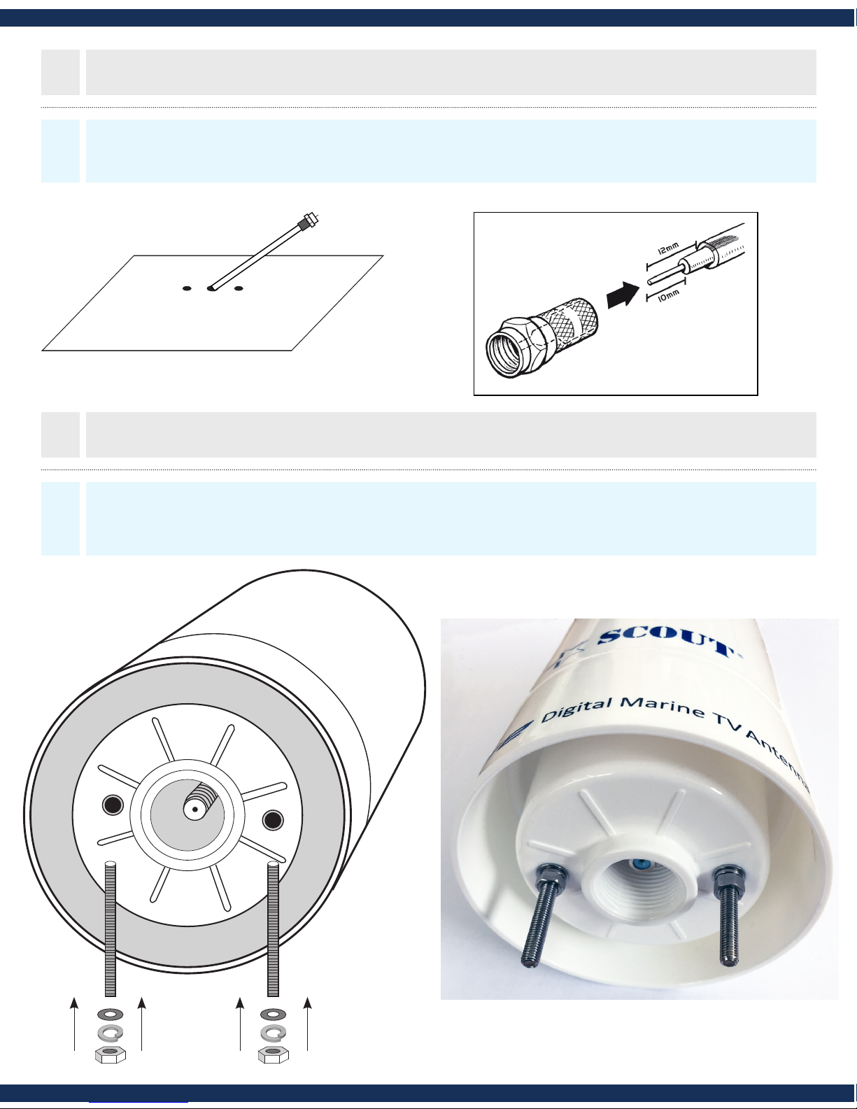
10mm
12mm
1
2
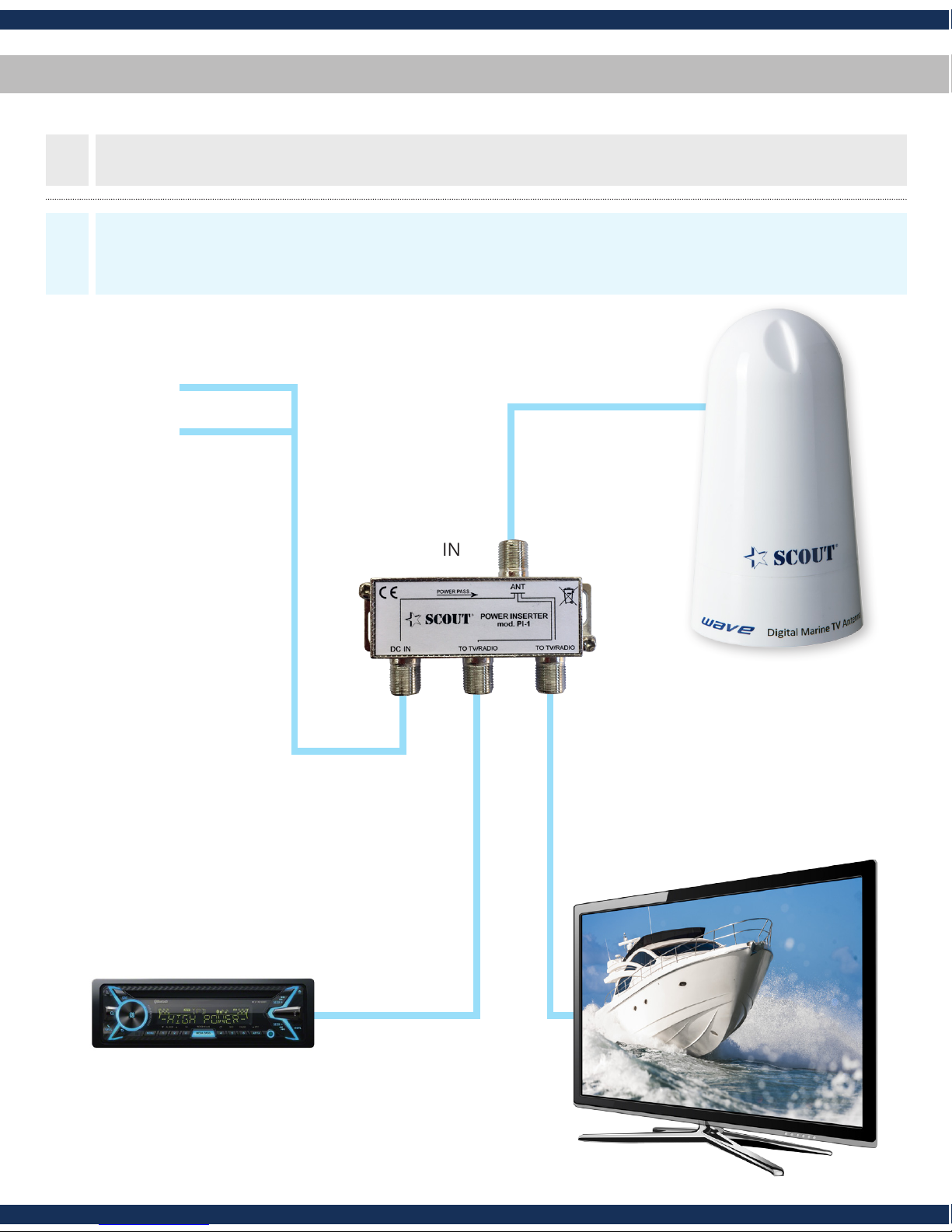
CONNECTION DIAGRAM
FITTING ‘F’ CONNECTOR
MOUNTING OPTIONS
OPERATION
THIS SECTION
NEEDS TO BE
VISIBLE IN
BLISTER CAVITY.
see example
Variable Signal Booster x 1
‘F’ to Coaxial Flylead x 1
12/24V fused power cable x 1
Screw x 2
Screw Cap x 2
‘F’ Connector x 2
A:
B:
C:
D:
E:
F:
A
B
PACK CONTENTS
D
E
F
Installation instructions inside
No picture on TV
■ Check amplifier LED is on
■ Check coaxial cable connections
■ Adjust gain of amplifier
■ TV or set top box not tuned in
■ Poor reception area
Picture breaks up or freezes
■ Adjust gain of amplifier
■ Poor reception
Power LED does not illuminate when power is switched on
■ No power, check other devices on same electrical circuit
■ Fuse has blown
Waste electrical products should not
be disposed of with household waste.
Please recycle where facilities exist.
Check with your local authority for
recycling advice.
9111298 Iss 1
A A
B
C
D
EFGH
■Helpline: +44 (0) 1553 811000
■Email: cust_serv@maxview.co.uk
■Visit: www.maxview.co.uk
Maxview Reserve the right to change
specifications without prior notice
FAULT FINDING
2 YEAR GUARANTEE
CONNECTIONS & FEATURES
A:
B:
C:
D:
E:
F:
G:
H:
Wall fixing hole
On/off power switch
LED power indicator
Gain control knob
12/24V power input
Antenna input
TV/Radio output
TV/Radio output
SAFETY WARNINGS
■This booster is only suitable for vehicles with a negative chassis earth
■Disconnect battery before starting installation
■To avoid injury always route cables or wiring carefully
■Always follow manufacturer’s operating and safety instructions before
using tools and/or equipment
■Do not install appliance where it could be exposed to water or moisture
■For indoor use only
■If in doubt consult a qualified electrician or professional aerial installer
C
SPECIFICATIONS
Fuse Type: 2A F type 1 1/4”x dia 1/4”
Frequency Range (MHz): 40-860
Channels: 2-69
Gain control: 0-18dB
Input Power: 12-24V x 50mA DC
Noise: <4dB
Designed for
continuous use
Designed for
indoor use only
This signal booster is guaranteed against defective parts or
workmanship for 2 years from time of purchase. This excludes any
malfunction caused be improper use, accidental or malicious
damage or removal of the outer casing. This does not affect your
statutory rights.
TO
AERIAL
EXTRA TV/RADIO
OUTPUT IF REQUIRED
POWER CONNECTION
RED +12/24V BLACK 0V
TO TV ‘F’
COAXIAL
FLYLEAD
12/24V FUSED CONNECTION
ON
1. Slide power switch to right. LED indicator should now be on.
2. Turn gain control knob clockwise to increase signal strength.
10mm
12mm
1
2
CONNECTION DIAGRAM
FITTING ‘F’ CONNECTOR
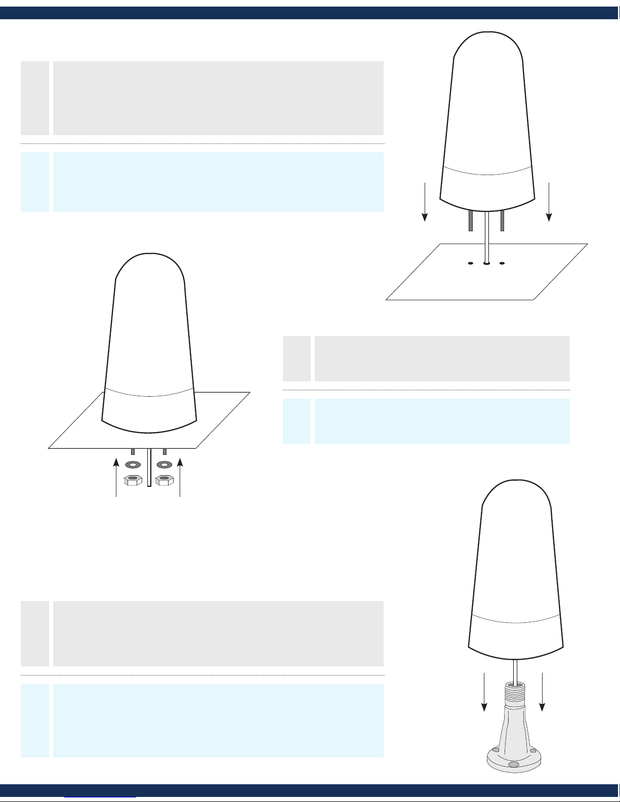
MOUNTING OPTIONS
OPERATION
THIS SECTION
NEEDS TO BE
VISIBLE IN
BLISTER CAVITY.
see example
Technical specications - Speciche tecniche
Support, Terms & Conditions - Supporto
Reception Omnidirectional
Frequency Range 40-860 MHz
Impedance 75 ohm
Channels 1-69
Gain 25 dB
Input power 12V DC
Noise gure 0.2 dB
Output 2
Connectors F
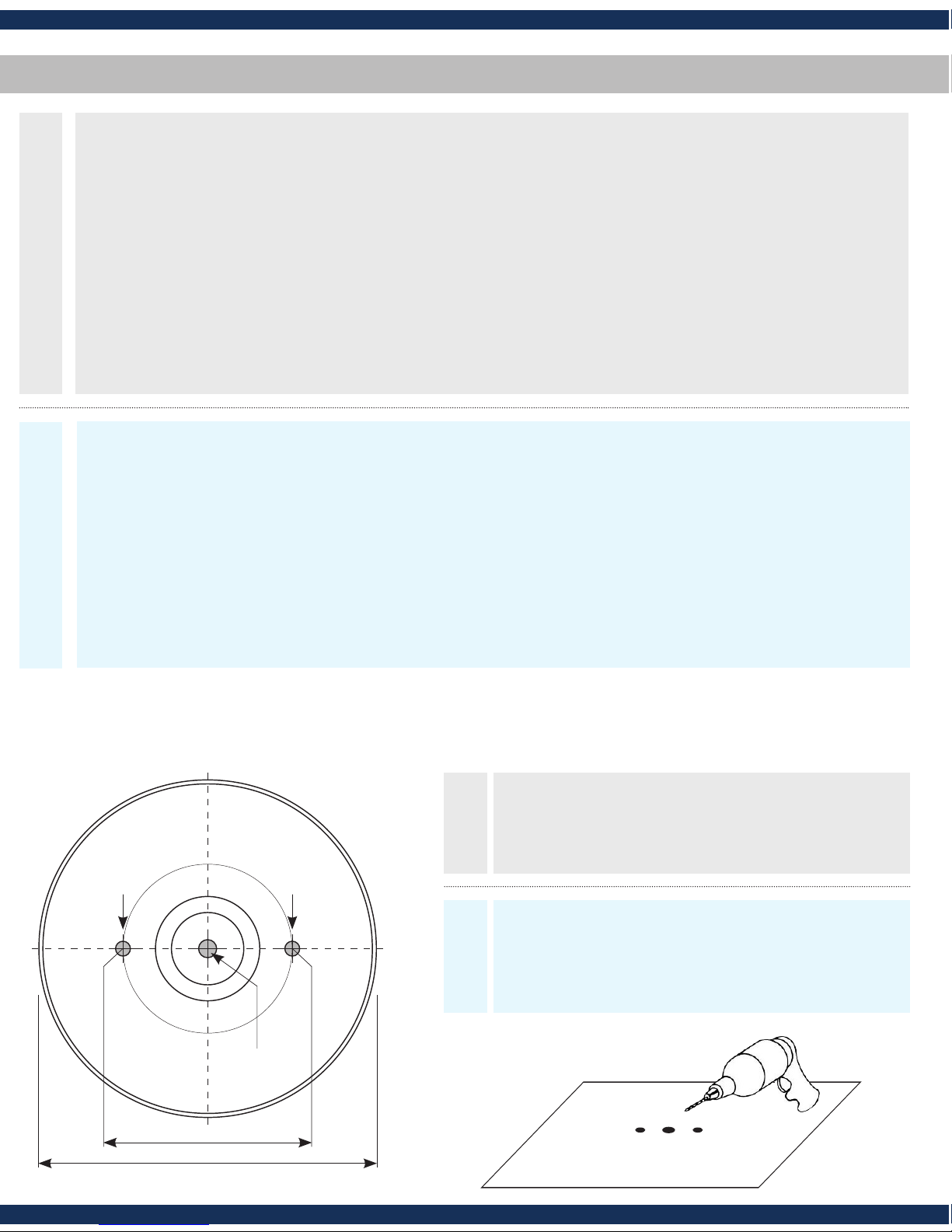
Antenna diameter 11 cm (4”)
Height 20 cm (8”)
Material UV resistant ASA
Scout S.r.l.
Via Toscanini 148
41019 Soliera (Modena)
Italy
tel. +39 059 566650
fax +39 059 565949
e-mail: scout@scoutantenne.com
web: www.scoutantenne.com
► Wave is guaranteed against defective parts or workmanship for 2 years from time of purchase.
This excludes any malfunction caused by improper use, accidental or malicious damage. This doesn’t
aect your statutory rights.
► If you do experience a problem with the product contact Scout Customer Services on +39 059
566650.
► All instructions and models are subject to change without prior notice.
► Please keep these instructions safe for future reference.
► Recycle packaging where facilities exist.
► Wave è garantita per 2 anni da difetti di fabbricazione in termini di materiale e lavorazione dal
momento dell’acquisto. La garanzia esclude ogni malfunzionamento derivante da uso improprio o
accidentale dell’oggetto.
► In caso di problema tecnico potete contattate il servizio clienti di Scout al numero +39 059 566650.
► Le speciche tecniche qui contenute possono variare a discrezione del produttore.
► Conservare le presenti istruzioni per consultazioni future.
► A ne vita non gettare questo apparecchio nella normale raccolta dei riuti, ma portalo presso dei
punti di raccolta autorizzati. In questo modo contribuirai a preservare l’ambiente.
ENG
ITA