TB-9021 Page 7 of 12 © 2015 DESCO INDUSTRIES, INC.
Employee Owned
SCS - 926 JR Industrial Drive, Sanford, NC 27332 • (919) 718-0000 • Website: StaticControl.com
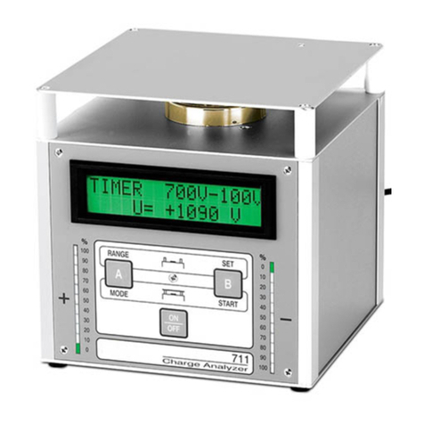
1. Press the “B” button (SET) to display SETUP B.
2. Press the “B” button to display the START 600-1100
voltage range menu.
3. Notice the blinking cursor under the thousandths
position of the four-digit voltage value located on the
second line of the display. Change the value of this
digit by pressing the “A” button momentarily.
4. Press the “B” button once to move the cursor to the
next digit and adjust the value (0-9) with the “A”
button.
5. Continue adjusting the value of the remaining digits
to the desired level. If you make a mistake continue to
press the “A” & “B” buttons consecutively to obtain the
desired value.
6. When the desired voltage value is obtained, continue
to press the “B” button until the display reads A<YES
& NO>B.
7. Press the “A” YES button to verify and store the start
voltage value. Pressing the “B” NO button repeats the
voltage value setting menu again.
8. The STOP 1-500 voltage range menu is now
displayed. Adjust the stop voltage using the “A” &
“B” buttons as described in the Start voltage
procedure above.
9. Press the “A” button YES to verify and store the stop
voltage value. Pressing the “B” NO button repeats the
voltage value setting menu again.
Note: If you should select a start or stop voltage
outside of the ranges listed above, the SCS 711
Charge Analyzer will not store that value. If the charge
plate does not reach the set stop voltage within 99.9
seconds the counter stops and the display ashes TIME
EXCEEDED. This message will appear in Positive,
Negative, and Auto decay modes.
Setting the Offset Time: When the start and stop
voltage procedure is completed the OFFSET menu will
be displayed. The offset time can be adjusted from 0
(Indenite time), 1 to 10 seconds (1-second steps), and
10 to 60 seconds (10-second steps). To change the
offset time perform the following steps:
1. Press “A” CHANGE button repeatedly to move
through time settings.
2. When the desired time is set, press the “B” OK button
to store. The start and stop voltage values with the
offset time value will then be displayed momentarily.
3. Next the display will indicate TIMER+ OFFSET OK.
If values are correct, press the “A” YES button. If
not, press the “B” NO button which will restart the start
voltage menu.
4. The display will then indicate CLEAR MEMORY if
changes were made. Press the “A” YES button to
store the revised settings. PARAMETER CHANGED
will momentarily appear. If no changes were made,
display will indicate PARAMETER NOT CHANGED.
Note: To measure offset balance for time periods longer
than 60 seconds, set offset time to zero seconds “0 s”.
This puts the Charge Analyzer CPM in a oating mode
for an indenite time period. The unit will not have an
active timer in this mode. Elapsed time must be recorded
by the operator using a stop watch or other time
recording device. Connection to the analog output using
a chart recorder e.g. allows for monitoring of the offset
voltage during long time periods. Pressing the “B” button
twice during the indenite offset time mode returns the
display to the DECAY TIME/START mode.
This completes the voltage range zeroing, start/stop
voltage, and offset time setup.
Static Decay Time and Balance Use
1. Remove the red sensor cover from the measurement
electrode.
2. Mount the plate electrode (b) to the 711 Charge
Analyzer. Be sure that the red sensor cover (e) is
removed from the sensor electrode. Display will
indicate DECAY TIME, voltage polarity (“Either” POS,
NEG, or AUTO) and PRESS START.
3. Press the “A” MODE button to select Positive,
Negative, or Auto (Positive & Negative) decay.
Note: In AUTO mode there will be an approximate 5
seconds delay between positive & negative decay tests.
4. The display will now indicate DECAY TIME: POS,
NEG, or AUTO on the rst line and PRESS START on
the second line.
5. Pressing the “A” YES button again after AUTO decay
is displayed will select the READ OFFSET CPM
menu. Pressing the “A” YES button will initiate the
system verication and the display will respond with
UPDATING.
Note: System verication (Zero point adjustment) is
only recommended before the rst measurement, when
parameters are rst set with the attachment of the plate
electrode. If the “B” button (NO) is pressed you will
return to the start of the DECAY TIME menu.
The SCS 711 Charge Analyzer is now ready to measure
static charge neutralization effectiveness and the offset
balance of ionizers.
Demonstration #6 Charge Plate Monitor and Static
Decay Time Measurements – Air Gun Ionizer
