manuals.online logo
Brands
  1. Home
  2. •
  3. Brands
  4. •
  5. SCS
  6. •
  7. Test Equipment
  8. •
  9. SCS 770734 User manual

SCS 770734 User manual

TB-9105 Page 1 of 4 © 2020 DESCO INDUSTRIES INC
Employee Owned
SCS - 926 JR Industrial Drive, Sanford, NC 27332
East: (919) 718-0000 | West: (909) 627-9634 • Website: StaticControl.com
724 Plus Monitor Verication Tester
Operation Instructions
Description
The SCS 770734 724 Plus Monitor Verification Tester
is used to perform periodic test limit verification of the
SCS 770724 724 Plus Workstation Monitor. Verification
may be accomplished without removing the monitor
from its workstation. The Verification Tester is National
Institute of Standards and Technology (NIST) traceable.
Frequency of verification is based on the critical
nature of the ESD susceptible items handled. SCS
recommends annual calibration of workstation monitors
and the 724 Plus Monitor Verification Tester. The SCS
724 Plus Monitor Verification Tester meets ANSI/ESD
S20.20 and Compliance Verification ESD TR53.
Packaging
1 724 Plus Monitor Verification Tester
1 Alligator Clip
1 10mm Stacking Snap
1 Ground Plug Adapter
1 Ground Extension Cord, 5'
1 9V Alkaline Battery
1 Certificate of Calibration
November 2020
Features and Components
Made in the
United States of America
Figure 1. SCS 770734 724 Plus Monitor Verication
Tester
USER GUIDE TB-9105
Figure 2. 724 Plus Monitor Verication Tester features
and components
B C
A
D
E
G
F
H
A. Ground Lead: Connect to equipment ground to
provide a ground reference for the 724 Plus Monitor
Verification Tester.
A. Mat Test Lead: Connect to the monitor's mat
terminal to verify its mat test circuit.
C. Operator Test Lead: Insert into the monitor's
operator jack to verify its operator test circuit.
TB-9105 Page 2 of 4 © 2020 DESCO INDUSTRIES INC
Employee Owned
SCS - 926 JR Industrial Drive, Sanford, NC 27332
East: (919) 718-0000 | West: (909) 627-9634 • Website: StaticControl.com
D. Rotary Switch: Selects the various pass and fail
load values needed to verify the monitor's operator test
circuit.
E. Body Voltage Pushbutton: Loads the selected
body voltage stimulus onto the Operator Test Lead
when pressed.
F. Body Voltage LED: Illuminates blue when the Body
Voltage Pushbutton is pressed and voltage stimulus is
applied onto the Operator Test Lead.
G. Mat Fail Pushbutton: Simulates a MAT FAIL
condition on the 724 Plus Workstation Monitor when
pressed.
H. Low Battery LED: Illuminates yellow when the
battery power for the body voltage test circuit is low and
needs to be replaced.
Operation
Verifying the Operator Resistance Circuit
1. Connect the 724 Plus Monitor Verification Tester's
green ground lead to equipment ground. This may
be done using the included Ground Plug Adapter or
alligator clip.
2. Insert the verification tester's black operator test
lead into the 724 Workstation Monitor's operator 1
jack.
3. Set the rotary switch to 1.5M LOW. The monitor's
operator 1 LED should blink yellow, and its audible
alarm should sound.
4. Set the rotary switch to 1.5M PASS. The monitor's
operator 1 LED should illuminate green, and its
audible alarm should not sound.
5. Set the rotary switch to either 10M PASS or 35M
PASS, whichever one is appropriate. The monitor's
operator 1 LED should illuminate green, and its
audible alarm should not sound.
6. Set the rotary switch to either 10M HIGH or 35M
HIGH, whichever one is appropriate. The monitor's
operator 1 LED should illuminate red, and its
audible alarm should sound.
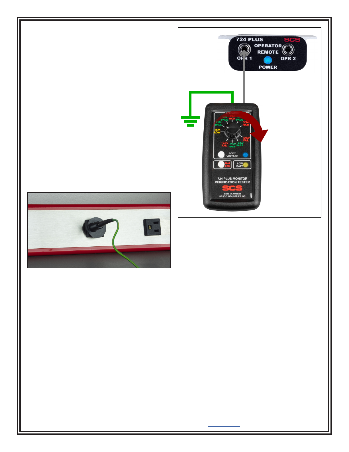
Figure 3. Using the Ground Plug Adapter to ground the
724 Plus Monitor Verication Tester
Figure 4. Connecting the 724 Plus Monitor Verication
Tester to the 724 Plus Workstation Monitor's operator 1
jack
Verifying the Operator Body Voltage Circuit
7. Set the rotary switch to +2.5V FAIL, and press the
Body Voltage Pushbutton. The monitor's operator 1
LED should blink red, and its audible alarm should
sound.
8. Set the rotary switch to +2.5V PASS, and press the
Body Voltage Pushbutton. The monitor's operator 1
LED should illuminate green, and its audible alarm
should not sound.
9. Set the rotary switch to -2.5V PASS, and press the
Body Voltage Pushbutton. The monitor's operator 1
LED should illuminate green, and its audible alarm
should not sound.
10. Set the rotary switch to -2.5V FAIL, and press the
Body Voltage Pushbutton. The monitor's operator 1
LED should blink red, and its audible alarm should
sound.
11. Disconnect the operator test lead from the monitor's
operator jack.
12. Connect the operator test lead to the monitor's
operator 2 jack. Repeat steps 1-11 to verify the
monitor's operator 2 resistance and body voltage
circuitry.
TB-9105 Page 3 of 4 © 2020 DESCO INDUSTRIES INC
Employee Owned
SCS - 926 JR Industrial Drive, Sanford, NC 27332
East: (919) 718-0000 | West: (909) 627-9634 • Website: StaticControl.com
Verifying the Mat Circuit
13. Connect the included stacking snap to the
verification tester's white mat test lead.
14. Disconnect the monitor's white mat monitor cord
from its worksurface mat and turn it over to expose
its 10mm snap.
15. Connect the verification tester's white mat test lead
to the mat monitor cord's 10mm snap. The monitor's
mat LED should illuminate green, and its audible
alarm should not sound.
16. Press the Mat Fail Pushbutton. The monitor's mat
LED should illuminate red, and its audible alarm
should sound.
Maintenance
Battery Replacement
Replace the battery once the Low Battery LED
illuminates yellow. Open the compartment located on
the back of the tester to replace the battery. The tester
uses one 9V alkaline battery. Ensure that the battery's
polarities are oriented correctly to avoid possible circuit
damage.
Figure 5. Connecting the 724 Plus Monitor Verication
Tester to the 724 Plus Workstation Monitor's mat monitor
cord
Figure 6. Removing the battery cover located on the
back of the 724 Plus Monitor Verication Tester
Calibration
Frequency of recalibration should be based on the
critical nature of those ESD sensitive items handled and
the risk of failure for the ESD protective equipment and
materials. In general, SCS recommends that calibration
be performed annually.
Use the information below to verify if the 724 Plus
Monitor Verication Tester operates within its
specications. The values may be verified using a digital
multimeter. Connect the multimeter's test leads across
the 724 Plus Monitor Verification Tester’s stereo plug. If
any value is out of specification, the Verification Tester
must be returned to the manufacturer for repair.
Resistance Values:
Setting Nominal
Resistance
% Tolerance of
Nominal Resistance
1.5M LOW 1.33 megohms ±2%
1.5M PASS 1.69 megohms ±2%
10M PASS 8.45 megohms ±2%
10M HIGH 11.5 megohms ±2%
35M PASS 29.4 megohms ±2%
35M HIGH 40.2 megohms ±2%
MAT FAIL 4.1 megohms ±2%
TB-9105 Page 4 of 4 © 2020 DESCO INDUSTRIES INC
Employee Owned
SCS - 926 JR Industrial Drive, Sanford, NC 27332
East: (919) 718-0000 | West: (909) 627-9634 • Website: StaticControl.com
Body Voltage Values:
Setting Nominal
Voltage
% Tolerance of
Nominal Voltage
-2.5V FAIL -1.38 V ±2%
-2.5V PASS -1.13 V ±2%
+2.5V PASS +1.13 V ±2%
+2.5V FAIL +1.38 V ±2%
Specifications
Operating Temperature 50 to 95°F (10 to 35°C)
Environmental
Requirements
Indoor use only at altitudes
less than 6500 ft. (2 km)
Maximum relative humidity
of 80% up to 85°F (30°C)
decreasing linearly to 50% @
85°F (30°C)
Dimensions 4.9" L x 2.8" W x 1.3" H
(124 mm x 71 mm x 33 mm)
Weight 0.2 lbs. (0.1 kg)
Country of Origin United States of America
Limited Warranty, Warranty Exclusions, Limit
of Liability and RMA Request Instructions
See the SCS Warranty -
StaticControl.com/Limited-Warranty.aspx

Other SCS Test Equipment manuals

SCS 724VK2 User manual

SCS

SCS 724VK2 User manual

SCS 770716 Installation guide

SCS

SCS 770716 Installation guide

SCS 770758 Installation and operating instructions

SCS

SCS 770758 Installation and operating instructions

SCS 746 User manual

SCS

SCS 746 User manual

SCS TB-9029 User manual

SCS

SCS TB-9029 User manual

SCS 740 User manual

SCS

SCS 740 User manual

SCS 770065 User manual

SCS

SCS 770065 User manual

SCS 770030 User manual

SCS

SCS 770030 User manual

SCS TB-9031 User manual

SCS

SCS TB-9031 User manual

SCS 770065 User manual

SCS

SCS 770065 User manual

SCS WSMONITOR2 Plus User manual

SCS

SCS WSMONITOR2 Plus User manual

SCS TMTOOL Installation and operating instructions

SCS

SCS TMTOOL Installation and operating instructions

Popular Test Equipment manuals by other brands

X-Rite i1Display Setup guide

X-Rite

X-Rite i1Display Setup guide

Tektronix TDS1001B Security instructions

Tektronix

Tektronix TDS1001B Security instructions

REED ST-156 instruction manual

REED

REED ST-156 instruction manual

Bibby Sterilin TECHNE Tecal 425S Operator's manual

Bibby Sterilin

Bibby Sterilin TECHNE Tecal 425S Operator's manual

Sealey AUTO SERVICE VSE206 instructions

Sealey

Sealey AUTO SERVICE VSE206 instructions

BDI S100 STINGER quick start guide

BDI

BDI S100 STINGER quick start guide

BEVS 1606 user manual

BEVS

BEVS 1606 user manual

Servonaut DiCa manual

Servonaut

Servonaut DiCa manual

ACS A1410 PULSAR Operation manual

ACS

ACS A1410 PULSAR Operation manual

Klein Tools ET600 instruction manual

Klein Tools

Klein Tools ET600 instruction manual

JDS Uniphase T-BERD manual

JDS Uniphase

JDS Uniphase T-BERD manual

Lafayette 01163 user manual

Lafayette

Lafayette 01163 user manual

Wingmate Pro user manual

Wingmate

Wingmate Pro user manual

GenRad GR228X introduction

GenRad

GenRad GR228X introduction

Humboldt Deluxe Series product manual

Humboldt

Humboldt Deluxe Series product manual

Silverado BST-380 user guide

Silverado

Silverado BST-380 user guide

Bante Instruments PHscan20S/F instruction manual

Bante Instruments

Bante Instruments PHscan20S/F instruction manual

B&K 230 operating manual

B&K

B&K 230 operating manual

manuals.online logo
manuals.online logoBrands
  • About & Mission
  • Contact us
  • Privacy Policy
  • Terms and Conditions

Copyright 2025 Manuals.Online. All Rights Reserved.