B&K 230 User manual

E
&.::E-t:
INSTRUMENTS
.
INC
.
May
1972
OPERATING MANUAL
for
MODEL
230
CALIBRATION
CONTROL
OSCILLATOR

SECTION
I
SECTION
II
SECTION
III
SECTION
IV
TABLE
OF
CONTENTS
General
Description
1.1
1.2
Description
.
Specifications
Installation
Theory
of
Operation
3.1
3.2
Oscillator
Circuit
Impedance
Head
Circuits
Operation
4.1
Calibration
of
.B &K
Model 4930
Artificial
Mastoid
4.1.1
General
4.1.2
Equipment
Hook-Up
4.1.
3
Calibration
Set-Up
Procedure
4.1.4
Setting
the
Mass
Compensation
4.1.5
Calibrating
the
Model 4930
Mastoid
i
1
1
1-2
3
5
5
6
7
7
7
7-8
8-11
11
11-13

Figure
1.
Figure
2.
Figure
3.
Figure
4.
Drawing
A-1604
Drawing
A-d605
Drawing
C-1603
Drawing
B-1602
Drawing
A-1601
ILLUSTRATIONS
Picture
of
Model 230
Calibration
Control
Oscillator
Simplified
Diagram
-Model 230
Instrument
Interconnections
-
4930
Calibration
Periodic
Calibration
of
Model
4930
Artificial
Mastoid
(B
& K Form
#2-358)
Oscillator
Block
Diagram
Model 230
Preamplifier
Block
Diagram
Model 230
Schematic,
Oscillator
for
Model 230
Schematic,
Preamplifier
for
Model 230
Schematic,
Power
Supply
for
Model 230
ii
4
5
10
14
SECTION
I
GENERAL
DESCRIPTION
1.1
Description
The B & K Model 230
Calibration
Control
Oscillator
and
the
B & K
Model
4931
Artificial
Mastoid
Calibrator
are
used
together
to
calibrate
the
frequency
response
and
force
sensitivity
of
the
B & K Model
4930
Artificial
Mastoid.
The Model 230
Calibration
Control
Oscillator
has
eleven
pushbutton-selected
variable
level
test
tones
in
the
range
from
125
to
8000
Hz,
in
accordance
with
the
ANSI
1)
and
IEC2)
audiometer
test
standards.
The
calibration
control
oscillator
also
contains
the
signal
conditioners
for
transducer
signals
from
the
Artificial
Mastoid
and
the
force
and
acceleration
outputs
of
the
Impedance
Head
Model
8000.
A
mass
compensation
circuit
is
included
to
cancel
out
the
residual
mass
below
the
force
sensing
element.
Mass
compensation
at
1000
Hz
reduces
the
effect
of
residual
mass
to
below
0.2
%
of
the
true
force
signal
level
at
all
test
tone
frequencies.
An
external
rms
volt-
meter
is
used
with
the
Model 230
to
read
both
the
force
applied
and
the
mastoid
output.
1.2
Specifications
Oscillator
Output
Frequencies:
Frequency
Accuracy:
Output
Level
(Filter
Out)
:
Output
Impedance:
Distortion:
Filter
Characteristics:
125,
250,
500,
750,
2000,
3000,
4000,
+~
1000,
6000,
1.3
V rms
into
6
Ohm
load
10
Ohms
2%
at
0.1
V rms
1500,
8000
Hz.
High
pass,
0.5
dB
at
3 kHz
and
-10
dB
at
125
Hz.
1)
-
ANSI
Stand
ar
d
S3.13-1972:
An
Artificial
Head-Bone
for
the
calibration
of
Audiometer
Bone
Vibrators.
2) -IEC
Draft
Document
29C
(Cent
r
al
Office)9.

1.2
Specifications
(Cont'd)
Signal
Circuits
Inputs:
Input
Impedance:
Frequency
Response:
Noise:
Maximum
Input:
Output
Impedance:
Gain:
Mastoid
-
Force
Acceleration
Power:
Size:
.
Weight:
Rack-Mounting
Adapters
Single
Unit:
Dual
Units
Accessories:
-2-
3
(Acceieration
and
Force
from
Model
8000
Impedance
Transducer
and
Force
from
4930
Mastoid)
5 M-ohms
30 -
10,000
Hz
+0.5
dB
100
~V
with
respect
to
the
input
with
1000
pF
input
capacitor
3 V
peak
200
Ohms
o
dB
o
dB
o
to
-40
dB
prior
to
summing
115/230
V;
50-400
Hz;
15
watts
8
Tf
wide
x
3%-Tf
high
X
l3
Tf
deep
8
lbs
KS
1-1001
KS
1-2001
1 Power
Cord
1
3-ft.
Signal
Cord
BNC
to
B&K
1
Signal
Cord
Microdot

2.1
Inspection
SECTION
II
INSTALLATION
Remove
the
Model 230
Calibration
Control
Oscillator
from
its
packing
and
inspect
the
instrument
for
damage.
(Make
certain
that
the
power
and
signal
cords
are
-
not
discarded
with
the
carton.)
2.2
Installation
The B & K Model 230
Calibration
Control
Oscillator
may
be
operated
as
a
bench-top
instrument.
A
bail
on
the
lower
cover
tilts
the
instrument
fo
r
convenient
use.
For
rack-mounting,
adaptor
KS
1-1001
attaches
to
the
instrument.
Mounting
instructions
are
included
with
the
rack
adaptor.
Before
applying
power,
check
the
line
voltage
selector
at
the
rear
of
the
instrument
and
make
sure
the
switch
is
in
the
correct
position
(115
or
230).
See
Figure
1.
(Picture
of
the
Model 230
showing
front
controls.)
-3-

.
~,
.::t2~
~
~·
~
-.:
._
~;'Io-
A
(5)
F
(Q)
~
M
(6)
"
Osc:
®
;1 Output
~
~
.."ll:
230 CALIBRATION
CONTROL
OSCILLATOR
"'-
Mcidol
'd o.c;c ll!vel
Il'I
-
Moifr;,id
fiI,
..
D
Out
-
Oth
~
,.
rry
O
·
O l
.tput
Qu
-
otUt
•
Adjust Moss Compensation
[[[[]]TI]]
n
125
250 500
75,0
IK I.SK
21.
3K
;fK
6K
8K
Oscillator Frequen
cy
@
Po·
....
er
o
,
t":::;;
~
l
~I
.'
:
:
C
~
~
-"
j;
"
~
.,
~
~
"
.
;
;
.
:
./
'/
O u
tput
to
Mef
e r
.
".
t
'.
:..:..,-!
.
';:
.':':
;" -~
_
-":':"'::'
_'
_ _
-.-
.' • •
.o...-:
..
_
;",,_-
.__ , t.
...
~
..
~
~
.\'
1,
1
""""
.
:;
,
~
:~
I \ '
~1
~
~;
",
~
,
i!
1
~~---
\
~'IP~
·
~~,.j;..<o
..
-
·
~"':t~
L
~
.
,
~,-<,
~~
_,u.
.
~
___
.---_~-:.;
..
....,~
.•
""_,
..;t1
'J'
~~
_
~
.
~
:::-:::!
-;
7-=.
-~
~
~--"~~~"'lI
'
d
,!.
"
Y':1I
'-
~
.
..
.
--
...
~
-
-:::::~
.
~:
/
~
Fi~
Ul:'El.
h
I
+
I

3.1
Oscillator
Circuit
SECTION
III
THEORY
OF
OPERATION
-5-
A
simplified
block
diagram
is
shown
in
Figure
2.
The
frequency
selector
pushbuttons
S.4
select
the
frequency
of
an
RC
oscillator.
'
Eleven
frequencies
at
125,
250,
500,
750,
1000, 1500,
2000,
3000,
4000,
6000
and
8000
Hz
are
provided.
The
oscillator
output
connects
either
directly
to
the
output
amplifier
or
through
a
high-
To
Rcm
lout
F
-
--,
• I
I
I
5
Ing
le
I
(-
l
ass
.
COIll
(l.
I
I
I
I
I
I
I
I
I
I
I
I
I
I
I
I
_J
Frequency
,
Sclector
IIR1
0
Nini
-
Sh(1kcr
5.5
230
C.C.O.
5.
11
(~lot1el
3000 Impcdnnce H
ead
)
~lodcl
'
II')30
Artificial
Nastoid
Figure
2.
Simplificd
Dingram -Hodel 230
Calibration
Control
Osci
ll
at
or
pass
filter
F.l.
Pushbutton
switch
S.5
inserts
the
high-pass
filter
into
the
circuit.
The
output
voltage
characteristic
of
this
filter
approx-
imates
the
inverse
of
the
mechanical
impedance
character-
istic
of
the
Model 4930
Mastoid.
Hence,
the
oscillator
output
to
the
Mini-
shaker
matches
the
impedance
of
the
driven
tlload
tl
(the
mastoid).
With
the
filter
switched
in,
adjustment
of
the
oscillator
level
control
is
minimal.

-6-
3.2
Impedance
Head
Circuits
The B & K Model 8000
Impedance
Head
has
a
force
output
and
an
accelera-
tion
output.
Both
transducers
are
piezoelectric
and
are
connected
to
high
input
impedance
amplifiers
A.2
and
A.3.
The
Minishaker
Model
4810
applies
force
to
the
Artificial
Mastoid
through
the
Impedance
Head
contact
surface,
a
beryllium
disc
of
1.75
cm
2,
as
specified
by
IEC-29C.
The
force
level
applied
is
read
from
the
force
gage
output
of
the
Impedance
Head.
For
applications
in
the
United
States,
the
Model 4930
Mastoid
is
calibrated
in
force
(mV/Newton). The
disc
which
bears
on
the
Model 4930
Mastoid
has
a
mass
of
about
1.1
grams.
This
mass
loads
the
lower
side
of
the
force
transducer
and
creates
an
acceleration
signal
when
in
motion.
This
signal
adds
to
the
force
signal
and
results
in
an
error.
To
eliminate
this
undesired
signal,
there
is
an
accelerometer
built
into
the
Impedance
Head.
The
output
of
this
accelerometer
is
in
opposite
phase
to
the
force
output.
By
mixing
a
portion
of
the
accel-
erometer
output
with
the
force
gage
output,
the
effects
of
the
residual
mass
are
cancelled.
To
effect
complete
cancellation,
the
Impedance
Head
and
Minishaker
are
lifted
clear
of
contact
with
the
top
of
the
Artificial
Mastoid
and
a
1000
Hz
tone
is
applied
to
the
Impedance
Head.
Since
there
is
no
load
on
the
force
gage,
the
only
signal
generated
in
the
force
gage
is
the
undesired
acceleration
signal.
The
amount
of
the
out-of-phase
acceleration
signal
added
is
set
with
the
mass
compensation
screwdriver
adjustment
so
that
a minimum
voltage
reading
(max.
cancellation)
is
obtained
at
the
output
jack
(Output
Switch
S.3
in
"FORCE"
position)
.
The
mass
compensation
screwdriver
adjustment
is
on
the
front
panel.
Mass
compensation
performe
d
at
100
0
Hz
serves
all
other
test
tones
as
well.
Error
will
be
less
than
0.2
%.
Switch
S.3
selects
the
output
of
the
mass
compensated
force
signal
or
the
Mastoid
output.
The t wo
signal
levels
can
be
measured
on
any
external
voltmeter
our
sound
level
meter.
-7-
SECTION
IV
OPERATION
4.1
Calibration
of
B & K Model 4930
Artiticial
Mastoid
4.1.1
General
The B & K Model 4930
Artificial
Mastoid
is
a
force
measuring
load
cell
with
an
elastic
sensing
face.
The
mechanical
impedance
is
similar
to
the
human
mastoid.
The Model
4930
measures
the
mechanical
output
of
the
bone
conduction
transducers
when
driven
from
audiometers.
Mastoid
calibration
establishes
the
'
transfer
function
of
the
Model
4930;
i.
e.
what
electrical
output
is
obtained
for
a known
input
force
at
each
test
frequency.
Because
of
the
differences
between
U.S.
and
European
equipment
and
standards
for
bone
conduction
calibration,
this
manual
will
show a
different
complement
of
equipment
and
some
procedure
differences
from
those
in
the
Bruel
&
Kjaer
manual
for
the
Model 4930
Mastoid.
For
U.S.
applications,
this
.
manual
should
take
precedence
using
the
Model 4930
manual
for
supplementary
data.
4.1.2
Eguipment
Hook-Up
The
instruments
to
perform
a Model 4930
Artificial
Mastoid
calibra
tion
are:
- 1 230
Calibration
Control
Oscillator
with
microcable
set
and
output
cable
4810
Minishaker
8000
Impedance
Head
Calibration
Loading
Arm
Static
Adjuster
550 gram Mass
Bubble
Balance

-8-
4.1.2
Equipment
Hook-Up (ContTd)
The
measuring
amplifier
or
voltmeter
which
is
normally
used
with
the
Model 4930
Mastoid
can
be
used
for
the
calibration.
Suitable
types
include:
4.1.3
2203 Sound
Level
Meter
2204
Sound
Level
Meter
2209
Sound
Level
Meter
2603
Microphone
Amplifier
2604
Microphone
Amplifier
2606
Microphone
Amplifier
2607
Microph0ne
Amplifier
.c-2608
Microphone
Amplifier
2107
Analyzer
2112
Analyzer
2113
Analyzer.
Calibration
Set-Up
Procedure
A. Remove
the
bone
conductor
loading
arm
from
the
Model
4930.
Install
the
calibration
loading
arm
for
supporting
and
positioning
the
Minishaker,
as
illustrated
below.
Calibration
Loading
Arm
~
Minishaker
Install
the
compression
type
static
load
adjuster
on
the
base
plate
containing
the
Mastoid.
Mount
the
Impedance
Head
to
the
Minishaker
and
position
and
secure
the
combination
in
the

4.1.3
-9-
Calibration
Set-Up
Procedure
(Cont'd)
loading
arm.
As
with
the
bone
vibrator,
it
is
important
to
have
the
correct
static
load
applieo
to
the
Mastoid
and
to
have
proper
positioning.
The
Impedance
Head
center
should
rest
on
the
highest
point
of
the
domed
top
of
the
Mastoid.
To
effect
this
centering,
rotate
the
loading
arm
horizontally
in
its
post
and,
by
loosening
the
knurled
nut
securing
the
mounting
post
to
the
platform,
shift
the
loading
arm
assembly
in
the
platform
slot
for
vertical
centering.
Retighten
the
knurled
nut.
The
Impedance
Head
should
be
as
vertical
as
possible
and
the
loading
arm
as
level
as
possible.
The
small
bubble
balance
included
with
the
Mastoid
may
be
placed
on
top
of
the
loading
arm
for
ease
of
leveling.
The
brass
static
loading
mass
should
not
be
installed
at
this
time.
Counterbalance
the
combined
weight
of
the
Minishaker
and
loading
arm
with
the
compression-type
static
load
adjuster.
To
perform
this
adjustment,
place
a
thin
piece
of
paper
(chart-
paper)
between
the
domed
top
of
the
Hastoid
and
the
contact
surface
of
the
Impedance
Head
and
rotate
the
static
load
adjuster
counter-~lockwise
to
pick
up
the
loading
arm
weight.
Correct
adjustment
is
obtained
when
there
is
a
light
drag
on
the
piece
of
paper
as
it
is
pulled
between
the
Impedance
Head
and
Mastoid.
If
leveling
now
needs
re-adjustment~
the
counter-balancing
should
be
touched-up
afterwards.
See
that
a
10-32
mounting
stud
is
screwed
into
the
back
of
the
Minishaker
to
provide
centering
for
the
loading
mass.
But
do
not
install
the
loading
mass
yet.
B.
Connect
the
microdot
cable
harnes~
as
shown
in
Figure
3.
Each
end
of
the
cables
is
coded
to
assure
ease
of
correct
connection.
The
cable
for
connection
between
the
Model 230
and
the
readout
instrument
has
a
BNC
connector
for
the
230
on
one
end
and
a
Bruel
&
Kjaer
connector
on
the
other
end
for
the
instruments
listed
under
4.1.2.
If
any
of
the
sound
level

-10-
4.1.3-B
Calibration
Set-Up
Procedure
(ContTd)
I.
-
_~
,,,
._
"-
..
l!2
•.
~
Jl
..
M
~
r-------t----t-----ir---;::;;::-;;t-~
tr[[t'[[rC[CI
(
~H---,
Ou
tpu
t
II
'
no
toO
"tO
o
.,
;,
;...::",
,
:.....:.
U
50<
,.
to
230
Cal.Control
Oscillator
'I'
Meter
4930 '
Arti
f
icial
Mastoid
.1
Figure
3.
Measuring
Amplifier
OR
I
I
I
L-_
Instrument
Interconnections;
4930
Calibration.
Sound
g
Level
~
M
eter
meters
or
the
Model
159
Audiometer
Calibrator
are
used
as
the
readout
instrument,
replace
its
microphone
with
the
B & K
Socket
Adapter
JJ-2612
for
the
models
2203
and
159,
and
JJ-2614
for
the
models
2204
and
2209,
to
accept
the
B & K
cable
connector.

-11-
4.1.3
Calibration
Set-Up
Procedure
(ContTd)
4.1.4
4.1.5
C.
Turn
on
the
Model 230
Calibration
Control
Oscillator
and
the
measuring
amplifier
and
allow
to
stabilize
for
15
minutes.
Set
Filter
Switch
S.5
TTIN-MASTOIDfT.
Setting
the
Mass
Compensation
A.
Raise
the
loading
arm
with
Minishaker
and
Impedance
Head
clear
of
the
Mastoid
and
block
it
in
this
up
position
by
placing
an
object
such
as
an
eraser
as
a
spacer
between
the
loading
arm
and
the
plungsr
of
the
static
load
adjuster.
B.
On
the
Model 230
select
the
1000
Hz
test
frequency,
set
TTOSC.
LEVELTT
mid-position,
and
set
the
output
switch
S.3
in
TTOUT-FORCE
TT
position.
C.
Adjlist
the
screwdriver
TTMASS
COMPENSATION
TT
control
on
the
Model 230
(above
theTTIOOO
HzTT
button)
for
minimum
deflection
of
the
readout
instrument.
This
completes
the
mass
compensation
operation.
D.
Remove
the
block
holding
the
Impedance
Head
up
and
lower
onto
the
Mastoid.
Now,
place
the
550
gram
static
loading
mass
over
the
mounting
stud.
(The
unthreaded
end
of
the
hole
in
center
w
ill
f
it
over
the
mounting
stud.)
The
Mastoid
arrangement
is
now
ready
for
calibration.
Calibrating
the
M
odel
4930 M
astoid
The
frequency
response
of
the
force
gage
in
the
Impedance
Head
is
flat
well
beyond
the
operating
range
of
the
Mastoid
• .
This
force
gage,
therefore,
serves
.
as
the
calibration
reference.
By
holding
the
force
gage
readings
constant
"
for
eaph
test
tone,
'.
4.1.5
-12-
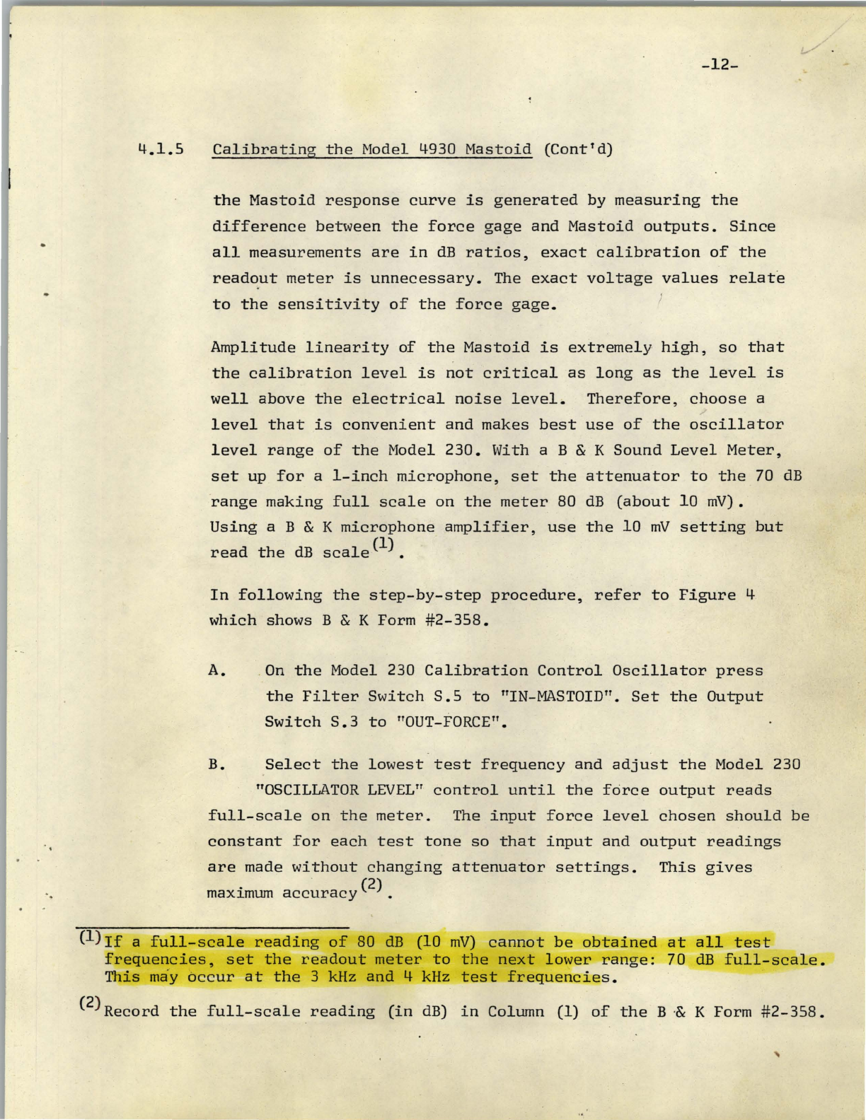
Calibrating
the
Model 4930
Mastoid
(Contfd)
the
Mastoid
response
curve
is
generated
by
measuring
the
difference
between
the
force
gage
and
Mastoid
outputs.
Since
all
measurements
are
in
dB
ratios,
exact
calibration
of
the
readout
meter
is
unnecessary.
The
exact
voltage
values
relate
to
the
sensitivity
of
the
force
gage.
Amplitude
linearity
of
the
Mastoid
is
extremely
high,
so
that
the
calibration
level
is
not
critical
as
long
as
the
level
is
well
above
the
electrical
noise
level.
Therefore,
choose
a
level
that
is
convenient
and
makes
best
use
of
the
oscillator
level
range
of
the
Model
230.
With a B & K
Sound
Level
Meter,
set
up
for
a
I-inch
microphone,
set
the
attenuator
to
the
70
dB
range
making
full
scale
on
the
meter
80
dB
(about
10
mV).
Using
a B & K
microphone
amplifier,
use
the
10
mV
setting
but
read
the
dB
scale
(1) •
In
following
the
step-by-step
procedure,
refer
to
Figure
4
which
shows B & K Form
#2-358.
A. .
On
the
Model 230
Calibration
Control
Oscillator
press
the
Filter
Switch
S.5
to
"IN-MASTOIDTT.
Set
the
Output
Swi
tch
S.
3
to
"OUT-FORCE".
B.
Select
the
lowest
test
frequency
and
adjust
the
Model 230
"OSCILLATOR
LEVEU'
control
until
the
force
output
reads
full-scale
on
the
meter.
The
input
force
level
chosen
should
be
constant
for
each
test
tone
so
that
input
and
output
readings
are
made
without
changing
attenuator
settings.
This
gives
maximum
accuracy
(2) •
(l
)
If
a
full-scale
reading
of
80
dB
(10
mV)
cannot
be
obtained
at
all
test
frequencies,
set
the
readout
meter
to
the
next
lower
range:
70
dB
full-scale.
This
ma
·y
occur
at
the
3 kHz
and
4 kHz
test
frequencies.
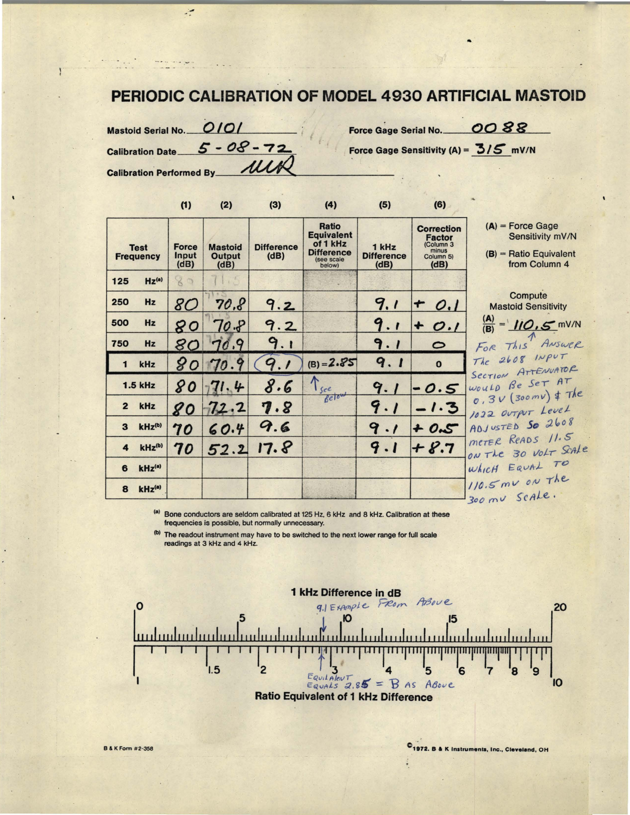
(2)
Record
the
full-scale
reading
(in
dB)
in
Column (1)
of
the
B
.&
K Form
#2-358.
-13-
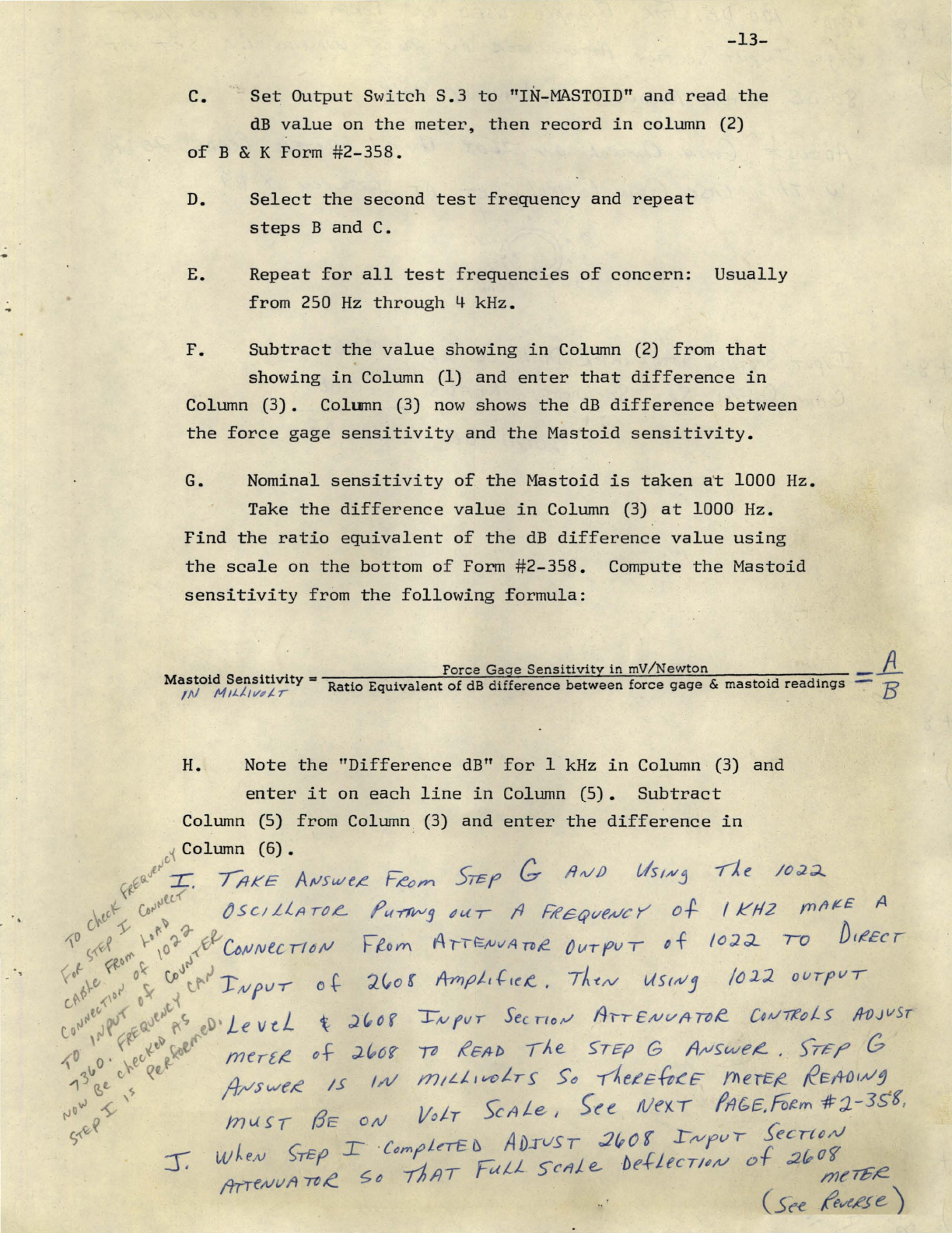
C.
Set
Output
Switch
S.3
to
"IN-MASTOID"
and
read
the
dB
value
on
the
meter,
then
record
in
column
(2)
of
B & K Form #
2-358.
D.
Select
the
second
test
frequency
and
repeat
steps
Band
C.
E.
Repeat
for
all
test
frequencies
of
concern:
Usually
from
250
Hz
through
4
kHz.
F.
Subtract
the
value
showing
in
Column (2)
from
that
showing
in
Column (1)
and
enter
that
difference
in
Column
(3).
Column (3)
now
shows
the
dB
difference
between
the
force
gage
sensitivity
and
the
Mastoid
sensitivity.
G.
Nominal
sensitivity
of
the
Mastoid
is
taken
a~
1000
Hz.
Take
the
difference
value
in
Column (3)
at
1000
Hz.
Find
the
ratio
equivalent
of
the
dB
difference
value
using
the
scale
on
the
bottom
of
Form
#2-358.
Compute
the
Mastoid
sensitivity
from
the
following
formula:
Force
Gage
Sensitivity
in
mV/Newton
_.A
Mastoid
Sensitivity
=
Ratio
Equivalent
of
dB
difference
between
force
gage
&
mastoid
r.
ead1ngs
-
7::?
/N
MIJ.tl
wl-
r V
H.
Note
the
"Difference
dB"
for
1 kHz
in
Column (3)
and
enter
it
on
each
line
in
Column
(5).
Subtract
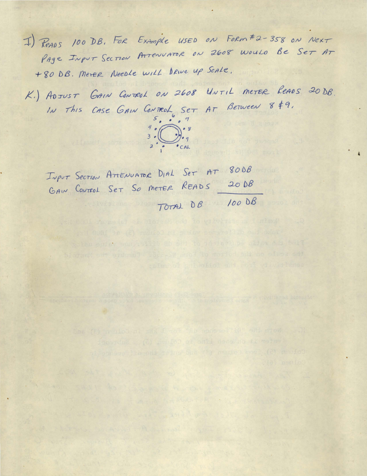
::r.)
reA{)S
/tJO
PB
I
F;,e
Ex.4mjJle.
lIS£D
tJ/V
FCl,e;n
#;2-
3s-g
()N
/VeK-{
fll-Je
J"vrv-r
S;ecn",v {h--reN
l/fr'T7J/!.
()tt./
;2«:;olT
woufA)
te...
S-er
/1r
+
<60
/)
13.
(nen:F!-
NeeDLe
w/LL
.D
til/€-
uf1
Sc~Le
I
,1(,)
,40
'ILlS
T
T',vfvr
)ecT"tPrJ
Anc,.,vuAilI,e
b,A-L
Se,
frT
GfI,;J
CotJTtoL
S'eT
So
(heTEF?-
l!..eA
D S
/00
DB
..
PERIODIC CALIBRATION OF MODEL
4930
ARTIFICIAL MASTOID
Mastoid
Serial No. 0
to
I Force
Gage
Serial No.
__
....!oo~o~~8~RL-_
Calibration
Date._~S-~----:()=---=e~------.:7~2...=.-
Force
Gage
Sensitivity
(A) =
:!>
I
S"
mV
IN
Calibration
Performed
By_---"AUA.'--='---=~__.30._
______
_
(1)
(2)
(3)
(4)
Ratio
Equivalent
Test
Force
Mastoid
Difference
of1
kHz
(5)
1 kHz
(6)
Correction
Factor
(Column 3
minus
(A) = Force Gage
Sensitivity mV/N
Frequency
Input
(dB)
Output
(dB) Difference
(see scale
Difference
Column 5)
(B)
= Ratio Equivalent
from Column 4
(dB) below) (dB) (dB)
125
Hz")
!)
"1
250
Hz
80
7(),R
'i.
2-
CJ.
, of-
0.
I Compute
Mastoid Sensitivity
500
Hz
(;0
'70.P
~.2.
CJ
• I +
0.1
750
Hz
80
"i
t.9
C}.
t
,.
, 0
(A) \ I 0 .
(
B)
= L,.s=mV/N
.
1"
Fote
TJ,
IS
AtUswel!.-
1 kHz
eO
70.9
(
q.,
""
(B)=2.n
q.
I 0
1.5
kHz
90
/
11.
Ir
8.'
t
5~<!C
Cf.
I
-O.S
IA~
:t(,tJ
1
IJJ!'v,
SU'r/o!o/
Arr£;t/I//Ht;~
Wol.(
Lf)
fie
SeT
AT
0,
3\1
(300J1'1V)
st
-rAe.
2
3
4
6
8
kHz
Ro
,-,
7,2..2-
'1.a
8
e1O
·
9·
I
-I.~
kHzlb)
70
, 0.'1
q.~
Cf
•,
~
O.s-
kHz'b)
70
52.%.
'7o~
<1
.,
+1?7
kHz")
kHz")
(.) Bone conductors are seldom calibrated at
125
Hz,
6 kHz and 8 kHz. Calibration at Itlese
frequencies
is
possible, but nonnally unnecessary.
(b) The readout instrument may have to
be
switched to the next lower range for full scale
readings at 3 kHz and 4 kHz.
1 kHz Difference in
dB
)4:1;1..
OVTfIIT
Lel/et
!toJ
V5Tcb 50
;J.
foo
8
m(TEI!.
ReADS /
/.
S" .
0'"
-rl-e
30
Vot,
YAle
v..J!.,cH
£
fRyltJ.-
TO
Ij().S'm
v o/V
-rAe,
300
(TIV
~cllLe,
o
'1./
'E
f.fIf7Ipi
t:.-
F,e4""
fb:1.w
e.,
20
I 5
.
~
~
~
I
11111111111111111111111111111111111111111111111111111111111111111111111111111111111111
I1111111111
," ,,,
I'
,r
'"
,,I0
",""1"
11
1""1""1""1"'1"
"1'''1'
1'1'
1'1
2 3 4
56789
EClv,lll/rllll
~
EQ.v!'tLs
<2,
g
:J)
:::
13
II
~
AtJtw
c.
10
Ratio Equivalent
of
1 kHz Difference
B & K Form #2·358
C1~72
.
B • K
Inllrumonll
, Inc
.•
Clne'.nd
,
OH
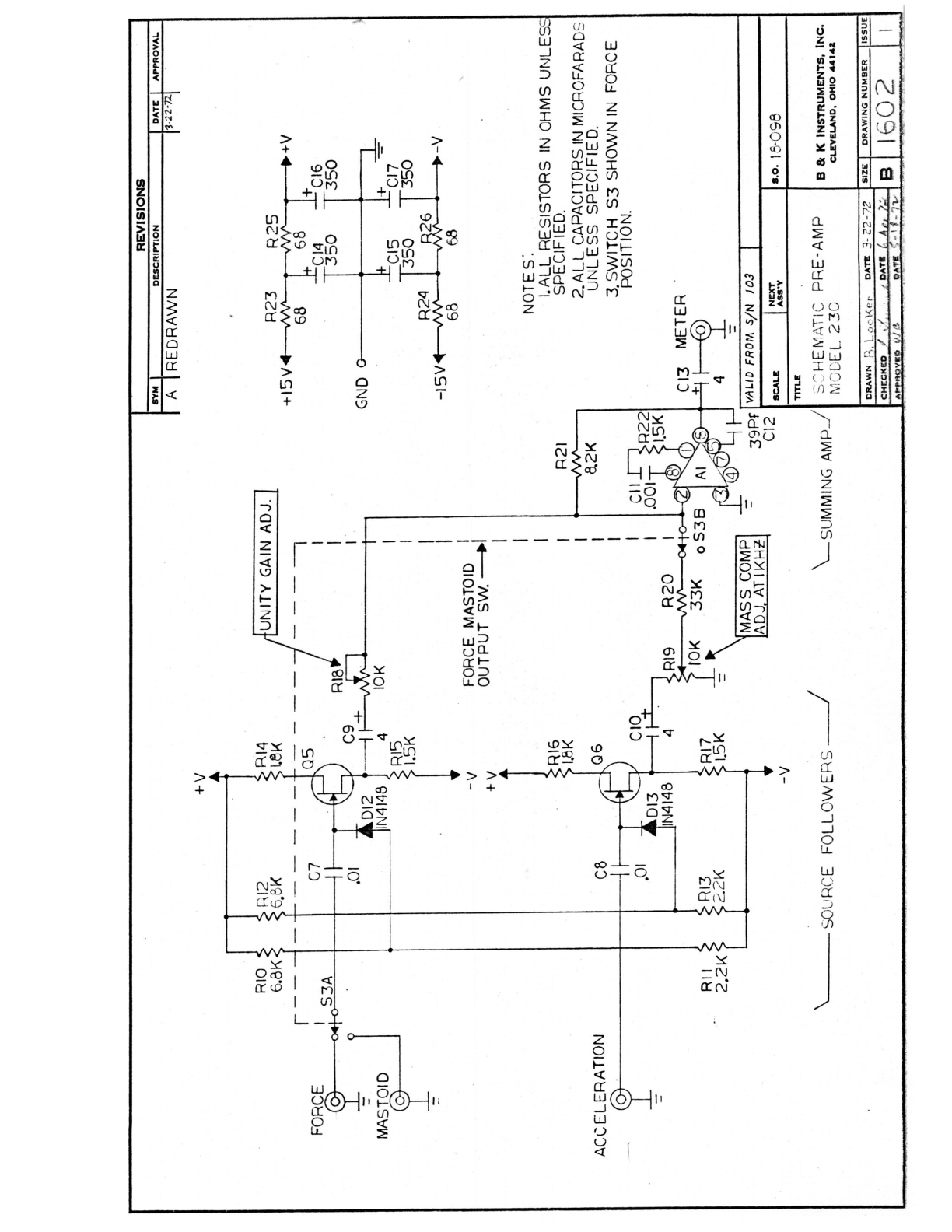
FORCE
MASi'D
J
ACCELERATION
RIO
5.8K
r--
I
S3A
RII
2.2K
RI2
6.BK
RI3
2.2K
+v
-v
+v
-v
\ -0 /
~--
S URCE
FO
LL
O
WE
RS
---.I
10K
UNITY GAIN ADJ.
---,
I
I
I '
I
I
I
I
FORCE
MASTOID
II
OUTPUT
Sw.
~
R20
33K
I
I
I
MASS
COMP
ADJ.
AT
IKH~
R21
8.2K
REVISIONS
BY
...
DESCRIP'TION
AP'I"ROVAL
A I REDRAWN
R23
+15V
+V
58
I~~t
GND
0
~
=b-
CI7
/'
• V
-15V
68
NOTES'.
I.ALL
RE
SISTORS
IN
OHMS
UNLE
SPECIFIED.
2.ALL
CAPACITORS
IN
MICROFARAD
S
UNLESS
SPECIFIED.
3. S
WITCH
S3
SHOWN
IN
FORCE
POSITION.
(13
METER
+~~
3~t~f
1"
'-'-
...
-
...
-/,"
.
--
SCALI:
•.
0·1
8-0 98
TITLE
"-S
UMMING
AM
P-.l
1
S:
HEM
ATIC
PR
E-AMP
MOG
EL
23
0 B & K INSTRUMENTS,
INC.
CLEVELAND.
OHIO
~1.2
SIZE'
DRAWING
NUMSER
I
CHECK
eD "
.•
:' •
..
'. '
DAn
~
41i
'
!f
l e I 16
02

REVISIONS
SYM I
DESCRIPTION
I
DATE
I
APPROVAL
I
I
r
-L
_
01
11
~
J2:
P2
2ooo~;T
J-
_
;;~
;>
r>1
-'-
-.
:
"-
04
.
, NOTE:
I.ALL
RESISTORS IN
OHMS
UNLESS
SPECIFIED
.
2.ALL
CAPACITOR S IN MICROFARADS
UN
LES
S SPECIFIED.
R2
820
1+
(
C2
-
L.:.
2000Uf
'02
VALID FROM SiN
103
SCALE
TITLE
NEXT
ASS'Y
±!5V
PO
WER SUPPLY
M
OD
E L
230
5.0·1
8
-098
B & K
INSTRUMENTS,
INC.
CLEVELAND,
OHIO
44142
IbOI
DATE
3-24-
72.
I
SIZE
I
DRAWING
NUMBER
tiSSUE
CHECKED
./,
' .'
.
:~
/
":"
DATE
~
/)
~r
·
.....
/;;
IA
APPROVED
l\;
()
DATE
:J
-I
~
) "
/ '2
Table of contents
Other B&K Test Equipment manuals


Popular Test Equipment manuals by other brands


POSITECTOR
POSITECTOR RTR manual

Agilent Technologies
Agilent Technologies E4406A VSA Series Programmer's guide

Keysight Technologies
Keysight Technologies 16048G Operation and service manual

Alfa Network
Alfa Network Color Tester Technical manual

bioMerieux
bioMerieux TEMPO QC quick start guide

Bacharach
Bacharach PUR-CHEK Operation and maintenance guide