Silverado BST-380 User manual
User's Guide of BST-380 Battery System Tester
1/ 29
Congratulations on your purchase of the Silverado BST-380 Battery System Tester.Due to
the product upgrade, tiny difference between the user manual and the device will not be
further noticed. Take the device as standard. Proper use and care of this meter will
provide many years of reliable service.
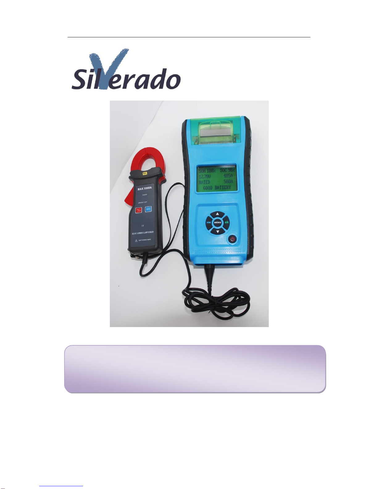
BST-380 Battery System Tester
User's Guide

User's Guide of BST-380 Battery System Tester
2/ 29
CONTENT
CHAPTER 1 PRODUCT SUMMARY 4
1.1 PRODUCT PROFILE 4
1.2 PRODUCT FUNCTION 5
1.3 TECHNICAL PARAMETER: 6
1.4 WORKING ENVIORNMENT REQUIREMENT 6
CHAPTER 2 TESTER STRUCTURE 7
CHAPTER 3 OPERATION 8
3.1 PRE-TEST 8
3.1.1 CONNECT TESTER 8
3.1.2 KEY DESCRIPTION 8
3.1.3 CONNECT CURRENT CLAMP 9
3.2 TESTER STARTUP 10
3.3 BATTERY TEST 11
3.3.1 IN-VEHICLE OR OUT-OF-VEHICLE 11
3.3.2 SELECT BATTERY CHARGE STATE 12
3.3.3 SELECT BATTERY TYPE 13
3.3.4 BATTERY SYSTEM STANDARD AND RATING 14
3.3.5 BATTERY TEST RESULT 14
3.4 CRANKING TEST 17
3.5 CHARGING SYSTEM AND RECTIFIER DIODE TEST 18
3.6 CLIENT NUMBER INPUT 20
3.7 24V SYSTEM TEST 21
3.8 ADDITIONAL FUNCTION 21
3.8.1 VIEW RESULTS 22
3.8.2 PRINT RESULTS 22
3.8.3 VOLTMETER 23
3.8.4 AMMETER 23
3.8.5 THERMOMETER 23
3.8.6 THERMOMETER UNIT CHOICE 23
3.8.7 QC MODE 24
3.8.8 LICENSE PLATE NUMBER INPUT FUNCTION 23
3.8.9 SET LANGUAGE 24
3.8.10 SET DATE AND TIME FORMAT 24
3.8.11 DATE AND TIME ADJUSTMENT 25
3.8.12 SET USER INFOMARTION 26
3.8.13 SCREEN LIGHTADJUSTMENT 26
3.8.14 SET PRINTER DEFINITION 26

User's Guide of BST-380 Battery System Tester
3/ 29
3.8.15 STANDBY POWER FUNCTION 28
CHAPTER 4 DAILY MAINTENANCE 28
4.1 ELIMINATE COMMON FAULT 28
4.1.1 SCREEN NOT LIGHT 28
4.1.2 PRINTER COMMON FAULT 28
4.1.3 CURRENT CLAMP COMMON FAULT 28
4.2 REPLACE INTERNAL BATTERY 28
CHAPTER 5 WARRANTY CLAUSE 29

User's Guide of BST-380 Battery System Tester
4/ 29
Chapter 1 : Product Summary
1.1 Product Profile
BST-380 Battery System Tester adopts currently the world's most advanced
conductance testing technology to easily, quickly and accurately measure the
actual cold cranking amps capability of the vehicle starting battery, healthy
state of the battery itself, and common fault of the vehicle starting system and
charging system, which can help maintenance personnel to find the problem
quickly and accurately, thus to achieve quick vehicle repair.
1. Test all automotive cranking lead acid battery, including ordinary lead acid
battery, AGM flat plate battery, AGM spiral battery, and Gel battery, EFB
battery etc.
2. Directly detect bad cell battery.
3. Polarity reverse connection protection, reverse connection will not damage
the tester or affect the vehicle and battery.
4. Directly test the battery with loss of electricity, no need to full charge before
testing.
5. Testing standards include currently the world's majority of battery
standards, CCA, BCI, CA, MCA, JIS, DIN, IEC, EN, SAE, GB.
6. Support multi-languages, customer can select different language package,
which includes: Chinese Simple, Chinese Traditional, English, Japanese,
Russian, Spanish, French, Italian, German, etc. Other languages can also
be customized according to user's need.
7. With common additional functions, such as voltmeter, ammeter,
thermometer, even as standby power for ECU.
8. Store 100 groups of test data for check and print.

User's Guide of BST-380 Battery System Tester
5/ 29
1.2 Product Function
Main functions of BST-380 Battery System Tester include: battery test,
cranking test, charging test and other additional functions.
Battery test is mainly targeted to analyze the battery healthy status to
calculate the actual cold cranking capability of the battery and the aging extent,
which provide reliable analysis evidence for the test and maintenance of the
battery.It notifies the user to replace battery in advance when the battery is
getting aged.
Cranking test is mainly to test and analyze the starting motor. Through
testing the actual required cranking current and cranking voltage of the starting
motor, it can find out whether the starting motor works fine.There are several
reasons why the starting motor is abnormal: lubricating system fault causing
the starting loaded torque increasing or rotor friction of the starting motor
causing the increasing friction of the starting motor itself.
Charging test is to check and analyze the charging system, including
generator, rectifier, rectifier diode, etc., thus to find out whether the output
voltage of the generator is normal, the rectifier diode works fine and the
charging current is normal.Suppose one of the above mentioned parts is not in
normal situation, it will lead to over charge or incomplete charge of the battery,
thus the battery will be quickly damaged and also greatly shorten the using life
of other loaded electrical appliance.
Additional functions include:
View test result, print test result, voltmeter, ammeter, thermometer and
temperature compensation, thermometer unit choice, QC mode, client code
setting, set language, set date and time format, date and time adjustment, set
user info, screen light adjustment, set printer definition, standby power
function.

User's Guide of BST-380 Battery System Tester
6/ 29
1.3 Technical Parameter
1) Cold Cranking Amps Measure Range:
Measure Standard
Measure Range
CCA
100-2000
BCI
100-2000
CA
100-2000
MCA
100-2000
JIS
26A17--245H52
DIN
100-1400
IEC
100-1400
EN
100-1400
SAE
100-2000
GB
100-1400
2) Voltage Measure Range:1.0-30VDC.
3) Current Measure Range:0-900A DC/AC.
4) Temperature Measure Range:-18°C - +70°C.
1.4 Working Enviornment Requirement
Working Environment Temp.: -20°C-60°C
It is applicable for automotive manufacturers, automotive maintenance and
repair workshops, automotive battery factories, automotive battery distributors,
and educational organizations, etc.
User's Guide of BST-380 Battery System Tester
7/ 29
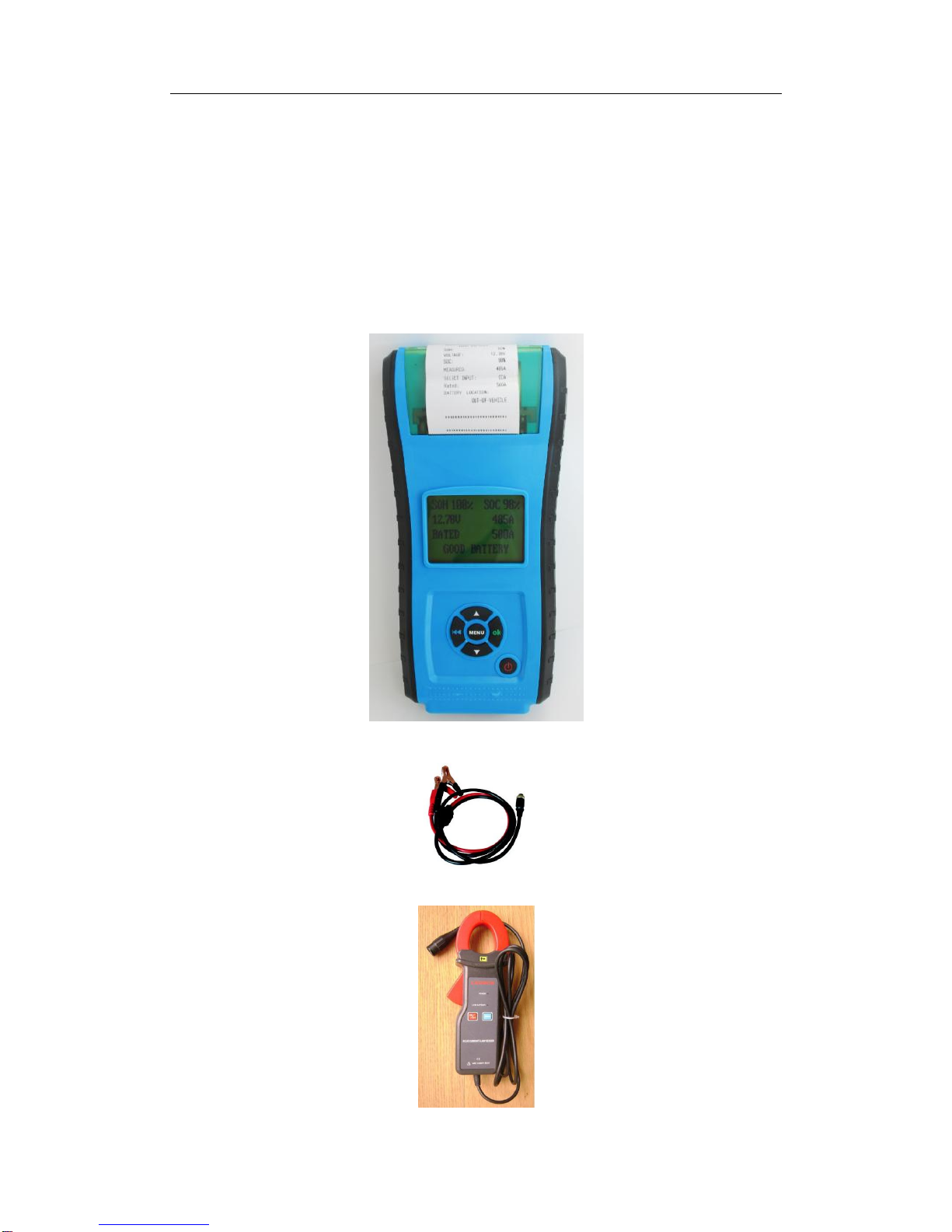
Chapter 2: Tester Structure
BST-380 mainly consists of battery tester main unit, testing cables and
current clamp.
BST-380 Battery System Tester main unit cover is made of ABS
acid-resistant plastic.
Removable testing cables
Removable current clamp meter

User's Guide of BST-380 Battery System Tester
8/ 29
Chapter 3: Operation Procedure
3.1 Pre-Test
3.1.1 Connect Tester
●Before test, clean battery poles with metal wire brush and alkaline cleaner
to avoid the tolerance caused by oil and dust to the test result.
●For Group 31 or side-installed battery, connect and fix the terminal wiring
connector. Otherwise, inaccurate test result will be caused due to wrong
installation or dirty or bad wiring connectors.
●While testing, ensure none of the in-vehicle electrical appliance is on,
doors are closed and the ignition key is in OFF status.
●Connect the red test clamp with battery anode and the black test clamp
with cathode.
Shake the clamps back and forth to make sure they are well connected.
Tester requires the two clamps are well connected with the battery poles,
otherwise, the test cannot go on. When enter the battery test program, screen
prompts "Check Connection" (See below picture).Do clean the poles and
re-connect in the right way.
Tester has reverse connection protection function. When clamps are
reversely connected, tester will prompt "Reverse Connection" (See below
picture), but it damages neither the tester nor the automotive load.
NOTE: For parallel connected batteries, break off the cathode connection first,
then do single test to each battery.Suppose cathode connection is not cut off,
there will be error in test result.

User's Guide of BST-380 Battery System Tester
9/ 29
3.1.2 Key Description
●Up and Down keys
Select upwards or downwards via white UP and DOWN keys.
●Return key
Return to previous menu via blue RETURN key.
●OK key
Confirm the selection via green OK key
●MENU key
Enter additional function program via MENU key.
●Power key
Turn on/off the tester.(Refer to 3.2 Tester Startup)

User's Guide of BST-380 Battery System Tester
10 / 29
3.1.3 Connect Current Clamp
To test cranking amps and charging current, first connect the current
clamp before startup, then turn on the current clamp power swtich.
After tester startup, current clamp is able to work.
Press the reset key of the current clamp and connect the current clamp
jaw to the anode wiring between the battery to be tested and the generator.
As the minimum width of the current clamp jaw is only 28mm, choose the
connection cable or connection pole with diameter less than 28mm to test.
Otherwise, the current clamp jaw cannot close completely.
NOTE: 1. Current clamp jaw must close to avoid test tolerance.
2. Current clamp uses 9V alkaline battery. Turn the clamp
power off after using the current clamp.
3. Before testing the current, take off the current clamp from the
battery positive connection cable, and reset.
3.2 Tester Startup
Tester will start up after pressing the power key, and display the customized
logo interface (Default voltmeter is ON) refer to figure 1.
Figure 1, Startup Interface with Voltmeter On
At the bottom left of the startup interface, " " shows the real time capacity of the
internal 9V battery. When the capacity of the 9V battery is not sufficient, do
replace it in time to avoid effect to the usage of the additional functions.
By default, at the middle bottom of the startup interface, it displays the
voltmeter value, which can be used as DC voltmeter.DC voltmeter measure
range is 1.0-30VDC.(Caution: Over this measure range, it will damage the
tester.)
Voltmeter function can be set as "ON/OFF" in the voltmeter under Additional
Functions.
When Voltmeter is ON and no other operations after tester startup, screen will
show the startup interface all the time. In this situation, it can be used as a DC
Voltmeter.When OK key is pressed, tester enters the battery test program.
Press MENU key, it enters additional function program.
When Voltmeter is OFF, screen shows the startup interface as below figure 2.

User's Guide of BST-380 Battery System Tester
11 / 29
After 2seconds, it automatically enters the battery test program.Press MENU
key within this 2 seconds, it enters additional function program.
Figure 2, Startup Interface with Voltmeter Off
3.3 Battery Test
After entering battery test program, tester displays the tester model and
version approx. 2 seconds, see figure 3
Figure 3, Interface with tester model and version
The bottom line of the interface shows the current date and time, whose
format can be edited and adjusted in theAdditional Functions. For details, refer
to Additional Function 3.8.10 "Set Date and Time" and 3.8.11 "Date and Time
Adjustment".
Tester will display the following contents in a sequence, select
accordingly.
3.3.1 IN-VEHICLE or OUT-OF-VEHICLE
Press UP/DOWN key to select the battery location, in vehicle or out of vehicle,
then press OK key to confirm.
1) IN-VEHICLE means battery is connected with vehicle generator or vehicle
electrical appliance.

User's Guide of BST-380 Battery System Tester
12 / 29
When surface charge detected by the tester, it prompts "SURFACE CHARGE,
TURN LIGHTS ON".
Turn lights on as prompted to eliminate battery surface charge, tester will then
display the following messages in a sequence:
Now the tester detects the surface charge has been eliminated, turn lights off
as prompted, then press OK key. The tester will recover automatic test.
2) OUT-OF-VEHICLE means battery is not connected with any of the vehicle
loaded, i.e. battery connection is cut off.
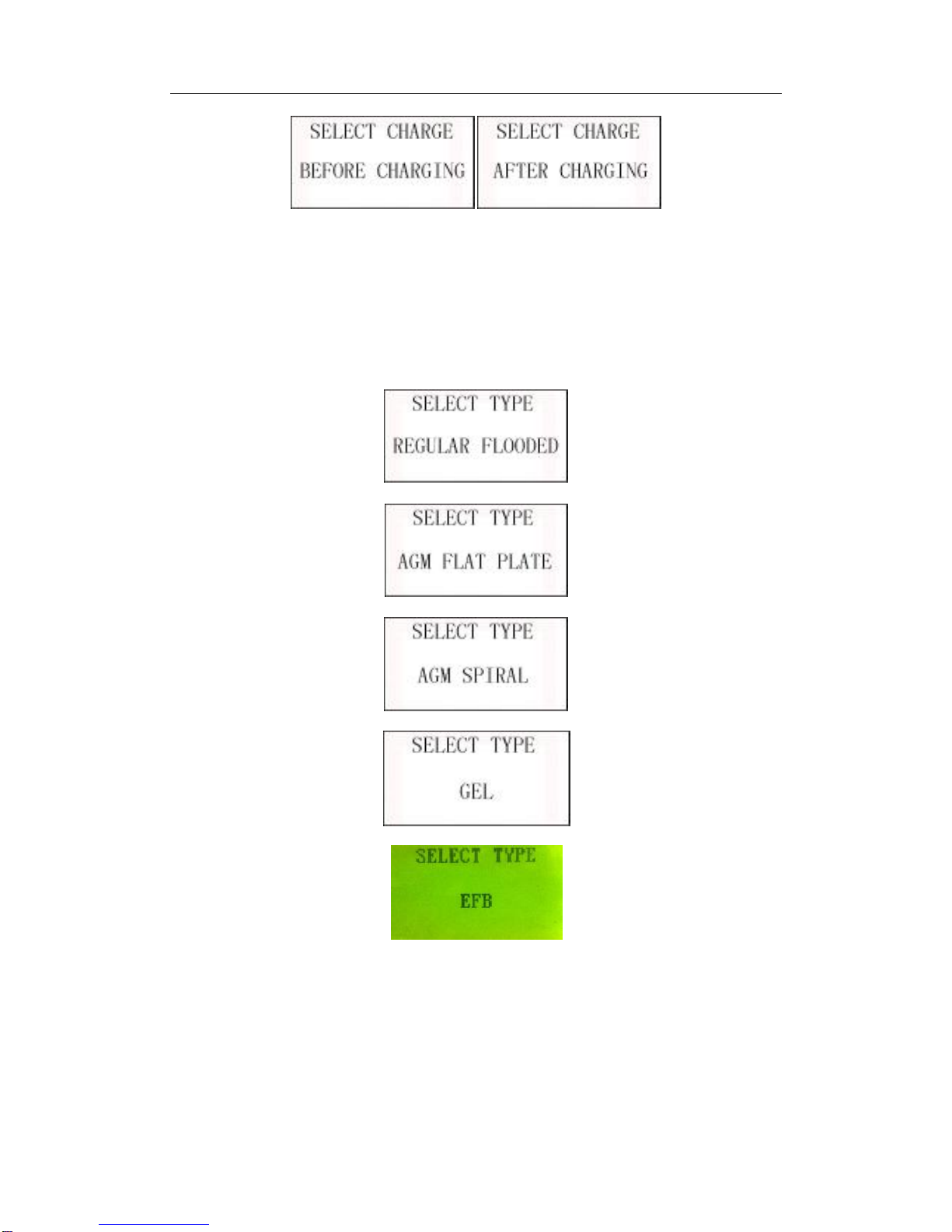
3.3.2 Select Battery Charge State
After selecting the battery location, tester will prompt to select the battery
charge status, i.e. Before Charge orAfter Charge.
Press UP/DOWN key to select battery charge status, then press OK key to
confirm. In this way, it ensures a more accurate test result.
NOTE: In Vehicle, select Before Charge for Cold Vehicle and After Charge for
Hot Vehicle.
User's Guide of BST-380 Battery System Tester
13 / 29
3.3.3 Select Battery Type
After the battery charge status selected, tester will prompt to select battery
type, i.e. Regular Flooded, AGM Flat Plate or AGM Spiral, and Gel battery,EFB
battery .Press UP/DOWN key to select battery type, and press OK key to
confirm.
When it's IN-VEHICLE test, battery installation way shall also be selected, e.g.
TOP, SIDE or REMOTE (This selection is no need for OUT-OF-VEHICLE),
then press OK key to confirm.REMOTE is adopted for some in vehicle battery
which is too tightly installed to use the test clamps to connect the battery poles.

User's Guide of BST-380 Battery System Tester
14 / 29
NOTE: For REMOTE test, there will be a little tolerance. For any doubt, take
off the battery and select "OUT-OF-VEHICLE" to re-test.
3.3.4 Battery System Standard and Rating
BST-380 Battery System Testerwill test each battery according to the selected
system and rating.
Use UP/DOWN key to select according to the actual system standard and
rating marked on the battery. See in the below picture, the arrow indicated
location.

User's Guide of BST-380 Battery System Tester
15 / 29
CCA:Cold Cranking Amps, specified by SAE&BCI, most frequently used value
for starting battery at 0°F (-18°C)
BCI: Battery Council International standard
CA: Cranking Amps standard, effective starting current value at 0°C
MCA: Marine Cranking Amps standard, effective starting current value at
0°CJapan Industrial Standard, displayed on the battery as combination of the
numbers and letters, e.g. 55D23,80D26.
DIN:German Auto Industry Committee Standard
IEC:Internal Electro technical Commission Standard
EN:European Automobile Industry Association Standard
SAE: Society of Automotive Engineers Standard
GB:China National Standard.
Rating range as following:
Measure Standard Measure Range
CCA 100-2000
BCI 100-2000
CA 100-2000
MCA 100-2000
JIS 26A17--245H52
DIN 100-1400
IEC 100-1400
EN 100-1400
SAE 100-2000
GB 100-1400
Input correct test standard and rating, press OK key, tester starts to test,
and dynamic interface "TESTING" prompted. See below.
It takes around 3 seconds to display the battery test result.
User's Guide of BST-380 Battery System Tester
16 / 29
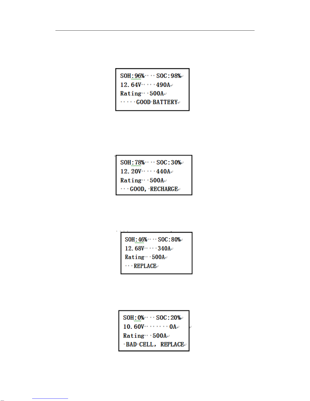
3.3.5 Battery Test Result
Battery test result includes 5 types as following:
1) Good Battery
The battery is without any problem, please be relaxed to use!
NOTE: SOH means State of Health.
SOC means State of Charge.
2) Good, Recharge
Good battery but low current, recharge before using.
2) Replace
The battery is near to or already reached the end of the using life,
replace battery, otherwise, bigger danger will be followed.
4) Bad Cell, Replace
Battery interior damaged, broken cell or short circuit, replace battery.
User's Guide of BST-380 Battery System Tester
17 / 29
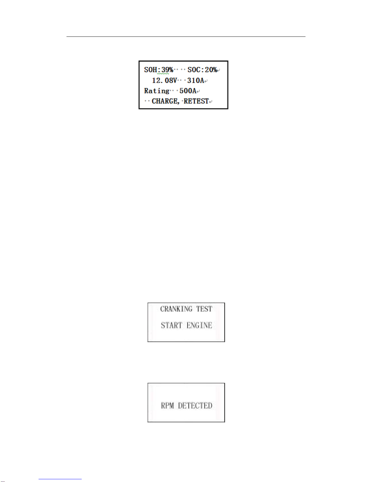
5) Charge, Retest
Unstable battery shall be recharged and retested to avoid error.If same test
result appears after recharge and retest, the battery is regarded as damaged,
replace the battery.
NOTE: If "Replace" resulted from IN-VEHICLE mode, it might be the reason
that vehicle cable is not well connected with the battery.Ensure to cut off the
cable and retest the battery under OUT-OF-VEHICLE before making a
decision to replace battery.
NOTE: After testing, if need to return, press RETURN key to directly return to
the startup interface.
After battery test:
If it is "OUT-OF-VEHICLE" test state, press OK key, it will print the test result.
If it is "IN-VEHICLE" test state, press OK key will bring to Cranking Test.
3.4 Cranking Test
Connect with current clamp in advance. Under bad connection, tester will
not test the actual cranking amps accurately.
Refer to 3.1.3 for current clamp connection.
Starting the engine as prompted, tester will automatically complete the
cranking test and display the result.
User's Guide of BST-380 Battery System Tester
18 / 29
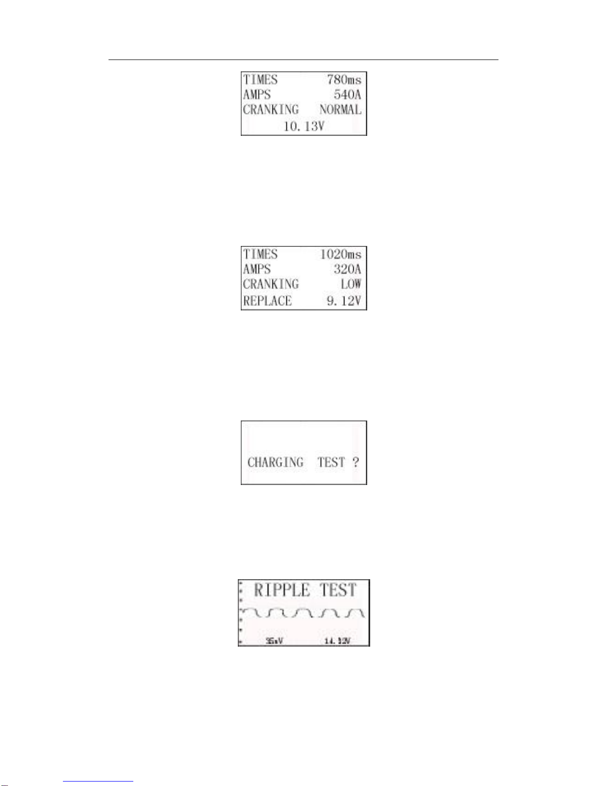
Normally, cranking voltage value lower than 9.6V is regarded as abnormal,
higher than 9.6V is OK.
Test result of the tester includes actual cranking voltage, actual cranking amps,
and actual cranking time.
When cranking test is abnormal, battery test result will also be displayed at the
same time.See below picture:
This is for the convenience of the maintenance personnel to quickly know the
whole state of the starting system according to the data.
After testing finished, do not shut down the engine, press OK key to enter
Charging Test.
3.5 Charging System and Rectifier Diode Test
When enter the charging test, tester will prompt "Charging Test?"
Press OK key again to start the charging test.
NOTE: Do not shut down the engine during the test.All electrical appliance and
device are in OFF state.Turn on/off any electrical appliance in the vehicle
during the test will affect the accuracy of the test result.
Tester will do the following tests in a sequence:
For ripple test, tester will display the real time ripple and meanwhile, shows
ripple volt and charging volt values at the bottom line.
It takes approx. 6 seconds for the ripple test.
User's Guide of BST-380 Battery System Tester
19 / 29
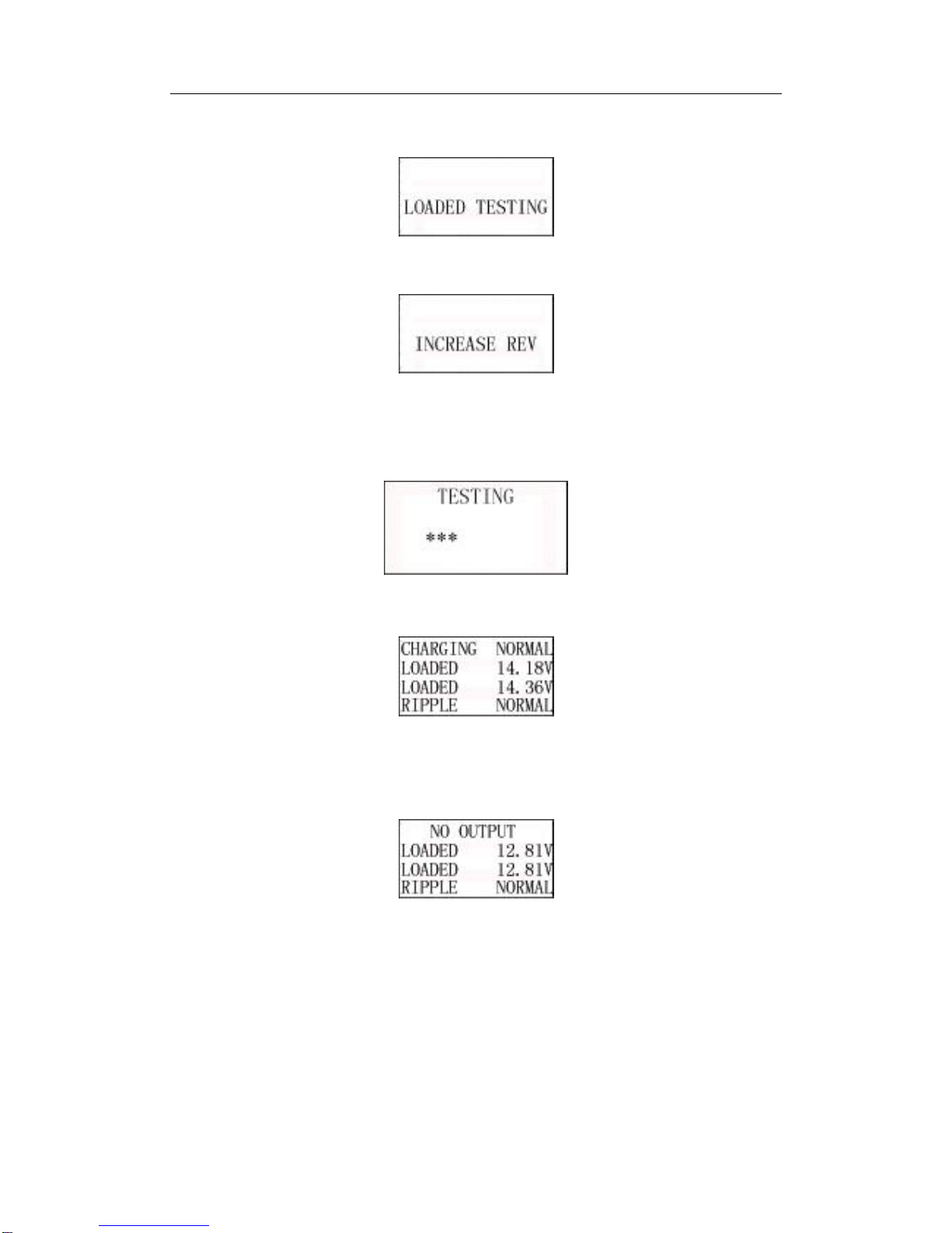
After the ripple test, tester will automatically start the loaded voltage test.See
below picture:
Loaded Volt Test takes approx. 3 seconds, then it hints "Step on accelerator to
increase engine rotating speed".See below picture:
Operate accordingly to increase the engine rotating speed to 3000turns or
above, and keep for 5 seconds.
Tester starts the charging volt test after increase rev detected.See below
picture:
After the test finished, tester displays the effective charging volts, ripple test
result and charging test result.See below picture:
NOTE: If no increase rev detected, it shall be the fault of generator regulator or
connection with battery failed.Tester will try 3 times to further detect, if still
failed, it will skip the increase rev detect and the test result displays "No Volt
Output".See below picture:
Check the connection between generator and battery, then retest.
Charging Test Result:
1) Charging Volt: Normal
Charging system shows the generator output normal, no problem detected.
2) Charging Volt: Low
Charging volt of the charging system is low.
Check drive belt of the generator whether slip or running off. Check the

User's Guide of BST-380 Battery System Tester
20 / 29
connection between generator and battery is normal or not.
If both of the drive belt and the connection are in good condition, follow the
manufacturer's suggestion to eliminate generator fault.
3) Charging Volt: High
Generator output volt is high.
Since most of the vehicle generators are using internal regulator, the generator
assembly has to be replaced.(Some old style cars are using external regulator,
then directly replace the regulator.)
The normal high volt of the voltage regulator is maximum 14.7±0.5V.If charging
volt is too high, it will overcharge the battery. Therefore, the battery life will be
shortened and troubles will be caused.
4) No Volt Output:
No generator volt output is detected.Check the generator connection cable,
the drive belt of generator and engine whether normal or not.
5) Diode Test:
Through the test of charging current ripple, tester will find out whether the
diode is normal or not.When ripple volt is too high, it proves at least one diode
is damaged. Check and replace the diode.
Till now, all tests have been done
If client code setting function is off, press OK key again, it prompts "Print
Result?", press OK key to print.If client code setting function is on, press OK
key again, it prompts "Print Result?", press OK key to input client code.After
client code input, press OK key again, it prompts "Print Result?", press OK key
to print.
3.6 Client code Input
Client code in a sequence, 1nd to 7th digits are letters or numbers.When
press UP/DOWN keys, numbers and letters will be scrolling displayed, select
the number or letter needed, press OK key to confirm and carry on the input for
next digit. DEFAULT is
For example, to input "BA8888".
Press UP/DOWN key to select the first Chinese character "BA", press OK to
finish the first digit input.
Table of contents


