SCUDO NU-022 Wiring diagram

Installation Instructions & User Guide
Thermostatic Recessed Dual Control Shower Valve
Models Covered: NU-022 / NU-023 / NU-024
NU-028 / NU-029 / NU-030
IMPORTANT: Please keep these instructions for future reference.

Contents:
Thank you for choosing Scudo. We have designed this product with our customers in
mind. To ensure that it works as we intended, it needs to be tted by a professional.
These tting instructions give you all of the information you need for installation. Do not
hesitate to call our customer service team on 0330 124 7290 for assistance.
Important Safety Information...................................................
General Information.................................................................
Prior to Installation...................................................................
Installation................................................................................
Shower Valve .........................................................
Wall Outlet ............................................................
Operating the Shower..............................................................
Maintenance.............................................................................
Adjusting the Temperature.......................................................
Troubleshooting........................................................................
1
2
3
4
5
6
7
8
9
10

Important Safety Information:
• Please thoroughly read this set of instructions and retain for future use.
• All products manufactured and supplied by Scudo are safe provided they are installed,
used correctly and receive regular maintenance in accordance with these instructions.
• To safely install this product please employ the the services of an experienced
plumber.
• These ttings must meet the requirements, and be installed in accordance with the
Water Supply (Water Fittings) Regulations 1999 and Scottish Byelaws 2004.
• Check there are no missing or damaged parts before installation.
• Before starting any installation please consider the following:
• Before drilling into walls, check that there are no electrical wires, cables or
water supply pipes. This can be checked with a electronic detector
• When using power tools do not forget to: - Wear appropriate PPE
- Unplug equipment after use
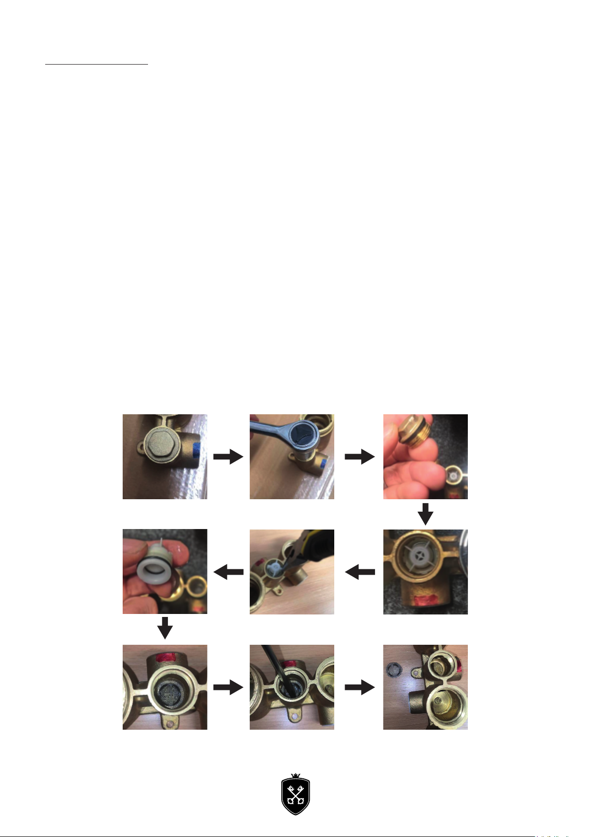
• Warning: Before installing the new shower valve, it is essential that you
thoroughly ush through the pipework in order to remove any remaining swarf,
solder, etc. Failure to carry out this procedure could cause problems or damage
to the workings of the shower valve.
• Advised to install appropriate isolation to the inlet feeds.
• Do not block the ow of water from the showerhead by placing it (smoothering it) on
your hand or any other part of your body or foreign object.
• Do not crush or kink the shower hose, this could damage the hose causing leaks.
• Warning: Do not operate this product if you suspect it is frozen. Do not site
mixing valve where it might be subjected to freezing conditions.
• These shower valves must not be modifed in any way as this will invalidate the
guarantee.

General Information:
This product has been tested to the Water Regulations Advisory Scheme (WRAS) and satises
the requirements of the Water Supply (Water Fittings) Regulations 1999 and current bylaws.
BS7600 recommends the temperature of stored water should never exceed 65ºC. A stored
water temperature of 60ºC is considered sufcient to meet all normal requirements and will
minimise the build up of lime scale in hard water areas.
If the shower valve is installed at low pressure (tank fed), then the minimum distance from the
highest installed position of the showerhead to the underside of the cold tank should be at
least 1 metre to ensure adequate performance. It is recommended low pressure systems are
pumped to ensure minimum 0.5 bar of pressure.
Note: Nominally equal (balanced) inlet supply pressures are recommended for
optimum performance.
This shower valve should be installed in compliance with the Water Supply (Water
Fittings) Regulations1999 and the Scottish Bylaws 2004.
Recommened Usage
Domestic
Light Commercial
Heavy Commercial
Health Care

Pack Contents: NU-022 / NU-023 / NU-024
1. Concealed Dual Outlet x1
2. Shower Wall Arm x1
3. Handle Shrouds x2
4. Concealed Plate 1x
5. Valve Body Fixings x4
6. Handle x2
7. Insert x1
8. Temperature Control x1
9. Wall Bracket & xings x1
10. Slider Bracket x1
11. Wall Outlet/Riser Support x1
12. Riser Rail x1
13. Handset x1
14. Drench Head x1
15. 1/2 inch Washer x3
16. Ball Fixings Washer x1
17. Hose x1
1
2
3
45
6
7
8
9
10
11
12
13
1416
15
15
15
17

Pack Contents: NU-028 / NU-029 / NU-030
1. Concealed Dual Outlet x1
2. Shower Wall Arm x1
3. Handle Shrouds x2
4. Concealed Plate 1x
5. Valve Body Fixings x4
6. Handle x2
7. Insert x1
8. Temperature Control x1
9. Wall Outlet/Handset mount x1
10. Handset x1
11. Drench Head
12. 1/2 inch Washer x3
13. Ball Fixings Washer x1
14. 1/2” Hose x1
4
1
6
5
2
1113
12
10
12
8
3
7
12
9

Installation: Shower Valve
This shower valve is designed for installations
where a recessed valve is already installed in
the wall cavity and is to be replaced, or for new
installations.
Before Installation
Flush through the pipework to ensure removal of
any debris. Turn off the mains water supply and
close any isolating valves.
1. Attach shower valve to wall
Place the shower valve in the required position and
mark the centres of the xing holes onto the wall.
Warning: Please check for any hidden pipes and
cables before drilling holes in the wall.
Drill suitable holes and insert the wall plugs.
Securely attach the shower valve to the wall using
the screws supplied.
2.Connect water supply pipes
Insert 15mm hot and cold water supply pipes into
the inlet connections and tighten nuts, ensuring
the olives are tted.
3.Plumb in outlets
Insert 15mm pipework into the top outlet and
plumb into the users chosen product. Ensure the
olives are tted when tightening the nuts.
Important: Water supplies to the mixer must
be with hot on the left and cold on the right
when viewed from the front.
Wrap PTFE tape around thread.
Avoid over wrapping.
3/4” BSP (Not Included)

Installation: Shower Valve
4. Finish wall surface
Plasterboard and tile the cavity wall. After cut down plastic case to be ush against the wall. Fit
the shrouds after this process.
5. Fit concealing plate and handles
Run a bead of waterproof silicon sealant around the
inner edge of the concealing plate.
Slide the concealing plate onto the shower valve
control handles and apply rm pressure to ensure to
silicon sealant spreads.
6. Fit handles
Push the spline adaptors onto the valve spindles.
Push the handles onto the spline adaptors and secure
by tightening the grub screw and push-t the cap into
position.
Fit Plaster Tile Cut & Shrouds

Installation: Wall Arm and Drench Head
Wrap PTFE Tape around the thead on the wall arm and screw into the back plate elbow.
Screw drench head onto the wall arm.
Operating the Shower:
OFF
FUNCTION 1 FUNCTION 2
A
B
COLDHOT
1. Two outlet diverter
This outlet allows the user to divert the ow of water from one product to another.
Turn the handle one way or the other to turn the ow of water on to your chosen product.
To turn the ow of water off turn the handle back to the centre.
2. Temperature control
Adjustable temperature control. Turn the handle clockwise for a cooler temperature.
Turn the handle anti-clockwise for a hotter temperature.

Maintenance
General Cleaning
Your tting has a high quality nish and should be treated with care to preserve the visible
surfaces. All surfaces will wear if not cleaned correctly, the only safe way to clean your product
is to wipe with a soft damp cloth.
Stains can be removed using washing up liquid. All bath cleaning powders and liquids will
damage the surface of your tting, even the non-scratch cleaners.
Cartridge Maintenance
We advise that the shower valve is regularly serviced in hard water areas to maintain the ow
of water.
Isolate both hot and cold water supplies to the shower valve by either:
• Turning the water supply off at the
mains stopcock or
• Turning off the isolation valves to the
shower valve.
Cleaning the Shower Filter:

Maintenance
a. Remove the cold water outlet hexagonal nut (4) using a socket wrench.
b. Remove cartidge.
c. Clean mesh with warm soapy water.
d. Repeat the same for warm water outlet (2)
Adjusting the Temperature
The shower valve has been factory set to 42ºC with equal (balanced) hot and cold water
supply pressures, with the hot water supply at 65ºC.
If your operating conditions are different from those above, the outlet water temperature may
differ from the factory setting.
If required the shower valve can be re-calibrated to suit your own temperature requirements.
Set the temperature control to the maximum setting and check the temperature of the water
with a thermometer. If the temperature is not correct, re-calibrate the shower valve:
1.Remove the temperature handle but do not remove the plastic temperature stop.
2.Turn the spline clockwise to decrease the temperature and anticlockwise to increase the
temperature. Check the temperature and adjust until you achieve the required temperature.
3.Replace the temperature handle ensuring it is tted back into the maximum position.

Troubleshooting
Symtom Cause Remedy
No ow or low ow rate and /
or varying temperatures.
Check showerhead, hose and lters
for any blockage.
Clean as necessary, refer to
maintenance page.
Partially closed stop or service valve
in water supply pipework to the
shower valve.
Open stop or service valve.
Instantaneous water haeter cycles
on and of as the ow rate or
pressure is too low.
Increase water ow rate or pressure
through system, Contact the boiler
manufacturer.
Head of water is below the
minimum distance required.
Raise the cistern or t a negative
head shower booster pump.
Inlet lter is partially blocked. Clean or replace, ush through
pipework before retting.
hot or cold water being drawn
off elsewhere causing pressure
changes or instantaneous boiler
temperature changes.
Refer to Boiler troubleshoot
Airlock or partial blockage of the
pipework.
Flush through pipework to ensure
removal of debris and any airlocks.
No hot or cold water
reaching the shower valve.
Check hot and cold feeds (the valve
will shut down if either the hot or
cold supply fails).
Only hot or cold water from
the shower valve outlet.
Partically closed stop or service
valve in water supply pipework to
the shower valve.
Open stop or service valve.
Inlet lter is partially blocked. Clean or replace, ush through pipe-
work before retting.
Inlet water supplies are reversed
(hot to cold supply).
Check the connections are correct
way round. Hot on the left and cold
on the right when viewed from.
Rework pipework as nessessary
Water leaking from
showerhead.
This is normal for a short time after
turning it off.
Adjust angle of showerhead in hold-
er as necessary to vary drawing time.
Shower cartridge failing to close
fully, possibly due to water borne
debris.
Remove shower cartridge and check.
refer to Maintenance section before
dismantling shower valve.
Maximum water temperature
too hot or cold
Maximum water temperature set
incorrectly.
Reset maximum water temperature.
Refer to ‘Maximum Temperature
setting’ in Maintenance section and
‘Adjusting the Temperature’
Outlet water temperature too
hot / cold
Inlet lter is partially blocked Check inlet lters for any blockages
and as necessary.
Installation conditions outside
operating parameters.
Refer to Specication.
Service shower valve as
recommended.
Refer to ‘Maintenance’ section
Refer to ‘Adjusting the
Temperature’ section

Troubleshooting
Symptom Cause Remedy
Water temperature too cold -
Maximum water temperature
incorrectly set.
Hot water temperature is
less than 10ºC above the
required blend
temperature.
Adjust hot water temperature
or wait for water to reheat if
stored system is used.
Instantaneous water heater
not igniting because water
ow rate is too low.
Increase water ow rate
through the system. Check inlet
lters and clean or replace. Refer to
Maintenance section.
Contact the boiler manufacturer.

Notes:
Please use this space to add any notes you or your installer may have regarding the plumbing system or
installation of this product.

Notes:
Please use this space to add any notes you or your installer may have regarding the plumbing system or
installation of this product.
This manual suits for next models
4
Table of contents
Popular Control Unit manuals by other brands

Burlington
Burlington SP697 Installation instruction

VAT
VAT 615 Series Installation, operating, & maintenance instructions

LOVATO ELECTRIC
LOVATO ELECTRIC EXP1016 instruction manual

Fermax
Fermax SKYLINE LYNX DUOX Installer manual

Mesto
Mesto VAQ113 Installation maintenance and operating instructions

Boreal
Boreal WIFI2-B Installation, operating and servicing instruction