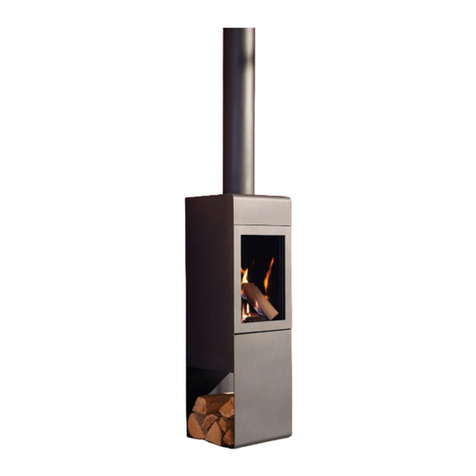
Sculpt SEGUIN MULTIVISION HYDRO 80 Operation manual

1
1. SPECIFICATIONS
2. PRELIMINARY INSTALL GUIDE
3. COMPONENTS LIST
4.0 INBUILT AGAINST COMBUSTIBLE WALL
5. INBUILT INTO ISLAND WALL
NON COMBUSTIBLE SURROUNDINGS
6. FREE STANDING INSTALL
7. OPERATION & MAINTENANCE
8. TEST RESULT
9. WARRANTY
SEGUIN
NOTICE TO INSTALLER:
These instructions must be left with the owner, who should keep them for future use.
4.1 MASONRY BRICK INSTALLATION
4.2 HEBEL INSTALLATION
4.3 SKAMOL: REFER TO SKAMOTEC 225 MANUAL
Multivision Hydro 80
INSTALLATION & USER GUIDE

2
COMPLIANCE PLATE AND SERIAL NUMBER.
The instructions in this manual are recommendations only, the distributor and manufacturer bears no liability to the interpretation of these instructions.

3
Thank you for choosing Sculpt Fireplaces as your heater of choice.
Your replace is the result of careful design, artisan engineering and safety tests.
If it is properly installed, used and maintained, you may be sure that you will have an outstanding
heating feature in your home for years to come.
We advise you to read through this guide in order to become acquainted with the installation
methods specic to your replace.
It is recommended that this replace be installed by a qualied and licensed trades professional.
You will nd in this guide the answers to most of your questions, should you require further
assistance we recommend you contact your retailer.
Before igniting your replace for the rst time, please carefully read this manual.
Follow @sculptreplacecollection on Instagram, SculptFireplaceCollection on Facebook and be
sure to post your latest masterpiece installed with the hashtag #sculptres.
We hope we’ve helped make you the envy of your friends this winter and for years to come.
From all of us,
Sculpt Fireplace Collection
CONGRATULATIONS!

4
IMPORTANT
*Heating capacity of the following appliances are a guide only and refers to areas with 2.4m ceilings
and 6 or more star rated buildings. Heating output may vary depending on factors such as building
characteristics, quality of insulation, type of rewood used and climate zone.
All dimensions shown are approximate. Check all dimensions accurately prior to installation. In line with
our policy of continuous improvement, we reserve the right to alter specications without notice.
All units comply and MUST be installed to Australian & New Zealand Standard AS/NZS 2918:2018.
When in use some parts may become hot. A suitable re guard is recommended where very young,
elderly or inrm are concerned.
ALL FIREPLACES IN THIS MANUAL CONFORM TO AUSTRALIAN AND NEW ZEALAND STANDARDS
AS/NZS 2918:2018 DOMESTIC SOLID FUEL BURNING APPLIANCES & AS/NZS 4012/4013(2014).
The instructions in this manual are recommendations only, the distributor and manufacturer bears no liability to the interpretation of these instructions.
© Copyright 2019 Sculpt Fireplaces Collection

5
1. SPECIFICATIONS
SEGUIN MULTIVISION HYDRO 80
Power for heating the room
Max. water working pressure
Weight
Average volume of ue gas
Average ue gas temp. at ue conduit
Volume of water jacket
Avg required chimney draught at nominal
thermal power
6.33 kW
1,5 bar
345 kg
20.05 g/s
302°C
21 Litres
12+2 Pa
665mm
1185mm
800mm
250mm
451mm
Thermal power
Facade
Glass door
Minimum ue height
Flue sizes
Includes hot air kit
Outside air kit
Warranty
Hearth dimensions
Nominal: 25.9kW Water System: 14.3kW
Clean frameless design (no trim)
Secure swing door
4.6m
250mm (active), 300mm, 350mm
A duct and register
Recommended for well insulated homes
10 year rebox warranty*
Minimum 500mm in front of any part of replace,
250mm on either side & 75mm thick
20/27F
26/34F
20/27F
20/27F
26/34F
26/34F
20/27F
20/27F
26/34F
20/27F

6
2. PRELIMINARY INSTALL GUIDE
It is the users duty to make themselves aware of and apply all national or more restrictive local
standards and instructions (AS/NZS 2918:2018).
IMPORTANT
Prior to unpacking and installation check that the appliance has not been damaged during transport.
Ensure you check the glass, the door(s), the damper operation and the door locking mechanism
Before any work is carried out, as per local and national regulations and laws, this appliance MUST be
installed by a licensed professional as per Australian and New Zealand Standards 2918:2018.
IMPORTANT WARNING
It is strictly forbidden to use any combustible materials (ie; wooden framing, plaster, etc) near or around
this appliance. Any exception from this rule is a health and safety hazard which will result in a non-
compliant installation and a void of warranties.
Electrical cables and components must not be placed in the vicinity of the appliance as it is a re
hazard.

7
For the installation and use of this appliance, the tter and the user should strictly adhere to local
and national regulations in addition to Australian & New Zealand Standards AS/NZS 2918:2018. The
installer should comply with the instructions and recommendations detailed in this manual. Safety and
operation of the replace is directly dependent thereon. The liability of the manufacturer can neither be
retained nor assured following failure of installation or incorrect use which does not comply with AS/
NZS 2918:2018.
As each installation is unique, a qualied and licensed trades professional should take all required
preliminary precautions depending on the technical elements inherent to each job.
In-observance of the assembly instructions in conjunction with AS/NZS 2918:2018 entails the liability
of the person who carries it out.
As a result of faulty assembly, irrational use of parts or additional components that were not supplied
by the manufacturer, and/or modifying of the appliance or components will result in inferior or unsafe
operation. Should this occur the manufacturer bears no liability, and will result in a null and void product
warranty.
PRELIMINARY INSTALL INFORMATION
All images and diagrams in this manual are for installation reference purposes only and are not to
scale, the distributor and manufacturer bears no accuracy of these images and accepts no liability. The
purpose of these images and diagrams is to act as a guide in conjunction with the written components,
and are NOT to be used to instruct independently. The order of steps listed in this manual are
recommendation only.
It is strongly recommended that the licensed trade professional who is performing the installation of
this appliance, completely read and comprehend all instructions in this manual prior to proceeding.
Sculpt Fireplaces & Seguin reserves the right to change these specications without prior notice.
PLEASE READ PRIOR TO INSTALL
For reasons of quality control, some of our appliances are delivered assembled. Some lighter units
are directly assembled, puttied and sealed. Whilst other heavier models are delivered with the gather
unassembled to make it easier for transportation. Gasket and refractory putty is provided with these
units, a slip is placed in all the non-jointed replace in order to attract attention. Assemble the gather
on the top of the rebox, the putty should be widely spread and then wiped.
ACCEPTABLE VARIANCE ALLOWANCE
Due to the production of these hand assembled and manufactured replaces, there is an acceptable
allowance of 3-5mm variance of the unit, including the door frame. This variance in production is non-
claimable under any warranties.
HEAT RESISTANT MATERIALS
Heat resistant materials must meet AS/NZS 2918:2018 clause 1:4.27 a material with an allowable
service temperature of 600° Celsius or greater.
EXPOSURE TO ELEMENTS
Seguin replaces are exclusively designed as indoor heating appliances, should the replace (or part
there of) be in contact with the outside elements including rain, snow, direct sunlight, excessive winds,
etc. Then the damage sustained thereon will not be covered under the manufacturer or distributor
warrantie(s). Please consider prior to installing your replace exposed to outside elements.
2. PRELIMINARY INSTALL GUIDE

8
The diagrams depicted in this manual feature the installation procedure for the Seguin Super 9, while
this may not be the same unit as your appliance, the process of the installation procedure across the
range is standardised & should be adapted to suit your unit requirements. Depending on your appliance
and installation scenario elements may vary including frame, cavity and dimensions.
No two installations follow the exact same procedure, as no two homes are alike, it is important
to work with your professional installer, architect and builder to structure a custom installation that
suits your scenario. Further questions regarding your appliance and its installation should be directed
towards your supplier, and nally Sculpt replace Collection.
All images and diagrams in this manual are for installation reference purposes only and are not to
scale. The distributor and manufacturer bears no accuracy of these images and accepts no liability. The
purpose of these images and diagrams is to act as a guide in conjunction with the written components
and are NOT to instruct independently. The order of these steps are a recommendation only.
It is strongly recommended that the licensed trade professional who is performing the installation of
this appliance, completely read and understand all instructions in this manual prior to proceeding.
Sculpt Fireplaces & Seguin reserves the right to change these specications without prior notice.
IMPORTANT: For possibly replacing the flue or for a technical intervention, the installation of an
access hatch on the replace cavity is essential.
ACCESS HATCH:
PLEASE READ PRIOR TO INSTALL
2. PRELIMINARY INSTALL GUIDE

9
FRESH AIR INLET IS ESSENTIAL FOR ALL INSTALLATIONS
The air inlet is essential for installation and the proper function of the appliance. The fresh combustion air inlet
must be a minimum 300cm2and ideally positioned (see point A & B on diagram).
Airways must be clear and checked regularly to ensure air circulation is correct otherwise it may cause over
heating.
PLEASE READ PRIOR TO INSTALL
Clearance Gap 50mm
Firebox
Non combustible wall
Hot air grid
Air vents
False Ceiling
A
B
2. PRELIMINARY INSTALL GUIDE

10
PRELIMINARY INSTALL GUIDE
1. ASSEMBLING OF MOVABLE PARTS OF THE FIREPLACE INSERT
Your Multivision Hydro 80 replace insert compromises of at least two movable parts which can be
displaced during transportation:
1.1. BAFFLE (PROTECTIVE DEFLECTION PLATE)
The baffle plate is a heat deflector that deflects the heat back in to the combustion chamber and
protects the interior of the appliance and flue against the direct exposure to the flames. The baffle plate
for this appliance is provided as a seperate element with two resting points at the back.
Lift the baffle plate in to the appliance vertically with the two resting points facing upwards until you
pass the two supports at the back of the combustion chamber. Turn the baffle plate horziontally and
lower the plate until the two resting points are placed in to the two supports, then tilt the baffle plate
forward towards you. The two supports should now hold the baffle plate in place and the baffle plate
should be facing towards you on a slight angle.
1.2. PROTECTIVE FENCING
The protective fencing is a cast iron shield which prevents wooden logs from falling out. Should the
shield be displaced, mount it on the front immediately behind the glass panel in specially designed
grooves. The number of protective shields is the same as the number of glass panels in the insert.
2. INSTALLING A FIREPLACE INSERT WITH A WATER JACKET AND COOLING COIL
The replace must be installed on a premises of not less than 12 m2of floor area. The wall and the
floor adjacent to the appliance should be made of non-combustible materials. Make sure that there is a
distance (approx. 5 cm) between the insert and the thermal insulation of the casing.
By ensuring proper ventilation, i.e. free flow of convection air from the air inlet to the grid outlet, the
replace will have enough air to cool down the insert. While placing the insert, make sure that the base
on which the insert rests does not block the flow of convection air.
Given the thermal expansion of cast iron of which the insert is made, allow for expansion joints between
the front frame of the insert and the casing elements: approx. 1 cm on the sides and 3 cm at the top.
The replace fascia should be made of non-combustible materials. Where wooden beams are used,
make sure that they are properly insulated. The temperature at the bottom of the beam should not
exceed 65°C.
The installation of the water jacket elements in the open system must be carried out by authorised
professionals including all safety devices specied in your local regulations.
The manufacturer shall not be held liable for any incidents or damage caused by inadequate
installation.
Where the replace is installed in a system which, during the heating season, is not used on a
continuous basis, it is recommended to use an anti-freezing agent specially designed for central
heating systems. The water jacket should be connected to the central heating system by means of
threaded connectors. Only steel or copper pipes can be used to connect the water jacket with the
insert. Do not use plastic pipes as the heating agent can exceed 95oC, which may damage the heating
installation system. Steel pipe 1” diameter or Copper Pipe DN28 must be used to connect the water
jacket to the system; the application of smaller diameter pipes is prohibited.
2. PRELIMINARY INSTALL GUIDE
11
PRELIMINARY INSTALL GUIDE
2. INSTALLING A FIREPLACE INSERT WITH A WATER JACKET AND COOLING COIL (CONTINUED)
The water system must be equipped with a water overflow tank in compliance with the Australian &
New Zealand Standards concerning open system installations. For closed system installations, safety
devices are required as per your local regulations concerning technical conditions of buildings and
location thereof as well as a diaphragm expansion vessel, safety valve (DN25 safety valve with 1.5 bar
opening pressure is recommended) and a temperature valve used to control water flow through the
cooling coil in order to collect excess heat.
3. WATER JACKET ASSEMBLY GUIDELINES
To ensure the satisfactory, safe and problem-free use of the replace insert with a water jacket, the
following guidelines are recommended. It is highly important that the water jacket be connected by
authorised and experienced professionals. The same principle applies to flue gas outlet pipes. Failure
to comply with these instructions may result in an unsafe installation. We recommend only licenced
personnel should install this system. To improve the functioning of Multivision Hydro in the open
system, we recommend the application of an open overflow/buffer tank with a float and automatic
water replenishing system to ensure smooth operation of the system and protect the water jacket
against damage due to inadequate water level.
IMPORTANT: You must not establish a re in the replace insert before lling up the water jacket with
water. Otherwise any damage resulting from use against the recommendations of the manufacturer will
void the product guarantee.
The insert casing must provide access to the hydraulic ttings of the water jacket through maintenance
access panels. It is recommended that the circulation pump of the system switch on by means of a
thermostat mounted on the water jacket. Once the set temperature of the water in the jacket is reached,
e.g. 50˚C, the thermostat switches the pump; otherwise when the replace is not used, the pump
remains idle.
We also recommend the installation of a temperature and pressure gauge on the water system. All
components of the water system, i.e. the pump, valves, and lters should be mounted by means of
quick connect ttings to facilitate easy disassembly in the event of a defect and repair work. Two
cut-off valves shoud be installed so the lter can be cleaned before, during, and after the peak period.
This will effectively protect the circulation pump from defects. The lter should be cleaned when the
system is not in operation. An air separator should also be installed to remove air bubbles and prevent
the radiators from becoming air-locked. All types of radiators designated for open and closed central
heating systems can be used with the Seguin Multivision Hydro 80.
2. PRELIMINARY INSTALL GUIDE

12
The hydraulic circuit must be installed by plumbing and heating professionals. They are responsible for
all connections.
IMPORTANT: Water must be present and flowing through the system if the rebox is to be used.
2. PRELIMINARY INSTALL GUIDE
INSTALLATION INSTRUCTIONS OF MULTIVISION 8000 THERMOSTAT
DIAGRAM FOR THE INSTALLATION OF THE
MULTIVISION 8000 THERMO COMBINED WITH A BOILER
.
.
.

13
2. PRELIMINARY INSTALL GUIDE
It is essential that the safety pipe (TS), expansion pipe (TE) and overflow pipe (TTP) be made of steel or
copper with the diameters specied below: TS-steel- 1”, copper – DN28 TE-steel- 1” diameter, copper –
DN28 TTP -steel- 1” diameter, copper – DN28.
It is strictly prohibited to mount any cut-off devices on water piping.
It is recommended to use a water intake steel pipe from the cut-off valve to the expansion vessel to
protect the same against overheating, since the water temperature may occasionally exceed 95OC
(to the detriment of the piping, e.g. made of plastic). The intake pipe diameter should be ½” or ¾”. All
pipes mounted in unheated rooms as well as the expansion vessel should be insulated to protect them
against freezing and/or damage to the water jacket.
INSTALLATION INSTRUCTIONS OF MULTIVISION 8000 THERMOSTAT
(CONTINUED) DIAGRAM FOR THE INSTALLATION
OF THE MULTIVISION 8000 THERMO AS THE ONLY HEAT SOURCE
DIAGRAM FOR THE INSTALLATION OF THE
MULTIVISION 8000 THERMO COMBINED WITH A BOILER

14
2. PRELIMINARY INSTALL GUIDE
Damage caused by lack of water in the system is not covered by product warranty
PRELIMINARY INSTALL GUIDE (CONTINUED)

4. COOLING COIL
To ensure smooth operation and user’s comfort, the Multivision Hydro 80 replace insert is equipped
with a copper cooling coil aimed to prevent the water in the water system from boiling. At the inlet of
the coil a thermostatic valve needs to be installed to allow for the water from the water mains to flow
through it once the heating water reaches 97°C. This will lower the water temperature to avoid boiling.
When the temperature reaches 92°C, the valve closes off the water flow through the coil.
This solution extends the life of all devices in the system which are vulnerable to boiling water.
IMPORTANT: The installation of the insert equipped with a cooling coil does not exclude the application
of safety devices which comply with the norm in the case of the open system vessel, and in the case of
a closed system of the diaphragm expansion vessel, the application of a safety valve and thermostatic
valve on the coil.
The installation of the cooiling coil is essential for the correct operation of the appliance.
IMPORTANT: Installation of the equipment in a closed system in buildings which are equipped with
their own water supply systems (water wells) is not recommended, since in the event of a power cut the
system does not provide water necessary to collect excess heat from the device. The same refers to
places where water supply from the mains is erratic. In this case, installing the insert in an open system
is highly recommended.
IMPORTANT: In the case of installing the insert in a closed system, a closed diaphragm expansion
vessel and a safety valve should be applied 1.5 bar. The safety valve should have a diameter of 1” and
the opening pressure of 1.5 bar.
The system is to be equipped with an automatic water replenishment valve to protect the installation
against the possibility of the safety valve switching on resulting in water being removed from the
system and not being replenished. If this were the case, the system would be burning dry which could
cause severe damage to the internal components.
To ensure proper operation of the cooling coil, adequate water flow is essential. See the table below for
details:

15
2. PRELIMINARY INSTALL GUIDE
PRELIMINARY INSTALL GUIDE (CONTINUED)

4. COOLING COIL (CONTINUED)
It is recommended that the pipe used to ll and replenish water in the system be made of steel in the
section between the cut-off valve and the expansion vessel in order to prevent it from overheating in the
event that the temperature in the vessel rises over 95°C (this may have a detrimental effect on piping
made of plastics). It is recommended that the diameter of this pipe be ½” or ¾”. All pipes used for
heating and the buffer tank should be insulated thermally to protect the safety pipe from freezing. If the
pipes and buffer tank is not insulated thermally then it could disrupt the correct function of the replace
or cause damage to the water jacket.
5. CONTROL OF FLUE GAS
A factory-built damper is used to control flue gas release, which helps you increase or decrease the
amount of flue gas removed. The chimney damper is a movable part installed inside the flue pipe
through which flue gas is removed. The damper is controlled manually using a lever that is located on
the right side of the front panel (where the insert model contains multiple sides the lever is located on
the side of the door). While establishing the rst re or loading fuel the damper should be fully opened
to ensure that no flue gas gets into the room. The lever is designed in such a way that the door to the
furnace can be opened only when the damper is fully open to prevent smoke from flowing in to the
room. In order to open the door, turn the damper lever to the left (see images below).
The photo above shows the damper level:
IMAGE 1: When the lever is turned to the left, you can open the door. The damper is also wide open.
IMAGE 2: When the lever is pointing down, the damper is closed. Reducing the amount of flue gas that
can exit the combustion chamber.
IMAGE 1 IMAGE 2

16
3. COMPONENTS LIST
IMPORTANT
This components list details the amount of flue supplied (by the retailer) according to unit and minimum
flue kit requirements. For correct use please ensure you are referring to your installation kit type. For any
questions in relation to the supplied components contact your local retailer. Each unit is supplied with a
ducting kit consisting of; one metal register and one duct (4 Zero Type: aluminium inner core, aluminium
outer, poly insulated, minimum RI.0) by the retailer.
Sculpt Fireplace Collection bears no liability to the functioning and supply of these components.
Additional components required for installation are the responsibility of the retailer and (or) installer.
900MM STAINLESS FLUE - 250MM DIAMETER (ACTIVE)
900MM GALVANISED FLUE - 300MM DIAMETER (INSULATING OUTER)
900MM GALVANISED FLUE - 350MM DIAMETER (INSULATING OUTER)
WIND RIM COWL TO SUIT
5
4
4
1
COMPONENTSQUANTITY
4.5M INBUILT TRIPLE SKIN FLUE KIT - SEGUIN MULTIVISION HYDRO 80
900MM STAINLESS FLUE - 250MM DIAMETER (ACTIVE)
900MM GALVANISED FLUE - 300MM DIAMETER (INSULATING OUTER)
WIND RIM OPTION B COWL TO SUIT
5
1
*Double skin black flue to be dependant on ceiling height, ascertained by the retailer.
COMPONENTSQUANTITY
4.5M INBUILT CHIMNEY FLUE KIT - SEGUIN MULTIVISION HYDRO 80
900MM STAINLESS FLUE - 250MM DIAMETER (ACTIVE)
900MM BLACK GALVANISED FLUE - 300MM DIAMETER (INSULATING OUTER)
900MM GALVANISED FLUE - 300MM DIAMETER (INSULATING OUTER)
900MM GALVANISED FLUE - 350MM DIAMETER (INSULATING OUTER)
BLACK DROPPER BOX AND CEILING RING TO SUIT
WIND RIM OPTION B COWL
5
3*
2
2
1
1
COMPONENTSQUANTITY
4.5M FREE STANDING BLACK FLUE KIT - SEGUIN MULTIVISION HYDRO 80

17
4.1 MASONRY BRICK INSTALLATION
STEP 1: BASE
Lay a masonry base, minimum 75mm thick (ie. Solid bricks).
The base should be laid on an adequate ground capable of
supporting it’s weight.
**IMPORTANT**
If using the optional Outdoor Air Kit please leave a 125mm air
gap behind the rebox. Refer to Step 5: Outdoor Air Kit.
STEP 2: BACK WALL
Using masonry brick, construct the back wall from the base to
the top of the ceiling.
STEP 3: SHEET METAL LAYER (OPTIONAL STEP)
Place a thin piece of sheet metal on top of the bricks in order to
level the base and safely manoeuvre the rebox.
Allow a minimum of 100mm on all sides if possible.
*All images from page 17 - 35 are for illustration purposes only and are to be used as a guide only.

18
STEP 4: POSITIONING OF THE UNIT
Place the rebox into position on top of the sheet metal.
Remember to leave a 25mm air gap on all sides of the rebox.
(If an outdoor air-kit is to be connected please leave a 125mm
air-gap at the rear of the rebox).
4.1 MASONRY BRICK INSTALLATION
STEP 5: OUTDOOR AIR KIT (IF NOT REQUIRED GO TO STEP 6)
Any depression or lack of fresh air within the room where the
replace is located can result in emanation of smoke to flow
back into the room and for the unit to run inefciently. It is
highly recommended that an Outdoor Air Kit be installed in 6
star or more rated homes, or any install where a mechanical
device (ie. fan), takes air from the replace cavity & transfers it.
STEP 6: FIRST LENGTH OF FLUE
Place the rst single skin length of flue (with no crimp ends)
around the outside of the spigot. You may also use a heat
resistance sealant (i.e. Firecork) to seal any air gaps. Before
installing the remaining lengths of flue please continue to the
next step.

19
STEP 7: SIDE WALLS & VENTILATION
**IMPORTANT**
Ventilation is required on the enclosure to assist with air
circulation. A minimum of two air intake grills are required
at the bottom and a minimum of two air out-take grills are
required on top of the masonry enclosure (2X inflow 2X
outflow). All vents can be positioned either side OR the front of
the masonry enclosure. All vents must adhere to the minimum
vent size of 300cm2.
Using masonry (ie. clay bricks) build a layer of bricks from
the base to the top of the ceiling on either side of the rebox.
Remember to leave a minimum 25mm air gap on all edges.
*The vent sizes and quantity can be adapted and changed
BUT they must meet the minimum ventilation requirements
as specied above. For custom made vents please contact
your nearest dealer. ALL VENTS MUST NOT BE PLASTIC OR
COMBUSTIBLE.
4.1 MASONRY BRICK INSTALLATION
*All air vents must have a minimum clearance to combustibles
of 600mm in front and 300mm above the metal vent itself.
FAN MUST BE METAL AND NOT PLASTIC
STEP 9: DUCTING
The duct MUST be 4 Zero type (aluminium inner core,
aluminium outer, poly insulated, minimum RI.0) and tested to
AS 4254.1-2012. Outlet MUST be metal.
This unit has been supplied with a ducting kit by the retailer
(consisting of one duct and one metal register), while it is
highly recommended that it is installed, if not installed it will
have no implication on the functioning of the unit.
Cut a hole in the lid of the enclosure nearest to the room where
the heat is to be transferred. Run the ducting from this hole into
the roof space and locate to the room, cut out the plaster and
install a metal register into the ceiling of the next room.
**PLEASE NOTE: A maximum duct run of 6m is recommended,
no more than two ducts should run off this cavity.
If an in-line fan is tted to the ducting kit, then an Outdoor Air
Kit is essential and MUST be installed to the unit. All ducting
must be reproof.
300mm
BELOW
CEILING
15°
CAVITY LID
TO BE FULLY
SEALED TO
ALL EDGES.
STEP 8: CAVITY LID
**IMPORTANT**
SIDE VENTS
It is highly recommended the cavity lid be installed flat to
ensure sufcient air flow around the appliance if 2 vents are
used.
FRONT VENTS
It is highly recommended the cavity lid be installed on an angle
of 15° facing the front of the replace to ensure sufcient air
flow around the appliance.
The cavity lid must be installed 300mm below the ceiling and
is comprised of the following; minimum 0.5mm thick steel
plate for support, followed by a 12mm thick heat resistant
sheet, with 1 x 25mm Rockwool sheet. A hole is to be cut in
the centre of the lid in order for the single skin flue to penetrate
through tightly. You may also use a heat resistance sealant
(i.e. Firecork) and heat proof tape to seal the air gaps. Please
ensure the cavity lid is fully sealed to all edges.

20
4.1 MASONRY BRICK INSTALLATION
STEP 12: FRONT OF THE ENCLOSURE
The front of the enclosure can now be tted with masonry
bricks, or a layer of 12mm minimum thick heat resistant sheet.
Remember to keep an air gap of 25mm from the front of the
unit.
STEP 11: FLUE INSTALLATION
The triple skin flue will then be continued into the roof cavity
and above the roof line, as per Australian & New Zealand
Standard AS/NZ 2918:2018. There must be a 25mm clearance
around the outer triple skin flue. The flue must extend a
minimum 1m above the roof line and have a 3m diameter
clearance from the top of the cowl to any objects in a
horizontal direction.
**IMPORTANT**
The flue should not include more than two 45°degree bends.
The angle of these bends cannot exceed more than 45°and can
have no more than one length of 900mm flue between them.
STEP 10: FLUE INSTALLATION
Triple skin flue is to then be continued on top of the cavity lid.
The lower end of the triple skin casing shall be close tting
against the lid and the outer casing must be ventilated. Air
vents on the rst length of triple skin flue must be cut or
manufactured into the bottom length of the flue.
Table of contents
Other Sculpt Indoor Fireplace manuals
Popular Indoor Fireplace manuals by other brands

Duraflame
Duraflame DFI-550-39 manual

Majestic
Majestic MST36 installation manual

Montigo
Montigo HW42DF Installation, operation & maintenance manual

Burley
Burley 513 operating instructions

Empire
Empire DVCC32BP32N-1 Installation instructions and owner's manua

Heat Storm
Heat Storm 23II200GRA Owner's operating manual

Quadra-Fire
Quadra-Fire 31I-ACC installation manual

Fires of Tradition
Fires of Tradition Solano Jurastone 4012 Install instructions

Kingsman
Kingsman MQVL48NE2 installation instructions

Montigo
Montigo H36PVN Installation & maintenance manual

Heat-N-Glo
Heat-N-Glo 6000TRXI Installer's guide

Heat-N-Glo
Heat-N-Glo Pier-TRC Installer's guide