Sea-Bird Scientific SBE 25plus User manual

User manual
SBE 25plus Sealogger CTD
Conductivity, Pressure, Temperature Recorder
Document No. SBE25plus
Release Date: 2021-09-27
Version: A
Firmware: 1.0 & up
Software: Seasoft V2
425-643-9866
seabird.com


Table of Contents
Section 1 SBE 25plus quick start guide........................................................................................ 3
Section 2 Specifications.................................................................................................................... 5
2.1 Mechanical................................................................................................................................... 5
2.1.1 Dimensions..........................................................................................................................5
2.1.2 Connectors and cables........................................................................................................5
2.2 Communications.......................................................................................................................... 8
2.3 Electrical....................................................................................................................................... 8
2.4 Analytical...................................................................................................................................... 8
Section 3 Overview............................................................................................................................. 9
3.1 Integration with other equipment for real-time data collection...................................................... 9
3.2 Integration with other equipment for autonomous operation...................................................... 11
Section 4 Set up sensor and verify operation............................................................................ 13
4.1 Software menu items................................................................................................................. 14
4.2 Communication troubleshooting................................................................................................. 14
4.3 Prepare the 25plus for vertical or horizontal deployment........................................................... 15
4.3.1 Vertical deployment........................................................................................................... 15
4.3.2 Horizontal deployment.......................................................................................................16
4.4 External power and cable length................................................................................................ 16
4.5 Battery pack............................................................................................................................... 17
4.6 Plunger switch............................................................................................................................ 19
Section 5 Deployment and recovery.............................................................................................21
5.1 Set up for deployment................................................................................................................ 21
5.1.1 Example setup...................................................................................................................22
5.2 Pump operation.......................................................................................................................... 23
5.3 Real-time data setup.................................................................................................................. 23
5.4 Real-time data collection............................................................................................................ 24
5.4.1 Standard output format .....................................................................................................25
5.4.1.1 Equations to write user-made software.................................................................... 25
5.4.2 Real-time data collection with a Deck Unit........................................................................ 27
5.4.3 Output format for autonomous water sampler................................................................... 27
5.5 Recommendations for quality data............................................................................................. 27
5.6 Recover 25plus from deployment.............................................................................................. 28
Section 6 Transmit and convert data........................................................................................... 29
6.1 Transmit data with RS232.......................................................................................................... 29
6.2 Transmit data with USB ............................................................................................................ 30
6.3 Convert data............................................................................................................................... 30
Section 7 Maintenance..................................................................................................................... 31
7.1 Corrosion precautions................................................................................................................ 31
7.2 Plumbing.................................................................................................................................... 31
7.3 Clean pressure sensor............................................................................................................... 31
7.4 Conductivity cell......................................................................................................................... 32
7.5 Disassemble and reassemble TC duct...................................................................................... 32
7.6 Replace batteries....................................................................................................................... 34
7.7 Clean bulkhead connectors........................................................................................................ 36
7.8 Examine O-rings........................................................................................................................ 38
7.9 Calibration.................................................................................................................................. 38
7.9.1 Conductivity....................................................................................................................... 38
7.9.2 Pressure............................................................................................................................ 38
7.9.3 Temperature...................................................................................................................... 39
7.10 Spare parts and accessories.................................................................................................... 39
1

Section 8 Reference: command descriptions............................................................................ 41
8.1 Status......................................................................................................................................... 41
8.2 General setup............................................................................................................................. 46
8.3 Pump setup................................................................................................................................ 46
8.4 Voltage sensor setup................................................................................................................. 47
8.5 Serial sensor setup.................................................................................................................... 47
8.6 Real-time output setup............................................................................................................... 48
8.7 Serial sensor setup.................................................................................................................... 49
8.8 Data upload................................................................................................................................ 50
8.9 Test commands.......................................................................................................................... 50
8.10 Calibration coefficients............................................................................................................. 51
8.11 Hardware configuration............................................................................................................ 52
Section 9 Serial sensor integration.............................................................................................. 53
9.1 Command descriptions.............................................................................................................. 53
9.1.1 Set up and store data for unknown serial sensor.............................................................. 54
9.1.2 Set up and store Triplet data............................................................................................. 55
9.1.3 Set up and store SeaOWL data........................................................................................ 55
9.1.4 Set up and store SUNA data............................................................................................. 56
9.1.5 High current-draw sensor integration................................................................................ 57
Section 10 Troubleshooting........................................................................................................... 59
10.1 No communications with sensor.............................................................................................. 59
10.2 No data recorded..................................................................................................................... 59
10.3 Cannot see data in Seasave software..................................................................................... 59
10.4 Scan length error...................................................................................................................... 59
10.5 Bad data................................................................................................................................... 59
10.6 Cannot use the USB to communicate...................................................................................... 60
Section 11 General information..................................................................................................... 61
11.1 Service and support................................................................................................................. 61
11.2 Waste electrical and electronic equipment............................................................................... 61
11.3 China RoHS disclosure table................................................................................................... 61
Table of Contents
2

Section 1 SBE 25plus quick start guide
This quick start guide gives the steps necessary to make sure that the SBE 25plus
operates correctly and collects data before it is deployed.
What's in the box:
• CD or memory stick—has software, calibration files, documentation
• Dummy plug and lock collar
• Data I/O cable to connect the sensor to a PC
• Spare hardware and O-ring kit.
1. Install the manufacturer-supplied software on a PC (refer to Set up sensor and verify
operation on page 13 for details.)
2. Connect the data I/O cable to the sensor and the PC and double-click on
SeaTermV2.exe to start the software.
3. Set up the sensor for deployment.
a. If necessary, make sure that all data stored in the sensor is transmitted to a PC.
b. Set the date and time and configure the data collection settings.
c. Send the DS and DC commands to verify setup.
4. Remove the yellow protective label from the plumbing intake and exhaust.
5. Deploy the sensor. For most applications, make sure the connector is at the bottom
(lowest point).
6. Immediately after the sensor is recovered from a deployment:
a. Use the software to turn off the sensor.
b. Flush the sensor with fresh water.
c. Keep the sensor out of direct sunlight between deployments.
7. Transmit data from the sensor to a PC. Refer to Transmit and convert data
on page 29 for details.
8. Refer to Recover 25plus from deployment on page 28 for details to prepare the
sensor for short- or long-term storage.
3

SBE 25plus quick start guide
4
Section 2 Specifications
2.1 Mechanical
Weight, 600 m, plastic, in air, water Weight, 6800 m, titanium, in air, water Cage, in air, water
20.0, 11.5 kg 22.5, 13.5 kg 6.7, 5.9 kg
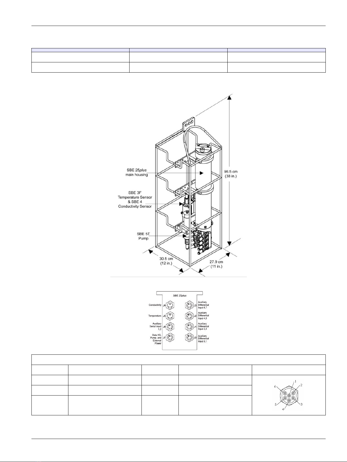
2.1.1 Dimensions
2.1.2 Connectors and cables
J3 auxiliary differential input 6, 7
Contact Function Contact Function MCBH6MP
1 Common 4 Voltage 7 signal
2 Voltage 6 signal 5 Voltage 7 common
3 Voltage 6 common 6 Auxiliary power out
5

J2 auxiliary differential input 4, 5
Contact Function Contact Function MCBH6MP
1 Common 4 Voltage 5 signal
2 Voltage 4 signal 5 Voltage 5 common
3 Voltage 4 common 6 Auxiliary power out
J1 auxiliary differential input 2, 3
Contact Function Contact Function MCBH6MP
1 Common 4 Voltage 3 signal
2 Voltage 2 signal 5 Voltage 3 common
3 Voltage 2 common 6 Auxiliary power out
J0 auxiliary differential input 0, 1
Contact Function Contact Function MCBH6MP
1 Common 4 Voltage 1 signal
2 Voltage 0 signal 5 Voltage 1 common
3 Voltage 0 common 6 Auxiliary power out
Connector Contact Function MCBH3MP
J4 Conductivity 1 Common
2 Conductivity frequency
3 Auxiliary power out
Connector Contact Function MCBH3MP
J5 Temperature 1 Common
2 Temperature frequency
3 Auxiliary power out
J6 auxiliary serial input 1, 2
Contact Function Contact Function MCBH6MP
Specifications
6

1 Common 4 Serial 2 data RX
2 Serial 1 data RX 5 Serial 2 data TX
3 Serial 1 data TX 6 Auxiliary power out
J7 data I/O, pump, external power
Contact Function Contact Function MCBH6MP
1 Common 4 Pump power common
2 RS232 data RX 5 Pump power
3 RS232 data TX 6 Auxiliary power in,
14–20 VDC
Figure 1 Y cable
Figure 2 Data I/O cable
Figure 3 SBE 4 to CTD cable
Notes:
• The Y cable from J7 connects to the pump and a data I/O power cable, so the system
can connect to a PC for setup and to transmit data, and to externally power the
25plus.
•Auxiliary sensors that draw more than 1 amp, even momentarily, must be
connected to J3 or J6. Refer to High current-draw sensor integration
on page 57 for details.
Specifications
7

2.2 Communications
Memory 2 GB
Communication interface RS232
Data collection rate 16 Hz
2.3 Electrical
Input from external power supply 14–20 VDC
Current draw, operation (no auxiliary sensors or pump) 95 mA
Current draw, pump 150 mA
Current draw, communications 70 mA
Current draw, low power (powered by internal batteries) 70 µA
Current draw, low power (powered by external batteries) 175 µA
2.4 Analytical
Parameter Range Accuracy Resolution
Conductivity 0–70 mS/cm ±0.003 mS/cm 0.0001 mS/cm
Temperature -5–35 °C ±0.002 °C (-5–35 °C) 0.0001 °C
Pressure various to 7000 m ±0.1% full scale range 0.002% full scale range
Specifications
8

Section 3 Overview
The battery-powered 25plus measures temperature, conductivity, and pressure and
supports up to 8 voltage-output sensors and 2 RS232 sensors. Components include:
• SBE 3F temperature sensor
• SBE 4C conductivity sensor
• SBE 5 pump
• Eight 16-bit A/D channels for auxiliary voltage output sensors for dissolved oxygen,
pH, fluorescence, PAR, light transmission, turbidity, and other measurements
• Two channels for auxiliary serial output sensors
• Stainless steel cage
• Optional: strain-gauge pressure sensor in eight depth ranges.
The 25plus has a 16 Hz scan rate for high spatial resolution and can operate for up to
55 hours (without auxiliary sensors). It records and stores data that is transmitted through
RS232 or USB to a PC. Data can also be transmitted in real-time from 0.5 to 8 Hz.
Data storage
Example 1 2GB memory, no auxiliary sensors. T, C, and P = 10 bytes/sample
storage: 2,000,000,000 ÷ 10 = 200,000,000 samples
Example 2 2GB memory, 4 auxiliary sensors. T, C, and P = 10 bytes/sample
External voltages = 2 bytes per sample × 4 sensors = 8 bytes per sample
storage: 2,000,000,000 ÷ (10 + 8) ~ 111,111,111 samples
The 25plus can be integrated with an SBE 32 Carousel Water Sampler or an SBE
55 ECO Water Sampler. It can also be used with an SBE 36 Deck Unit and Power/Data
Interface Module (PDIM) or SBE 33 Deck Unit and water sampler for real-time operation
with cable lengths up to 10,000 m.
3.1 Integration with other equipment for real-time data collection
The 25plus can be used with any of the equipment listed below:
• SBE 32 Carousel Water Sampler (12, 24, or 36 bottles) and SBE 33 Carousel Deck
Unit
• SBE 36 CTD Deck Unit and PDIM
• SBE 55 ECO Water Sampler (3 or 6 bottles) and SBE 33 Carousel Deck Unit.
All of these supply a minimum of 15 VDC to the 25plus, and supply sufficient power for
auxiliary sensors. The bottles on the SBE 32 and SBE 55 and be closed at any depth and
will not have an effect on data collection.
9
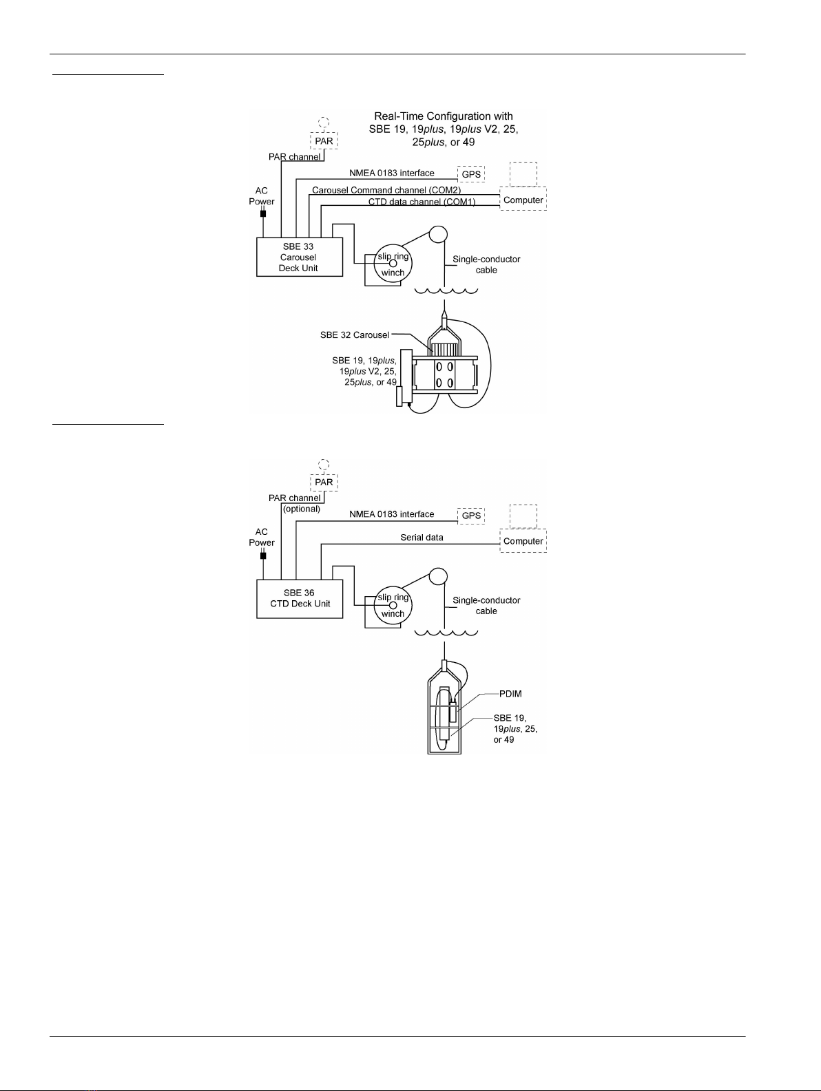
Figure 4 SBE 32
Figure 5 SBE 36
Overview
10
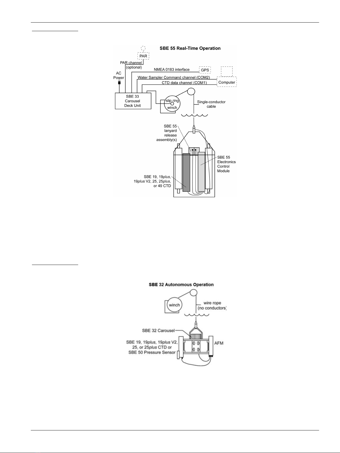
Figure 6 SBE 55
3.2 Integration with other equipment for autonomous operation
The 25plus can be used with the SBE 32 with an Auto Fire Module (AFM) or an SBE 55.
The AFM supplies voltage, logic, and control of the SBE 32. The AFM monitors the
pressure data from the 25plus in real-time and closes the water sample bottles at user-
specified depths or when the system is stopped for a specified period of time. The bottle
number, the firing confirmation and five scans of CTD data are stored the AFM memory
for each bottle. The SBE 55 operates almost the same as the AFM.
Figure 7 SBE 32
Overview
11

Figure 8 SBE 55
Overview
12

Section 4 Set up sensor and verify operation
Set up the hardware and install the software to make sure that the 25plus functions
correctly before deployment. Make sure that the sensor is connected to a power supply
and PC through the serial connector on the supplied cable. Most PCs no longer have
serial ports, and a serial-to-USB adapter is necessary. Make sure that the USB driver
software is installed on the PC so that there is communication between the sensor and
the PC.
1. Install the Seasoft V2 software from the manufacturer-supplied CD or the
manufacturer's website.
2. Remove the dummy plug from Y-cable to the sensor at connector J7.
3. Connect the I/O cable to the sensor and to the PC and a power supply (14–20 VDC).
4. Supply power to the 25plus.
5. Double-click on SeatermV2.exe to start the launcher.
a. Install SeatermV2, the terminal program launcher
b. Install Seaterm AF, the terminal program for autonomous water sampler setup
c. Install Seasave V7, real-time data collection
d. Install SBE Data Processing, the software to process collected data.
If this is the first time the software is opened, a Serial Port Configuration window
opens. The software automatically connects at the default baud rate of 9600 but will
try others if necessary. The software automatically looks for the serial port number of
the connected sensor.
6. At the Instruments menu item, select the software version associated with the
communication protocol of the sensor.
7. Push OK to close this window. The main window opens. The area on the left shows
available commands. The large area on the right shows commands and the
responses from the sensor to those commands.
8. To take a sample, enter TS. The display shows all 8 voltage channels, and will not
show serial sensor data.
0000000000040007000500000005000300060006007599B0008053B34597F32B45E
135FE
with 72 Hex characters displayed:
(iiiiiiiivvvvvvvvvvvvvvvvvvvvvvvvvvvvvvvv00pppppp00ppppppcccccccctttttttt)
iiiiiiii = diagnostic information
vvvv = external voltage sensor 7 voltage
vvvv = external voltage sensor 6 voltage
vvvv = external voltage sensor 5 voltage
vvvv = external voltage sensor 4 voltage
vvvv = external voltage sensor 3 voltage
vvvv = external voltage sensor 2 voltage
vvvv = external voltage sensor 1 voltage
vvvv = external voltage sensor 0 voltage
00pppppp = pressure temperature counts
00pppppp = pressure sensor counts
cccccccc = conductivity (Hz)
tttttttt = temperature (Hz)
9. To put the 25plus in a low power mode, enter QS, then push Enter.
The 25plus is ready to configure and deploy.
13

4.1 Software menu items
Note that the sensor will "time out" if it does not receive a command for two minutes. To
start the sensor again, select Connect in the software Communications menu or push
Enter.
Menu item Description
File Load command file opens the selected .xml command file in the "Send Commands" area.
Unload command file closes the file and removes the commands from the "Send Commands" area.
Exit closes the program.
Communications Connect connects to the COM port. Disconnect disconnects from the COM port.
Configure establishes COM port and baud rates.
Disconnect and reconnect turns communications off then on. Useful if a sensor is non-responsive.
Command Abort stops the sensor. (The Esc key is equivalent.)
Send 5-second break is used with Serial Line Sync Mode.
Send stop command stops sensor operation.
Set local time/Set UTC time sets the clock in the sensor. (This is disabled if the baud rate is set at
115200 because the software cannot set the time at that rate.)
Capture Capture sensor responses to save real-time data or for diagnostics. Select Capture again to turn it off.
Capture status shows in the "Status" bar.
Upload Upload data from the sensor to a PC. Data is in an .xml format and is automatically converted to a .hex
and .xmlcon file for the Data Conversion software module.
Tools Diagnostics log saves diagnostic data.
Use Convert .xml data file to manually convert data if the automatic Upload does not convert the data.
Send script sends the same setup information to a number of MicroCAT sensors.
Options Select (default) or deselect the option to Prompt to launch data conversion after data upload.
4.2 Communication troubleshooting
Do the steps below if the sensor does not respond to GetHD andGetHD to troubleshoot
the problem.
1. In the Communications menu, select Configure. In the Configure Communications
window, select the COM port and baud rate for communication. The manufacturer-set
baud rate is on the Configuration page that ships with the sensor.
2. Push OK.
3. In the Communications menu, select Connect.
• If Connect is not available, select Disconnect and reconnect. The software will try
to connect at the specified baud rate, but will try all other available baud rates to
try to connect.
4. If there is still no communication, check the cable and connections with the sensor
and the PC.
5. If there is still no communication, do step 1 with a different COM port or baud rate and
try to connect again.
Set up sensor and verify operation
14

4.3 Prepare the 25plus for vertical or horizontal deployment
The Sealogger is typically deployed in a vertical
position. The manufacturer configures the pump
and plumbing at the time of purchase, but the
system can be changed as necessary.
Make sure to attach the pump and plumbing
correctly so that no air enters the pump. It
will not operate correctly if it traps air.
4.3.1 Vertical deployment
• The manufacturer-supplied tubing is Tygon®, with an inside diameter (ID) of 13 mm
and an outside diameter (OD) of 19 mm (½ x ¾ in).
• Make sure the pump exhaust is as far away as possible from the intake so that water
from the exhaust is not pulled into the temperature sensor intake: the pump make the
exhaust water warmer, which can result in incorrect temperature data.
• Attach a 13 mm section of 9.5 mm ID Tygon tubing at the DO sensor intake. Put a
13 mm ID section over the smaller tubing to make a tight seal.
• Make sure to attach the DO sensor intake as shown above, so that the exhaust has
no effect on operation.
• If the system does not have a SBE 43 DO sensor, connect the tubing from the
conductivity cell directly to the Y fitting.
Set up sensor and verify operation
15

4.3.2 Horizontal deployment
• The manufacturer-supplied tubing is Tygon®, with an inside diameter (ID) of 13 mm
and an outside diameter (OD) of 19 mm (½ x ¾ in).
• Put the DO sensor intake above the conductivity sensor exhaust.
• Make sure the pump is attached with the exhaust "corner" up.
• Attach a 13 mm section of 9.5 mm ID Tygon tubing at the DO sensor intake. Put a
13 mm ID section over the smaller tubing to make a tight seal.
• If the system does not have a SBE 43 DO sensor, connect the tubing from the
conductivity cell directly to the Y fitting.
4.4 External power and cable length
The sensor can use an external power source that supplies 14–20 VDC through the Y-
cable that is connected to the data I/O, pump, and external power bulkhead connector
(J7). If external power of more than 14 V is supplied, the 25plus uses the external power,
even if the main battery voltage is higher. The 25plus can also operate from the external
power supply without the internal battery pack installed.
On a ship, cables longer than 3 meters should be installed inside a grounded metal
conduit by a qualified electrician.
Make sure to calculate IR loss for real-time data collection with external power:
1. The communication IR loss should be 1 V or less, or the sensor will transmit data that
does not meet the RS232 communication standard.
2. Supply enough power so that sufficient power is available to the sensor after IR loss
is calculated.
Calculate communication IR loss
Vlimit = 1 V = IRlimit
Maximum cable length = Rlimit ÷ wire resistance/foot.
I = required communication current.
Set up sensor and verify operation
16

Example, no auxiliary sensors:
What is the maximum cable length needed to supply power to the 25plus with 20 gauge wire, with data transmitted in real-
time?
Current draw = 95 mA (data collection) + 150 mA (pump) + 70 mA (communications) = 315 mA
Rlimit = Vlimit ÷ I = 1 V ÷ 0.315 A = 3.2 ohms
Maximum cable length = 3.2 ohms ÷ 0.0107 ohms/ft = 299 ft = 91 m
Supply sufficient power
Supply enough power so that sufficient voltage is available to operate the 25plus. The
table below shows the maximum 2-way resistance for various input supplies.
Power supply input Rlimit = maximum 2-way resistance
3.0 A at 14 V input, 5T or 5P pump 2 ohms
1.5 A at 19 V input, 5T or 5P pump 7 ohms
Example
What is the maximum cable length to supply power to the 25plus with 20 gauge wire, a 12 V power supply, and no internal
batteries?
Maximum cable length = Rlimit ÷ 2 ohms × wire resistance per foot = 2 × 0.0107 ohms/ft = 93 ft, or 28 m.
28 m < 91 m, so the IR drop in power is the factor that controls cable length. Use a higher voltage power supply or another
wire gauge to increase the cable length.
Table 1 Common wire resistance
Gauge Ohms/ft
12 0.0016
14 0.0025
16 0.0040
18 0.0064
20 0.0081
22 0.0107
24 0.0162
26 0.0410
28 0.0653
4.5 Battery pack
WARNING
Explosion hazard. If the batteries are not installed correctly, explosive gases can be
released. Make sure that the batteries are of the same approved chemical type and are
inserted in the correct orientation.
WARNING
If the user thinks that a sensor has water in the pressure housing: Disconnect the sensor from any
power supply. Put on safety glasses and make sure that the sensor is pointed away from the body
and other people. In a well ventilated area, use the purge port (if the sensor is so equipped), or
very SLOWLY loosen the bulkhead connector to let the pressure release.
Set up sensor and verify operation
17

WARNING
If the user thinks that the alkaline batteries have leaks, pressure may have built up inside of the
pressure housing. Follow ESD protocols to release internal pressure. Put on safety glasses and
protective gloves and make sure that the sensor is pointed away from the body and other people.
In a well ventilated very SLOWLY loosen the bulkhead connector to release the pressure. Keep
away from heat, sparks, flame, and other sources of ignition. Do not smoke.
WARNING
This product can expose the user to chemicals with silica, crystalline (airborne particles of
respirable size), which is known to the State of California to cause cancer and birth defects or
other reproductive harm. For more information, go to www.P65Warnings.ca.gov.
CAUTION
The pressure housing contains Electrostatic Discharge (ESD) sensitive parts and assemblies that
are susceptible to damage from ESD. Follow ESD protocols.
NOTICE
To SLOWLY remove the bulkhead connector: loosen one bulkhead connector by 1 turn to open
the O-ring seal under the connector. If there is internal pressure, water may leak out or you may
hear a hiss. Let the pressure bleed off slowly. Then it will be safe to remove the end flange.
ESD Protocol
• Put on protective eye wear before you open the pressure housing.
• Any electrostatic charge on the body of the human operator must be released before the pressure housing is
opened: put a hand on a grounded surface, or better, wear a grounded antistatic wrist strap.
• At a minimum, wear short-sleeved antistatic clothing, such as cotton, or better, wear an antistatic smock for
this service activity. Do not wear a sweater, fleece or polyester-based clothing.
• At a minimum, use a workstation with a wood or metal tabletop, or better, a tabletop that dissipates static. Do
not use a workstation with a synthetic or polymeric-based tabletop.
The Sealogger uses 12 D-cell alkaline batteries for the main power supply (Duracell®
MN1300, LR20).
Remove the batteries if the 25plus will be stored for a long period. Store batteries at a
temperature between 5 °C and 30 °C.
Refer to the section on Replace batteries on page 34 for details about how to replace
batteries. The batteries have a nominal capacity of 18.6 Ah. The manufacturer recommends a
conservative value to calculate battery life:
• 14 Ah when the current draw is less than 500 mA for auxiliary sensors.
• 5 Ah when the current draw is more than 500 mA for auxiliary sensors.
Examples of battery life calculations:
No auxiliary sensors Data collection current draw (T, C, P) = 95 mA = 0.095 A
Pump current draw = 150 mA = 0.15 A
Maximum data collection time ~ 14 Ah ÷ (0.095 + 0.15) ~ 55 hours
Set up sensor and verify operation
18
Table of contents
Other Sea-Bird Scientific Data Logger manuals


![Lambrecht Ser[LOG] Operator's manual](/data/manuals/17/2/172t1/sources/lambrecht-ser-log-data-loggers-manual.jpg "Lambrecht Ser[LOG] Operator's manual")


