Sea-Bird Scientific SBE 37-SM User manual
Copyright 2017 Sea-Bird Scientific. All rights reserved.
Release Date
Version
Firmware
Software
10/18/2018
041
5.1.1 & later
Seaterm V2 2.6.3 & later
SBE Data Processing 7.26.7 & later
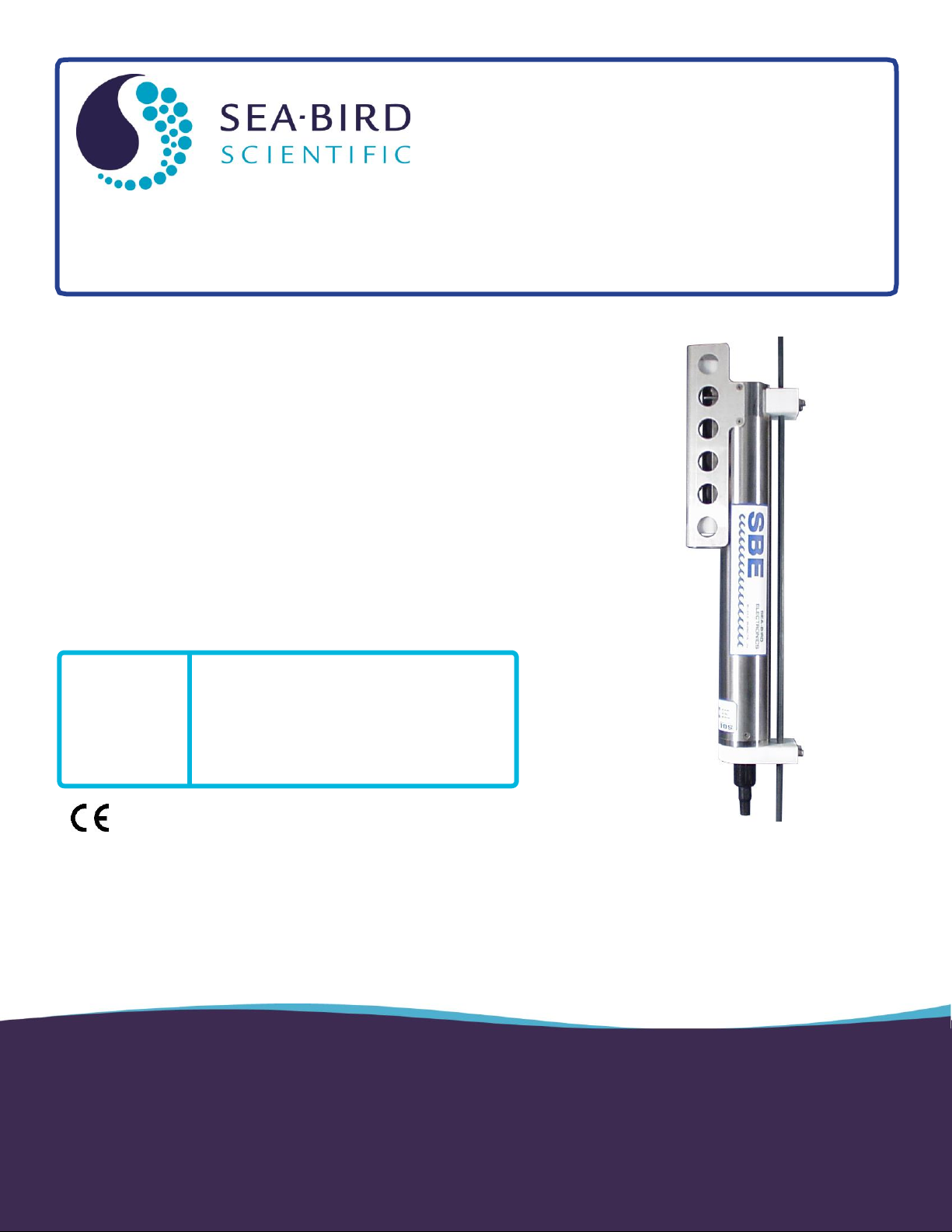
SBE 37-SM MicroCAT C-T-(P) Recorder
Conductivity and Temperature (pressure optional) Recorder with RS-232 Interface
Product Manual

2
Limited Liability Statement
Extreme care should be exercised when using or servicing this equipment. It should be used or serviced
only by personnel with knowledge of and training in the use and maintenance of oceanographic
electronic equipment.
SEA-BIRD ELECTRONICS, INC. disclaims all product liability risks arising from the use or servicing
of this system. SEA-BIRD ELECTRONICS, INC. has no way of controlling the use of this equipment
or of choosing the personnel to operate it, and therefore cannot take steps to comply with laws
pertaining to product liability, including laws which impose a duty to warn the user of any dangers
involved in operating this equipment. Therefore, acceptance of this system by the customer shall be
conclusively deemed to include a covenant by the customer to defend, indemnify, and hold SEA-BIRD
ELECTRONICS, INC. harmless from all product liability claims arising from the use or servicing of
this system.
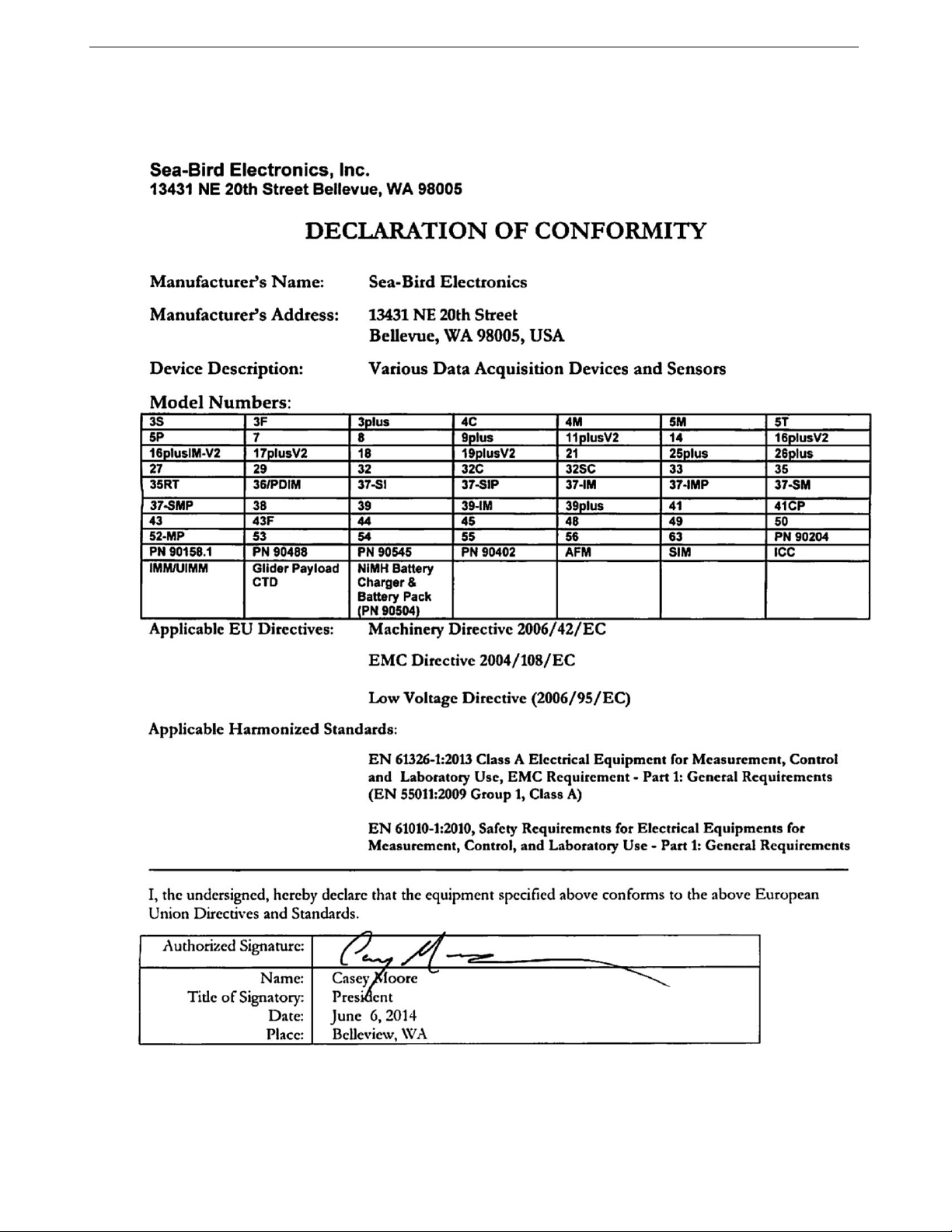
Manual revision 041 Declaration of Conformity SBE 37-SM RS-232
3
Declaration of Conformity

Manual revision 041 Table of Contents SBE 37-SM RS-232
4
Table of Contents
Limited Liability Statement................................................................ 2
Declaration of Conformity .................................................................. 3
Table of Contents................................................................................. 4
Section 1: Introduction........................................................................ 6
About this Manual .............................................................................................6
Quick Start.........................................................................................................6
Unpacking MicroCAT .......................................................................................7
Shipping Precautions .........................................................................................8
Section 2: Description of MicroCAT.................................................. 9
System Description............................................................................................9
Specifications...................................................................................................11
Dimensions and End Cap Connector ...............................................................12
Cables and Wiring ...........................................................................................13
Sample Timing.................................................................................................14
Battery Pack Endurance...................................................................................14
External Power.................................................................................................15
Cable Length and External Power ............................................................15
Section 3: Preparing MicroCAT for Deployment.......................... 16
Battery Pack Installation..................................................................................16
Description of Cells and Battery Pack......................................................16
Installing Cells and Battery Pack..............................................................16
Software Installation........................................................................................18
Power and Communications Test ....................................................................18
Test Setup .................................................................................................18
Test ...........................................................................................................19
Section 4: Deploying and Operating MicroCAT............................ 24
Sampling Modes ..............................................................................................24
Polled Sampling........................................................................................25
Autonomous Sampling (Logging commands)..........................................26
Serial Line Synchronization (Serial Line Sync) .......................................27
Real-Time Data Acquisition ............................................................................28
Timeout Description ........................................................................................28
Command Descriptions....................................................................................29
Data Formats....................................................................................................45
Setup for Deployment......................................................................................49
Deployment......................................................................................................50
Recovery..........................................................................................................51
Uploading and Processing Data.......................................................................52
Editing Raw Data File......................................................................................59
Section 5: Routine Maintenance and Calibration.......................... 60
Corrosion Precautions......................................................................................60
Connector Mating and Maintenance................................................................60
Conductivity Cell Maintenance .......................................................................61
Pressure Sensor (optional) Maintenance..........................................................62
O-Ring Maintenance........................................................................................62
Handling Instructions for Plastic ShallowCAT ................................................63
Replacing AA Cells .........................................................................................63
Replacing Anti-Foulant Devices (SBE 37-SI, SM, IM)...................................65
Sensor Calibration............................................................................................66
Conductivity Sensor Calibration...............................................................66
Temperature Sensor Calibration...............................................................66

Manual revision 041 Table of Contents SBE 37-SM RS-232
5
Pressure Sensor (optional) Calibration .....................................................67
Section 6: Troubleshooting................................................................ 68
Problem 1: Unable to Communicate with MicroCAT .....................................68
Problem 2: No Data Recorded .........................................................................68
Problem 3: Unreasonable T, C, or P Data........................................................68
Problem 4: Salinity Spikes...............................................................................69
Glossary .............................................................................................. 70
Appendix I: Functional Description................................................. 72
Sensors.............................................................................................................72
Sensor Interface ...............................................................................................72
Real-Time Clock..............................................................................................72
Appendix II: Electronics Disassembly/Reassembly........................ 73
Disassembly.....................................................................................................73
Reassembly......................................................................................................73
Appendix III: Command Summary................................................. 74
Appendix IV: AF24173 Anti-Foulant Device .................................. 77
Appendix V: Replacement Parts ...................................................... 81
Appendix VI: Manual Revision History .......................................... 83

Manual revision 041 Section 1: Introduction SBE 37-SM RS-232
6
Section 1: Introduction
This section includes a Quick Start procedure, photos of a typical MicroCAT
shipment, and battery shipping precautions.
About this Manual
This manual is to be used with the SBE 37-SM MicroCAT Conductivity and
Temperature Recorder (pressure optional) with RS-232 interface. It is
organized to guide the user from installation through operation and data
collection. We’ve included detailed specifications, command descriptions,
maintenance and calibration information, and helpful notes throughout
the manual.
Sea-Bird welcomes suggestions for new features and enhancements of our
products and/or documentation. Please contact us with any comments or
Monday through Friday, 0800 to 1700 Pacific Standard Time (1600 to 0100
Universal Time) in winter and 0800 to 1700 Pacific Daylight Time (1500 to
0000 Universal Time) the rest of the year.
Quick Start
Follow these steps to get a Quick Start using the MicroCAT.
The manual provides step-by-step details for performing each task:
1. Install AA lithium cells and test power and communications (Section 3:
Preparing MicroCAT for Deployment).
2. Deploy the MicroCAT (Section 4: Deploying and Operating MicroCAT):
A. Install new AA lithium cells if necessary.
B. Ensure all data has been uploaded, and then send InitLogging to
make entire memory available for recording if desired.
C. Set date and time, and establish setup and logging parameters.
D. Check status (DS) and calibration coefficients (DC) to verify setup.
E. If you will be sampling autonomously, use one of the following
sequences to start logging:
StartNow to start logging now, sampling every
SampleInterval= seconds.
StartDateTime= and StartLater to start logging at specified
date and time, sampling every SampleInterval= seconds.
F. Remove protective plugs from anti-foulant device cups, and verify
AF24173 Anti-Foulant Devices are installed. Leave protective plugs
off for deployment.
G. Install dummy plug or cable connector, and locking sleeve.
H. Deploy MicroCAT, using Sea-Bird or customer-supplied hardware.
I. Upload data from memory.
Manual revision 041 Section 1: Introduction SBE 37-SM RS-232
7
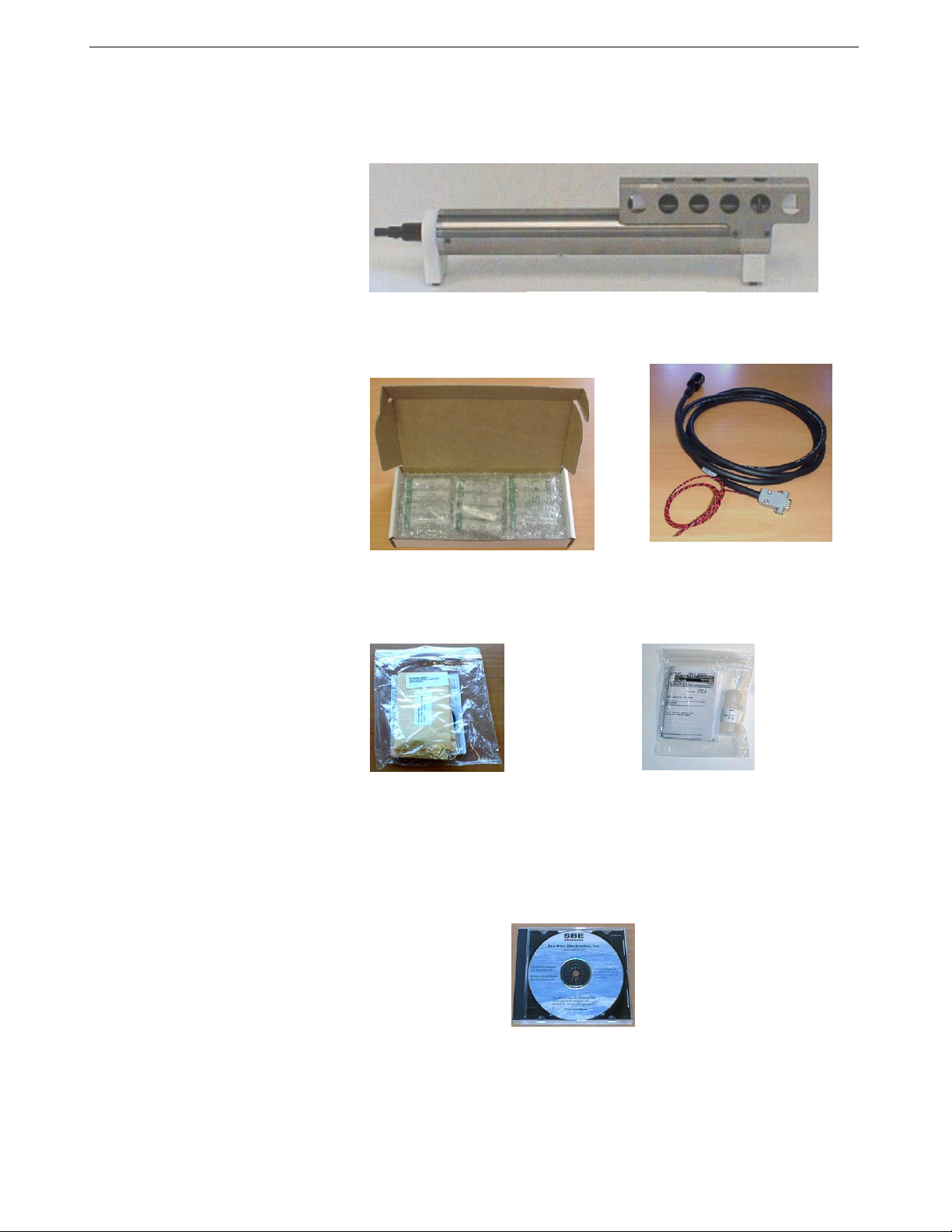
Unpacking MicroCAT
Shown below is a typical MicroCAT shipment.
Spare hardware
and o-ring kit
SBE 37-SM MicroCAT
Cell cleaning solution
(Triton-X)
Software, and Electronic Copies of
Software Manuals and User Manual
I/O cable
12 AA lithium cells

Manual revision 041 Section 1: Introduction SBE 37-SM RS-232
8
Shipping Precautions
For its main power supply, the MicroCAT uses twelve 3.6-volt AA lithium
cells (Saft LS14500). The MicroCAT was shipped from the factory with the
batteries packaged separately within the shipping box (not inside MicroCAT).
If the shipment is not packaged as described above, or does not meet the requirements below, the
shipment is considered Dangerous/Hazardous Goods, and must be shipped according to those rules.
1-5 MicroCATs
and associated
cells,
but no spares
1-5 MicroCATs and
associated cells,
plus up to 2 spare
cell sets/MicroCAT
Spares
(without MicroCATs) –
Note new rules as of
January 1, 2013
UN #
UN3091
UN3091
Must be shipped as
Class 9 Dangerous Goods.
If re-shipping spares, you must have your
own Dangerous Goods program.
Packing Instruction (PI) #
969
969
Passenger Aircraft
Yes
No
Cargo Aircraft
Yes
Yes
Labeling Requirement
1 **
1, 2 **
Airway Bill (AWB)
Requirement
Yes *
Yes *
* AWB must contain following information in Nature and Quantity of Goods Box: “Lithium Metal Batteries”, “Not Restricted”, “PI #”
** Labels are defined below:
Install the battery pack assembly in the MicroCAT for testing (see Battery
Pack Installation in Section 3). If you will re-ship the MicroCAT after
testing:
1. Remove the battery pack assembly from the MicroCAT.
2. Remove the cells from the battery pack assembly.
3. Pack the cells properly for shipment, apply appropriate labels, and prepare
appropriate shipping documentation.
BATTERY PACKAGING
Cells are packed in heat-sealed plastic, and
then placed in bubble-wrap outer sleeve
and strong packaging for shipment.
DISCLAIMER / WARNING:
The shipping information provided in is a general overview of lithium battery shipping requirements; it does not provide
complete shipping information. The information is provided as a courtesy, to be used as a guideline to assist properly trained
shippers. These materials do not alter, satisfy, or influence any federal or state requirements. These materials are subject to
change due to changes in government regulations. Sea-Bird accepts no liability for loss or damage resulting from changes,
errors, omissions, or misinterpretations of these materials. See the current edition of the IATA Dangerous Good
Regulations for complete information on packaging, labeling, and shipping document requirements.
Note:
Remove the cells before returning the
MicroCAT to Sea-Bird. Do not return
used cells when shipping the
MicroCAT for calibration or repair. All
setup information is preserved when
the cells are removed.
2
1 –Shipper must provide an
emergency phone number
xxx.xxxx.xxxx
WARNING!
Do not ship
assembled
battery pack.
Assembled
battery
pack

Manual revision 041 Section 2: Description of MicroCAT SBE 37-SM RS-232
9
Section 2: Description of MicroCAT
This section describes the functions and features of the SBE 37-SM
MicroCAT, including specifications, dimensions, end cap connectors, sample
timing, battery pack endurance, and external power.
System Description
The SBE 37-SM MicroCAT is a high-accuracy conductivity and temperature
recorder (pressure optional) with internal battery pack and non-volatile
memory, and an RS-232 serial interface. Designed for moorings and other
long-duration, fixed-site deployments, MicroCATs have non-corroding
housings. The MicroCAT is rated for operation to 350 meters (plastic
ShallowCAT housing) or 7000 meters (titanium housing), or pressure sensor
full-scale range.
Communication with the MicroCAT is over an internal, 3-wire, RS-232C
link. Over 50 different commands can be sent to the MicroCAT to provide
status display, data acquisition setup, data retrieval, and diagnostic tests.
User-selectable operating modes include:
Autonomous sampling –At pre-programmed intervals, the MicroCAT
wakes up, samples, stores data in its FLASH memory, and goes to sleep.
If desired, real-time data can also be transmitted.
Polled sampling –On command, the MicroCAT takes one sample and
transmits the data. Polled sampling is useful for integrating the MicroCAT
with satellite, radio, or wire telemetry equipment.
Serial line sync –In response to a pulse on the serial line, the MicroCAT
wakes up, samples, stores the data in its FLASH memory, and goes to
sleep. If desired, real-time data can also be transmitted. Serial line sync
provides an easy method for synchronizing MicroCAT sampling with
other instruments such as Acoustic Doppler Current Profilers (ADCPs) or
current meters, without drawing on their battery or memory resources.
The MicroCAT can be deployed in two ways:
Cable installed and connected to RS-232 or USB port on computer –
The MicroCAT can be remotely controlled, allowing for polled sampling
or serial line sync, or for periodic requests of data from the memory. If
desired, data can be periodically uploaded while the MicroCAT remains
deployed. Additionally, the MicroCAT can be externally powered.
Dummy plug installed –The MicroCAT cannot be remotely controlled.
Autonomous sampling is programmed before deployment, and data is
uploaded after recovery.
Calibration coefficients stored in EEPROM allow the MicroCAT to transmit
data in engineering units. The MicroCAT retains the temperature and
conductivity sensors used in the Seacat and Seacat plus family. The
MicroCAT’s aged and pressure-protected thermistor has a long history of
exceptional accuracy and stability (typical drift is less than 0.002 °C per year).
Electrical isolation of the conductivity electronics eliminates any possibility of
ground-loop noise.
Titanium
housing
Plastic
ShalowCAT
housing

Manual revision 041 Section 2: Description of MicroCAT SBE 37-SM RS-232
10
The MicroCAT’s internal-field conductivity cell is immune to proximity errors
and unaffected by external fouling. A plastic cup with threaded cover at each
end of the cell retains the expendable AF24173 Anti-Foulant Device.
The MicroCAT’s optional strain-gauge pressure sensor is available in the
following pressure ranges: 20, 100, 350, 600, 1000, 2000, 3500, and
7000 meters. Compensation of the temperature influence on pressure offset
and scale is performed by the MicroCAT’s CPU.
Future upgrades and enhancements to the MicroCAT firmware can be easily
installed in the field through a computer serial port and the bulkhead connector
on the MicroCAT, without the need to return the MicroCAT to Sea-Bird.
The MicroCAT is supplied with a powerful Windows software package,
Seasoft©V2, which includes:
Deployment Endurance Calculator–program for determining
deployment length based on user-input deployment scheme, instrument
power requirements, and battery capacity.
SeatermV2 –terminal program for easy communication and data
retrieval. SeatermV2 is a launcher, and launches the appropriate terminal
program for the selected instrument (Seaterm232 for RS-232 instruments
such as this MicroCAT).
SBE Data Processing - program for calculation and plotting of
conductivity, temperature, pressure (optional), and derived variables such
as salinity, sound velocity, depth, density, etc.
Notes:
Help files provide detailed
information on the software.
A separate software manual on
CD-ROM contains detailed
information on the setup and
use of SBE Data Processing.
Sea-Bird supplies the current
version of our software when you
purchase an instrument. As software
revisions occur, we post the revised
software on our website. See our
website for the latest software
version number, a description of the
software changes, and instructions
for downloading the software.
Manual revision 041 Section 2: Description of MicroCAT SBE 37-SM RS-232
11
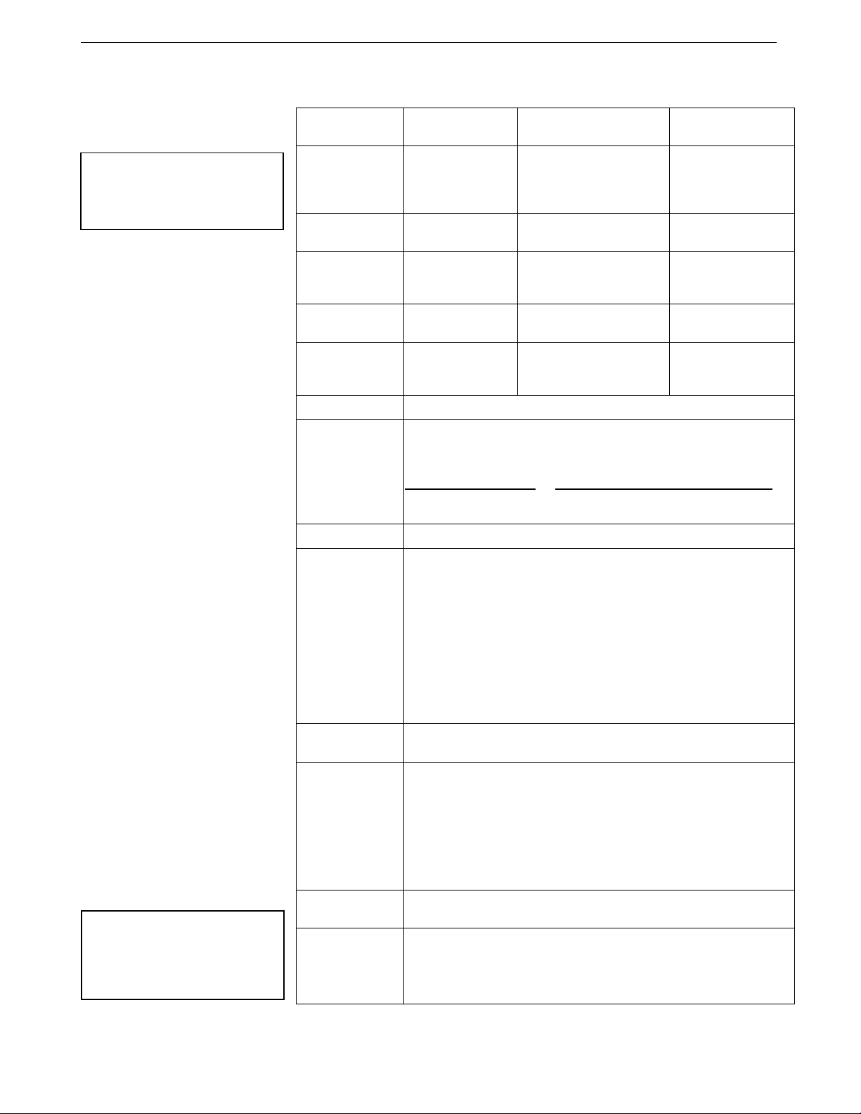
Specifications
Temperature (°C)
Conductivity
(S/m)
Optional
Pressure
Measurement
Range
-5 to +45
0 to 7
(0 to 70 mS/cm)
0 to full scale range:
20 / 100 / 350 / 600 /
1000 / 2000 / 3500 /
7000 meters
Initial
Accuracy
± 0.002 (-5 to 35 °C);
± 0.01 (35 to 45 °C)
± 0.0003
(0.003 mS/cm)
± 0.1% of
full scale range
Typical
Stability
0.0002
per month
0.0003
(0.003 mS/cm)
per month
0.05% of
full scale range
per year
Resolution
0.0001
0.00001
(0.0001 mS/cm)
0.002% of
full scale range
Sensor
Calibration
+1 to +32
0 to 6; physical calibration
over range 2.6 to 6 S/m, plus
zero conductivity (air)
Ambient pressure to
full scale range in
5 steps
Memory
8 Mbyte non-volatile FLASH memory
Data
Storage
Conductivity & temperature: 6 bytes per sample (3 bytes each)
Time: 4 bytes per sample.
Pressure (optional): 5 bytes per sample.
Recorded Parameters Memory Space (number of samples)
C, T, and time 800,000
C, T, P, and time 533,000
Real-Time Clock
32,768 Hz TCXO accurate to 1 minute/year.
Battery Pack
Nominal 7.8 Amp-hour pack consisting of 12 AA Saft LS 14500
lithium cells (3.6 V and 2.45 Amp-hours each), with 3 strings of 4
cells. For battery pack endurance calculations, derated capacity of
257 KJoules (see Battery Pack Endurance for example calculation).
See Shipping Precautions in Section 1: Introduction.
Note: Saft cells can be purchased from Sea-Bird or other sources.
See Saft’s website for suppliers (www.saftbatteries.com).
Alternatively, substitute either of the following:
- Tadiran TL-4903, AA (3.6 V and 2.4 Amp-hours each)
(www.tadiran.com)
- Electrochem 3B0064/BCX85, AA (3.9 V and 2.0 Amp-hours each)
(www.electrochemsolutions.com)
External
Input Power
0.25 Amps at 9-24 VDC. To avoid draining internal battery pack, use
external voltage greater than 10 VDC. See External Power.
Power
Requirements
Quiescent current: 30 microAmps (0.0004 Watts).
Communication current: 4.3 milliAmps.
Acquisition current:
- 9.1 milliAmps if transmitting real-time data.
- 7.9 milliAmps if not transmitting real-time data.
Acquisition time: 1.9 –2.9 seconds per sample (depending on
sampling mode and inclusion of pressure sensor, see Sample
Timing).
Housing and
Depth Rating
Titanium housing, 7000 m (23,000 ft)
Plastic housing, 350 m (1150 ft)
Weight
(without pressure
sensor)
Titanium housing:
In air: 3.3 kg (7.2 lbs) In water: 2.0 kg (4.3 lbs)
Plastic housing:
In air: 2.4 kg (5.2 lbs) In water: 1.1 kg (2.3 lbs)
Note:
Pressure ranges are expressed
in meters of deployment depth
capability.
CAUTION:
See Section 5: Routine
Maintenance and Calibration for
handling instructions for the
plastic ShallowCAT housing.
Manual revision 041 Section 2: Description of MicroCAT SBE 37-SM RS-232
12
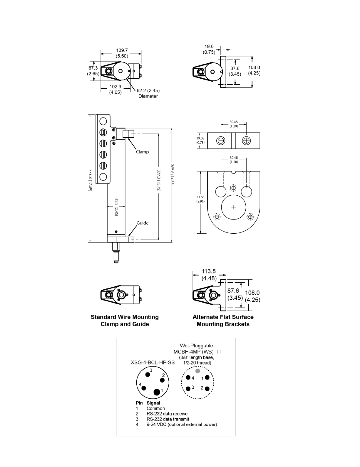
Dimensions and End Cap Connector
Dimensions in
millimeters (inches)
Manual revision 041 Section 2: Description of MicroCAT SBE 37-SM RS-232
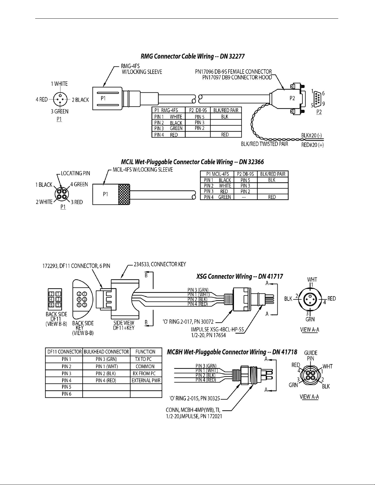
13
Cables and Wiring

Manual revision 041 Section 2: Description of MicroCAT SBE 37-SM RS-232
14
Sample Timing
Sample timing is dependent on several factors, including sampling mode and
whether the MicroCAT has an optional pressure sensor.
Autonomous Sampling (time between samples = SampleInterval)
Power on time for each sample while logging:
Without pressure: power-on time = 1.8 seconds
With pressure: power-on time = 2.4 seconds
Polled Sampling or Serial Line Sync Sampling
Time from end of take sample command to beginning of reply:
Without pressure: power-on time = 2.0 seconds
With pressure: power-on time = 2.6 seconds
Battery Pack Endurance
The battery pack (4 cells in series, 3 parallel strings) has a nominal capacity of
7.8 Amp-hours (2.6 Amp-hours * 3). For planning purposes, to account for the
MicroCAT’s current consumption patterns and for environmental conditions
affecting cell performance, Sea-Bird recommends using a conservative
value of 6.0 Amp-hours.
Acquisition current varies, depending on whether the MicroCAT is
transmitting real-time data: 15 mA if transmitting real-time data,
13 mA if not. Quiescent current is 30 microAmps (0.26 AH per year).
Acquisition time is shown above in Sample Timing. The time required for each
sample is dependent on the user-programmed sampling mode, and inclusion of
a pressure sensor in the MicroCAT. So, battery pack endurance is highly
dependent on the application. An example is shown below. You can use the
Deployment Endurance Calculator to determine the maximum deployment
length, instead of performing the calculations by hand.
Notes:
If the MicroCAT is logging data and
the battery pack voltage is less than
7.1 volts for five consecutive scans,
the MicroCAT halts logging.
Sea-Bird recommends using the
capacity value of 6.0 Amp-hours for
the Saft cells as well as the alternate
cell types (Tadiran TL-4903 and
Electrochem 3B0064/BCX85 AA).
This MicroCAT uses a battery pack
with a yellow cover plate. Older
SBE 37-SM MicroCATs use a
battery pack with a red cover plate;
those packs are wired differently,
and will not work properly in this
MicroCAT.
See Specifications above for data
storage limitations.
Example: A MicroCAT with pressure sensor is set up to sample autonomously every 10 minutes (6 samples/hour), and
is not transmitting real-time data. How long can it be deployed?
Sampling time (autonomous sampling, with pressure sensor) = 2.4 seconds
Sampling current consumption = 0.013 Amps * 2.4 seconds = 0.031 Amp-seconds/sample
In 1 hour, sampling current consumption = 6 * 0.031 Amp-seconds/sample = 0.19 Amp-seconds/hour
Quiescent current = 30 microAmps = 0.03 mA
In 1 hour, quiescent current consumption ≈ 0.03 mA * 3600 seconds/hour = 0.11 Amp-seconds/hour
Total current consumption / hour = 0.19 + 0.11 = 0.3 Amp-seconds/hour
Capacity = (8.8 Amp-hours * 3600 seconds/hr) / (0.3 Amp-seconds/hour) = 105,000 hours = 4400 days = 12 years!
However, Sea-Bird recommends that batteries should not be expected to last longer than 2 years in the field.
Number of samples = 105,000 hours * 6 samples/hour = 630,000 samples
Notes:
Acquisition time shown does not
include time to transmit real-time
data, which is dependent on baud
rate (BaudRate=) and number of
characters being transmitted
(defined by OutputFormat=,
OutputSal=, and OutputSV=).
Time stored and output with the data
is the time at the start of the
sample, after a small amount of time
for the MicroCAT to wake up and
prepare to sample. For example, if
the MicroCAT is programmed to
wake up and sample at 12:00:00,
the stored and displayed time will
indicate 12:00:01 or 12:00:02.
Manual revision 041 Section 2: Description of MicroCAT SBE 37-SM RS-232
15
External Power The MicroCAT can be powered from an external source that supplies
0.25 Amps at 9 –24 VDC. The internal lithium battery pack is diode-OR’d
with the external source, so power is drawn from whichever voltage source is
higher. The MicroCAT can also be operated from the external supply without
having the battery pack installed. Electrical isolation of conductivity prevents
ground loop noise contamination in the conductivity measurement.
Cable Length and External Power
There are two issues to consider if powering the MicroCAT externally:
Limiting the communication IR loss to 1 volt if transmitting real-time
data; higher IR loss will cause the instrument to transmit data that does
not meet the RS-232 communication standard.
Supplying enough power at the power source so that sufficient power is
available at the instrument after considering IR loss.
Each issue is discussed below.
Limiting Communication IR Loss to 1 Volt if Transmitting Real-Time Data
The limit to cable length is typically reached when the maximum
communication current times the power common wire resistance is more than
1 volt. Vlimit = 1 volt = IR limit
Maximum cable length = R limit / wire resistance per foot
where I = communication current required by MicroCAT (4.3 milliAmps;
see Specifications).
Supplying Enough Power to MicroCAT
Another consideration in determining maximum cable length is supplying
enough power at the power source so that sufficient voltage is available, after
IR loss in the cable (from the 0.25 Amp turn-on transient, two-way
resistance), to power the MicroCAT. The power requirement varies,
depending on whether any power is drawn from the battery pack:
Provide at least 16 volts, after IR loss, to prevent the MicroCAT from
drawing any power from the battery pack (if you do not want to draw
down the battery pack): V - IR > 10 volts
Provide at least 9 volts, after IR loss, if allowing the MicroCAT to draw
down the battery pack or if no battery pack is installed: V - IR > 9 volts
where I = MicroCAT turn-on transient (0.5 Amps; see Specifications).
Note:
Common wire resistances:
Gauge Resistance (ohms/foot)
12 0.0016
14 0.0025
16 0.0040
18 0.0064
19 0.0081
20 0.0107
22 0.0162
24 0.0257
26 0.0410
28 0.0653
Example 1 –For 20 gauge wire, what is maximum distance to transmit power to MicroCAT if transmitting real-time data?
For 5 milliAmp communications current, R limit = Vlimit / I = 1 volt / 0.0043 Amps = 200 ohms
For 20 gauge wire, resistance is 0.0107 ohms/foot.
Maximum cable length = 200 ohms / 0.0107 ohms/foot = 18691 feet = 6568 meters
Example 2 –Same as above, but there are 4 MicroCATs powered from the same power supply.
For 5 milliAmp communications current, R limit = Vlimit / I = 1 volt / (0.005 Amps * 4 MicroCATs) = 50 ohms
Maximum cable length = 50 ohms / 0.0107 ohms/foot = 4672 feet = 1424 meters (to MicroCAT furthest from power source)
Example 1 –For 20 gauge wire, what is maximum distance to transmit power to MicroCAT if using 12 volt power source
and deploying MicroCAT with no battery pack?
V - IR > 9 volts 12 volts - (0.25 Amps) * (0.0107 ohms/foot * 2 * cable length) > 9 volts
3 volts > (0.25 Amps) * (0.0107 ohms/foot * 2 * cable length) Cable length < 560 ft = 170 meters
Note that 85 m << 6626 m (maximum distance if transmitting real-time data), so IR drop in power is controlling factor for
this example. Using a higher voltage power supply or a different wire gauge would increase allowable cable length.
Example 2 –Same as above, but there are 4 MicroCATs powered from same power supply.
V - IR > 9 volts 12 volts - (0.25 Amps * 4 MicroCATs) * (0.0107 ohms/foot * 2 * cable length) > 9 volts
3 volts > (0.25 Amps * 4 MicroCATs) *(0.0107 ohms/foot * 2 * cable length)
Cable length < 140 ft = 42 meters (to MicroCAT furthest from power source)
Note:
See Real-Time Data Acquisition
in Section 4: Deploying and
Operating MicroCAT for baud rate
limitations on cable length if
transmitting real-time data.

Manual revision 041 Section 3: Preparing MicroCAT for Deployment SBE 37-SM RS-232
16
Section 3:
Preparing MicroCAT for Deployment
This section describes the pre-check procedure for preparing the MicroCAT
for deployment. Installation of the battery pack, installation of Sea-Bird
software, and testing power and communications are discussed.
Battery Pack Installation Description of Cells and Battery Pack
Sea-Bird supplies twelve 3.6-volt AA lithium cells, shipped with the
MicroCAT in a heat-sealed plastic bag placed in bubble wrap and a cardboard
box. The empty cell holder is installed inside the MicroCAT for shipment.
No soldering is required when assembling the battery pack.
Installing Cells and Battery Pack
1. Remove the I/O connector end cap:
A. Wipe the outside of the end cap and housing dry, being careful to
remove any water at the seam between them.
B. Remove the 2 cap screws on the sides of the housing. Do not remove
any other screws.
Note: Sea-Bird ships the MicroCAT with a 9/64-inch Allen wrench
for these screws.
C. Remove the I/O end cap by twisting the end cap counter clockwise;
the end cap will release from the housing. Pull the end cap out.
D. The end cap is electrically connected to the electronics with a Molex
connector. Holding the wire cluster near the connector, pull gently to
detach the female end of the connector from the pins.
E. Remove any water from the O-ring mating surfaces inside the
housing with a lint-free cloth or tissue.
F. Put the end cap aside, being careful to protect the O-rings from
damage or contamination.
WARNING!
Do not ship the MicroCAT with
battery pack installed.
See Shipping Precautions in
Section 1: Introduction.
AA cells in heat-sealed plastic, bubble-wrap
outer sleeve, and strong packaging.
CAUTION:
See Section 5: Routine Maintenance
and Calibration for handling
instructions for the plastic
ShallowCAT housing.
2 screws
securing
connector
end cap
(screws
shown
partially
removed)
Cable
mounting
guide
Molex connector
O-rings
Twist end cap
counter clockwise,
twisting cap screw
out of machined slot;
end cap releases
from housing.
Manual revision 041 Section 3: Preparing MicroCAT for Deployment SBE 37-SM RS-232
17
2. Remove the battery pack assembly from the housing:
A. Loosen the captured screw from the battery pack cover plate, using
the 7/64-inch Allen wrench included with the shipment.
B. Lift the battery pack assembly straight out of the housing, using
the handle.
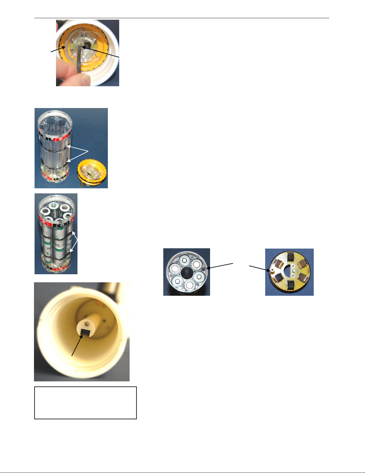
3. Keep the handle in an upright position. Holding the edge of the yellow
cover plate, unscrew the cover plate from the battery pack assembly.
Note: Older SBE 37-SM MicroCATs use a battery pack with a red cover
plate; the wiring of that pack is different from this one, and cannot be
used with this 37-SM.
4. Roll the 2 O-rings on the outside of the battery pack out of their grooves.
5. Insert each cell into the pack, alternating positive (+) end first and
negative (-) end first to match the labels on the pack.
6. Roll the 2 O-rings on the outside of the battery pack into place in the
grooves. The O-rings compress the side of the battery pack and hold the
cells tightly in place in the pack.
7. Reinstall the battery pack cover plate:
A. Align the pin on the battery pack cover plate PCB with the post hole
in the battery pack housing.
B. Place the handle in an upright position. Screw the yellow cover plate
onto the battery pack assembly. Ensure the cover is tightly screwed
on to provide a reliable electrical contact.
8. Replace the battery pack assembly in the housing:
A. Align the D-shaped opening in the cover plate with the pins on the
shaft. Lower the assembly slowly into the housing, and once aligned,
push gently to mate the banana plugs on the battery compartment
bulkhead with the lower PCB. A post at the bottom of the battery
compartment mates with a hole in the battery pack’s lower PCB to
prevent improper alignment.
B. Secure the assembly to the shaft with the captured screw, using the
7/64-inch Allen wrench. Ensure the screw is tight to provide a
reliable electrical contact.
9. Reinstall the I/O connector end cap:
A. Remove any water from the O-rings and mating surfaces in the
housing with a lint-free cloth or tissue. Inspect the O-rings and
mating surfaces for dirt, nicks, and cuts. Clean as necessary. Apply a
light coat of O-ring lubricant (Parker Super O Lube) to the O-rings
and mating surfaces.
B. Plug the female end of the Molex connector onto the pins.
C. Carefully fit the end cap into the housing until the O-rings are
fully seated.
D. Reinstall the 2 cap screws to secure the end cap.
Handle
Loosen
captured
screw
Roll 2
O-rings
out of
grooves
Roll
2 O-rings
into
grooves
after
inserting
cells
Align pin in cover
plate with post hole
in battery pack
Pins on
shaft
CAUTION:
Do not use Parker O-Lube, which
is petroleum based; use only
Super O-Lube.

Manual revision 041 Section 3: Preparing MicroCAT for Deployment SBE 37-SM RS-232
18
Software Installation
Seasoft V2 was designed to work with a PC running Windows 7/8/10
(32-bit or 64-bit).
If not already installed, install Sea-Bird software programs on your computer
using the supplied software CD:
1. Insert the CD in your CD drive.
2. Install software: Double click on SeasoftV2.exe. Follow the dialog box
directions to install the software. The installation program allows you to
install the desired components. Install all the components, or just install
Deployment Endurance Calculator (battery endurance calculator),
SeatermV2 (terminal program launcher for the MicroCAT), and
SBE Data Processing (data processing).
The default location for the software is c:\Program Files\Sea-Bird. Within that
folder is a sub-directory for each program.
If you will be using a USB-to-Serial Port adapter to connect the
instrument to a USB port on your computer: You must install the driver for
the adapter. The driver should have been provided when you purchased the
adapter, or you should be able to download it from the adapter manufacturer’s
website.
Power and Communications Test
The power and communications test will verify that the system works,
prior to deployment.
Test Setup
1. Remove dummy plug (if applicable):
A. By hand, unscrew the locking sleeve from the MicroCAT’s bulkhead
connector. If you must use a wrench or pliers, be careful not to loosen
the bulkhead connector instead of the locking sleeve.
B. Remove the dummy plug from the MicroCAT’s I/O bulkhead
connector by pulling the plug firmly away from the connector.
2. XSG Connector - Install the I/O cable connector, aligning the raised
bump on the side of the connector with the large pin (pin 1 - ground) on
the MicroCAT. OR
MCBH Connector –Install the I/O cable connector, aligning the pins.
3. Connect the I/O cable to your computer’s serial port.
Dummy plug
Locking
sleeve
Notes:
Help files provide detailed
information on the software.
A separate software manual
on the CD-ROM contains
detailed information on
SBE Data Processing.
It is possible to use the MicroCAT
without the SeatermV2 terminal
program by sending direct
commands from a dumb terminal or
terminal emulator, such as Windows
HyperTerminal.
Sea-Bird supplies the current
version of our software when you
purchase an instrument. As software
revisions occur, we post the revised
software on our website. See our
website for the latest software
version number, a description of the
software changes, and instructions
for downloading the software.
Manual revision 041 Section 3: Preparing MicroCAT for Deployment SBE 37-SM RS-232
19
Test
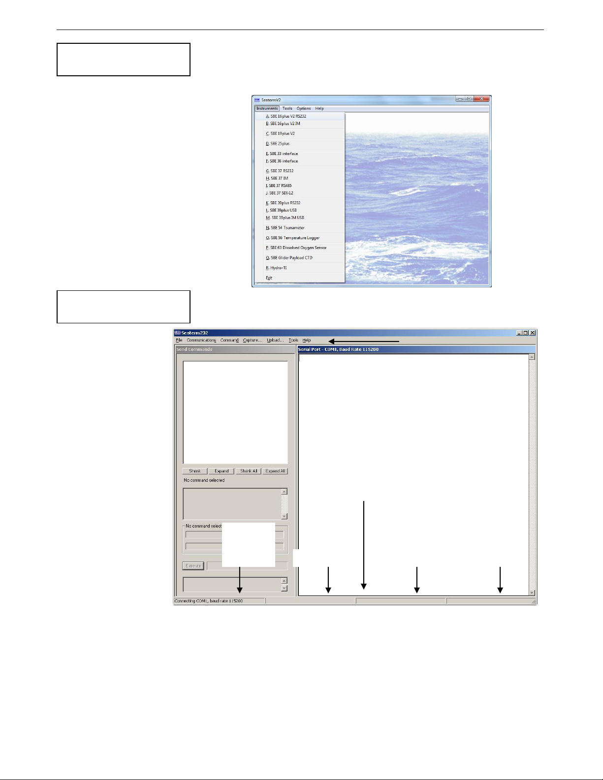
1. Double click on SeatermV2.exe. The main screen looks like this:
SeatermV2 is a launcher, and launches the appropriate terminal program
for the selected instrument.
2. In the Instruments menu, select SBE 37 RS232.
Seaterm232 opens; the main screen looks like this:
Menus –For tasks and frequently executed instrument commands.
Send Commands window –Contains commands applicable to your
MicroCAT. The list appears after you connect to the MicroCAT.
Command/Data Echo Area –Title bar of this window shows
Seaterm232’s current comm port and baud rate. Commands and the
MicroCAT responses are echoed here. Additionally, a command can
be manually typed or pasted (ctrl + V) here. Note that the MicroCAT
must be connected and awake for it to respond to a command.
Status bar –Provides connection, upload, script, and capture status
information.
Note:
See SeatermV2’s Help files.
If uploading
- upload file name.
If sending XML script
–script file name
Capture
status
Progress bar for
uploading data
Status –
Ready,
Uploading,
Finished
Upload, etc.
Status Bar
Command/Data Echo Area
Send Commands
Window
Menus
Note:
See Seaterm232’s Help files.

Manual revision 041 Section 3: Preparing MicroCAT for Deployment SBE 37-SM RS-232
20
Following is a description of the menus:
Menu
Description
Equivalent Command*
File
Load command file –opens selected .XML
command file, and fills Send Commands
window with commands.
Unload command file –closes command
file, and removes commands from Send
Commands window.
Exit - Exit program.
-
Communications
Configure –Establish communication
parameters (comm port and baud rate).
Connect –connect to comm port.
Disconnect –disconnect from
comm port.
Disconnect and reconnect –may be useful
if instrument has stopped responding.
-
Command
Abort –interrupt and stop MicroCAT’s
response.
Send 5 second break (not applicable to this
SBE 37-SMP).
Send stop command.
Set local time–Set date and time to time
sent by timekeeping software on your
computer; accuracy ± 25 msec of time
provided by computer.
Set UTC Time (Greenwich Mean Time) –
Set date and time to time sent by
timekeeping software on your computer;
accuracy ± 25 msec of time provided by
computer.
(press Esc key several
times for Abort)
Stop
DateTime=
DateTime=
Capture
Capture instrument responses on screen to
file, to save real-time data or use for
diagnostics. File has .cap extension. Click
Capture menu again to turn off capture.
Capture status displays in Status bar.
—
Upload
Upload data stored in memory, in a format
that Sea-Bird’s data processing software can
use. Uploaded data has .xml extension, and
is then automatically converted to a .hex and
a .xmlcon file that can be used in SBE Data
Processing’s Data Conversion module.
Before using Upload: stop logging by
sending Stop.
Several status commands
and appropriate data
upload command as
applicable to user
selection of range of data
to upload (use Upload
menu if you will be
processing data with
SBE Data Processing)
Tools
Diagnostics log - Keep a diagnostics log.
Convert .XML data file –Using Upload
menu automatically does this conversion;
tool is available if there was a problem
with the automatic conversion.
Send script –Send XML script to
MicroCAT. May be useful if you have a
number of MicroCATs to program with
same setup.
-
*See Command Descriptions in Section 4: Deploying and Operating MicroCAT.
Note:
Set local time and Set
UTC time are disabled if
the baud rate in
Seaterm232 is set to
115200, because the
software cannot reliably
set the time at that baud.
Table of contents
Other Sea-Bird Scientific Data Logger manuals


Popular Data Logger manuals by other brands


Extech Instruments
Extech Instruments TM500 user guide

Agrowtek
Agrowtek GrowControl INSTALLATION & USER OPERATION MANUAL

Gemini
Gemini Tinyview TV-0020 manual

GE
GE Bently Nevada SCOUT200 Series quick start guide

greenTEG
greenTEG gSKIN U-Value Kit instruction manual

In-situ
In-situ Tube 300S quick start guide