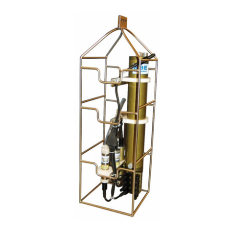
Sea-Bird Scientific SBE 25plus Sealogger CTD Quick manual

25plus BUM
SBE 25plus Sealogger CTD
09/2022, Edition A
Basic user manual
Manual del usuario básico
Basic user manual
Manuale di base per l'utente
Basic user manual

Table of Contents
English..............................................................................................................................3
Español.......................................................................................................................... 11
Français......................................................................................................................... 20
Italiano............................................................................................................................ 29
中文................................................................................................................................. 38
2

Table of Contents
1 Sealogger quick start guide on page 3
2 Specifications on page 3
3 Replace batteries on page 7
4 General information on page 9
Section 1 Sealogger quick start guide
This quick start guide and user manual applies to the SBE 25plus Sealogger.
The full user manual, with details about setup, operation, and maintenance can be found on the
manufacturer's website. Refer to the full user manual for details about the topics shown in
italics.
What's in the box:
• CD—has software, calibration files, documentation
• Dummy plug and lock collar
• Data I/O cable to connect the sensor to a PC
• Spare hardware and O-ring kit.
1. Install the manufacturer-supplied software on a PC. Refer to Install software and set up sensor for
details.
2. Connect the data I/O cable to the sensor and the PC and double-click on SeaTermV2.exe to start
the software.
3. Set up the sensor for deployment.
a. If necessary, install the 12 D-cell alkaline batteries.
b. If necessary, make sure that all data stored in the sensor is transmitted to a PC.
c. Set the date and time and configure the data collection settings.
d. Send the DS and DC commands to verify setup.
4. Remove the yellow protective label from the plumbing intake and exhaust.
5. Deploy the sensor. For most applications, make sure the connector is at the bottom (lowest
point).
6. Immediately after the sensor is recovered from a deployment:
a. Transmit data from the sensor to a PC. Refer to Transmit and convert data for details.
b. Use the software to turn off the sensor.
c. Flush the sensor with fresh water.
d. Keep the sensor out of direct sunlight between deployments.
7. Refer to Recover sensor from deployment for details to prepare the sensor for short- or long-term
storage.
Section 2 Specifications
2.1 Mechanical
Weight, 600 m, plastic, in air,
water
Weight, 6800 m, titanium, in air,
water
Cage, in air, water
20.0, 11.5 kg 22.5, 13.5 kg 6.7, 5.9 kg
English 3

2.1.1 Connectors and cables
J3 auxiliary differential input 6, 7
Contact Function Contact Function MCBH6MP
1 Common 4 Voltage 7 signal
2 Voltage 6 signal 5 Voltage 7 common
3 Voltage 6 common 6 Auxiliary power out
J2 auxiliary differential input 4, 5
Contact Function Contact Function MCBH6MP
1 Common 4 Voltage 5 signal
2 Voltage 4 signal 5 Voltage 5 common
3 Voltage 4 common 6 Auxiliary power out
J1 auxiliary differential input 2, 3
Contact Function Contact Function MCBH6MP
1 Common 4 Voltage 3 signal
2 Voltage 2 signal 5 Voltage 3 common
3 Voltage 2 common 6 Auxiliary power out
J0 auxiliary differential input 0, 1
Contact Function Contact Function MCBH6MP
1 Common 4 Voltage 1 signal
2 Voltage 0 signal 5 Voltage 1 common
3 Voltage 0 common 6 Auxiliary power out
4 English

Connector Contact Function MCBH3MP
J4 Conductivity 1 Common
2 Conductivity frequency
3 Auxiliary power out
Connector Contact Function MCBH3MP
J5 Temperature 1 Common
2 Temperature frequency
3 Auxiliary power out
J6 auxiliary serial input 1, 2
Contact Function Contact Function MCBH6MP
1 Common 4 Serial 2 data RX
2 Serial 1 data RX 5 Serial 2 data TX
3 Serial 1 data TX 6 Auxiliary power out
J7 data I/O, pump, external power
Contact Function Contact Function MCBH6MP
1 Common 4 Pump power common
2 RS232 data RX 5 Pump power
3 RS232 data TX 6 Auxiliary power in, 14–20 VDC
Figure 1 Y cable
English 5

Figure 2 Data I/O cable
Figure 3 SBE 4 to CTD cable
Notes:
• The Y cable from J7 connects to the pump and a data I/O power cable, so the system can connect
to a PC for setup and to transmit data, and to externally power the 25plus.
•Auxiliary sensors that draw more than 1 amp, even momentarily, must be connected to
J3 or J6. Refer to integration of high current-draw sensors for details.
2.1.2 Dimensions
6 English

2.2 Communications
Memory 2 GB
Communication interface RS232
Data collection rate 16 Hz
2.3 Electrical
Input from external power supply 14–20 VDC
Internal batteries, 12 alkaline D-cells 18.6 Ah
Battery life with current draw less than 500 mA 14 Ah
Battery life with current draw more than 500 mA 5 Ah
Current draw, operation (no auxiliary sensors or pump) 95 mA
Current draw, pump 150 mA
Current draw, communications 70 mA
Current draw, low power (powered by internal batteries) 70 µA
Current draw, low power (powered by external batteries) 175 µA
2.4 Analytical
Parameter Range Accuracy Resolution
Conductivity 0–70 mS/cm ±0.003 mS/cm 0.0001 mS/cm
Temperature -5–35 °C ±0.002 °C (-5–35 °C) 0.0001 °C
Pressure various to 7000 m ±0.1% full scale range 0.002% full scale range
Section 3 Replace batteries
WARNING
Explosion hazard. If the batteries are not installed correctly, explosive gases can be released. Make
sure that the batteries are of the same approved chemical type and are inserted in the correct
orientation.
WARNING
If the user thinks that a sensor has water in the pressure housing: Disconnect the sensor from any
power supply. Put on safety glasses and make sure that the sensor is pointed away from the body
and other people. In a well ventilated area, use the purge port (if the sensor is so equipped), or very
SLOWLY loosen the bulkhead connector to let the pressure release.
WARNING
If the user thinks that the alkaline batteries have leaks, pressure may have built up inside of the
pressure housing. Follow ESD protocols to release internal pressure. Put on safety glasses and
protective gloves and make sure that the sensor is pointed away from the body and other people. In
a well ventilated very SLOWLY loosen the bulkhead connector to release the pressure. Keep away
from heat, sparks, flame, and other sources of ignition. Do not smoke.
English 7

CAUTION
The pressure housing contains Electrostatic Discharge (ESD) sensitive parts and assemblies that
are susceptible to damage from ESD. Follow ESD protocols:
• Put on protective eye wear before you open the pressure housing.
• Any electrostatic charge on the body of the human operator must be released before the
pressure housing is opened: put a hand on a grounded surface, or better, wear a grounded
antistatic wrist strap.
• At a minimum, wear short-sleeved antistatic clothing, such as cotton, or better, wear an antistatic
smock for this service activity. Do not wear a sweater, fleece or polyester-based clothing.
• At a minimum, use a workstation with a wood or metal tabletop, or better, a tabletop that
dissipates static. Do not use a workstation with a synthetic or polymeric-based tabletop.
N O T I C E
Blue Moly™ and Dow Corning®4 lubricants are electrically conductive. Keep away from electrical components.
The 25plus uses 12 Duracell® MN1300, LR20 D-cell alkaline batteries.
Remove the batteries if the 25plus will be stored for a long period. Store batteries at a temperature
between 5 °C and 30 °C.
1. Remove the battery end flange (opposite the end with connectors):
a. Clean the outside of the end flange and the housing. Make sure all parts are dry.
b. Turn the end flange counter-clockwise to remove it.
c. Use a lint-free cloth or tissue to remove any water from the O-ring surfaces inside the
housing.
d. Make sure to protect the O-ring from damage or contamination.
2. It is not necessary to remove the battery pack from the housing, but to do this:
a. Use a 9/64 inch hex wrench to loosen the captured post that attaches the battery pack in the
housing.
b. Pull the handle up and then pull the battery pack from the housing.
c. Turn the battery pack over and remove the batteries.
d. Install new batteries with the + terminals up. Refer to the marks on the side of the battery
pack.
8 English

3. Install the cover on the battery pack again:
a. The cover fits into the battery pack only one way. The opening next to the USB mark must
align with the USB connector in the battery pack.
b. Tighten the cover until there is no gap between the bottom O-ring and the battery pack
housing.
4. If the battery pack was removed from the pressure housing, use the banana plug sockets on the
bottom plate of the battery pack to verify that the battery voltage is approximately 19.5 volts.
5. Install the battery pack in the pressure housing if it was removed.
a. Make sure there is no water on any surface.
b. The O-rings must be pristine. Apply a small quantity of Parker Super O-Lube on any new O-
rings, then carefully install the new ones.
6. Carefully put the end flange in to the pressure housing and tighten into position. Use a wrench if
necessary.
Section 4 General information
WARNING
This product can expose the user to chemicals with silica, crystalline (airborne particles of respirable size), which
is known to the State of California to cause cancer and birth defects or other reproductive harm. For more
information, go to www.P65Warnings.ca.gov.
Revised editions of this user manual are on the manufacturer's website.
English 9

4.1 Service and support
The manufacturer recommends that sensors be sent back to the manufacturer annually to be
cleaned, calibrated, and for standard maintenance.
Refer to the website for FAQs and technical notes, or contact the manufacturer for support at
[email protected]. Do the steps below to send a sensor back to the manufacturer.
1. Complete the online Return Merchandise Authorization (RMA) form or contact the manufacturer.
Note: The manufacturer is not responsible for damage to the sensor during return shipment.
2. Remove all batteries from the sensor, if so equipped.
3. Remove all anti-fouling treatments and devices.
Note: The manufacturer will not accept sensors that have been treated with anti-fouling compounds for service
or repair. This includes AF 24173 devices, tri-butyl tin, marine anti-fouling paint, ablative coatings, etc.
4. Use the sensor's original ruggedized shipping case to send the sensor back to the manufacturer.
5. Write the RMA number on the outside of the shipping case and on the packing list.
6. Use 3rd-day air to ship the sensor back to the manufacturer. Do not use ground shipping.
7. The manufacturer will supply all replacement parts and labor and pay to send the sensor back to
the user via 3rd-day air shipping.
4.2 Warranty
Refer to the manufacturer's website for warranty information (seabird.com/warranty).
4.3 China RoHS disclosure table
Name of Part Hazardous substance or element in product
Pb Hg Cd Cr(VI)) PBB PBDE
PCBs X O O O O O
Conductivity cell X O O O O O
Battery pack O O O O O O
Cables X O O O O O
Housing O O O O O O
Plumbing O O O O O O
Frame O O O O O O
Mounting hardware O O O O O O
Accessories O O O O O O
This table is compiled to the SJ/T 11364 standard.
O: This hazardous substance is below the specified limits as described in GB/T 26572.
X: This hazardous substance is above the specified limits as described in GB/T 26572.
10 English

Tabla de contenidos
1 Sealogger quick start guide en la página 11
2 Especificaciones en la página 11
3 Cambio de las pilas en la página 16
4 Información general en la página 18
Sección 1 Sealogger quick start guide
This quick start guide and user manual applies to the SBE 25plus Sealogger.
The full user manual, with details about setup, operation, and maintenance can be found on the
manufacturer's website. Refer to the full user manual for details about the topics shown in
italics.
What's in the box:
• CD—has software, calibration files, documentation
• Dummy plug and lock collar
• Data I/O cable to connect the sensor to a PC
• Spare hardware and O-ring kit.
1. Install the manufacturer-supplied software on a PC. Refer to Install software and set up sensor for
details.
2. Connect the data I/O cable to the sensor and the PC and double-click on SeaTermV2.exe to start
the software.
3. Set up the sensor for deployment.
a. If necessary, install the 12 D-cell alkaline batteries.
b. If necessary, make sure that all data stored in the sensor is transmitted to a PC.
c. Set the date and time and configure the data collection settings.
d. Send the DS and DC commands to verify setup.
4. Remove the yellow protective label from the plumbing intake and exhaust.
5. Deploy the sensor. For most applications, make sure the connector is at the bottom (lowest
point).
6. Immediately after the sensor is recovered from a deployment:
a. Transmit data from the sensor to a PC. Refer to Transmit and convert data for details.
b. Use the software to turn off the sensor.
c. Flush the sensor with fresh water.
d. Keep the sensor out of direct sunlight between deployments.
7. Refer to Recover sensor from deployment for details to prepare the sensor for short- or long-term
storage.
Sección 2 Especificaciones
2.1 Mecánica
Peso, 600 m, plástico, en
aire/agua
Peso, 6800 m, titanio, en
aire/agua
Jaula, en aire/agua
20,0/11,5 kg 22,5/13,5 kg 6,7/5,9 kg
Español 11

2.1.1 Conectores y cables
J3: entrada diferencial auxiliar 6, 7
Contacto Función Contacto Función MCBH6MP
1 Común 4 Señal de tensión 7
2 Señal de tensión 6 5 Común de tensión 7
3 Común de tensión 6 6 Salida de alimentación auxiliar
J2: entrada diferencial auxiliar 4, 5
Contacto Función Contacto Función MCBH6MP
1 Común 4 Señal de tensión 5
2 Señal de tensión 4 5 Común de tensión 5
3 Común de tensión 4 6 Salida de alimentación auxiliar
J1: entrada diferencial auxiliar 2, 3
Contacto Función Contacto Función MCBH6MP
1 Común 4 Señal de tensión 3
2 Señal de tensión 2 5 Común de tensión 3
3 Común de tensión 2 6 Salida de alimentación auxiliar
J0: entrada diferencial auxiliar 0, 1
Contacto Función Contacto Función MCBH6MP
1 Común 4 Señal de tensión 1
2 Señal de tensión 0 5 Común de tensión 1
3 Común de tensión 0 6 Salida de alimentación auxiliar
12 Español

Conector Contacto Función MCBH3MP
J4: conductividad 1 Común
2 Frecuencia de conductividad
3 Salida de alimentación auxiliar
Conector Contacto Función MCBH3MP
J5: temperatura 1 Común
2 Frecuencia de temperatura
3 Salida de alimentación auxiliar
J6: entrada auxiliar en serie 1, 2
Contacto Función Contacto Función MCBH6MP
1 Común 4 Datos serie 2 RX
2 Datos serie 1 RX 5 Datos serie 2 TX
3 Datos serie 1 TX 6 Salida de alimentación auxiliar
J7: E/S de datos, bomba, alimentación externa
Contacto Función Contacto Función MCBH6MP
1 Común 4 Alimentación de la bomba común
2 RS232 datos RX 5 Alimentación de la bomba
3 RS232 datos TX 6 Entrada de alimentación auxiliar,
14-20 V CC
Figura 1 Cable en Y
Español 13

Figura 2 Cable de E/S de datos
Figura 3 Cable SBE 4 a CTD
Notas:
• El cable en Y de J7 se conecta a la bomba y a un cable de alimentación de E/S de datos, de
modo que el sistema se puede conectar a un PC para la configuración y transmisión de datos, así
como para suministrar alimentación externa al modelo 25plus.
•Los sensores auxiliares que consumen más de 1 amperio, incluso momentáneamente,
deben conectarse a J3 o J6. Consulte la sección Integración de sensores de alto consumo
de corriente para obtener más información.
14 Español

2.1.2 Dimensiones
2.2 Comunicaciones
Memoria 2 GB
Interfase de comunicación RS232
Velocidad de recopilación de
datos
16 Hz
2.3 Electricidad
Entrada de fuente de alimentación externa 14-20 V CC
Pilas internas, 12 pilas alcalinas D 18,6 Ah
Duración de la batería con un consumo de corriente inferior a 500 mA 14 Ah
Duración de la batería con un consumo de corriente superior a 500 mA 5 Ah
Consumo de corriente, funcionamiento (sin sensores auxiliares ni bomba) 95 mA
Consumo de corriente, bomba 150 mA
Consumo de corriente, comunicaciones 70 mA
Español 15

Consumo de corriente, baja potencia (alimentado por pilas internas) 70 µA
Consumo de corriente, baja potencia (alimentado por pilas externas) 175 µA
2.4 Analíticas
Parámetro Intervalo Exactitud Resolución
Conductividad 0-70 mS/cm ±0,003 mS/cm 0,0001 mS/cm
Temperatura De -5 a 35 °C ±0,002 °C (-5 a 35 °C) 0,0001 °C
Presión Hasta 7000 m ±0,1 % del intervalo de
escala completa
0,002 % del intervalo de
escala completa
Sección 3 Cambio de las pilas
ADVERTENCIA
Peligro de explosión. Si las pilas no están instaladas correctamente, se pueden liberar gases
explosivos. Asegúrese de que las pilas son del mismo tipo y material químico aprobado y están
insertadas en la orientación correcta.
ADVERTENCIA
Si el usuario cree que un sensor tiene agua en la carcasa de presión, desconecte el sensor de toda
fuente de alimentación. Utilice gafas de protección y asegúrese de que el sensor apunta lejos de su
cuerpo y del de cualquier otra persona. Si se encuentra en una zona bien ventilada, utilice el puerto
de purga (si el sensor está equipado con él), o afloje muy LENTAMENTE el conector de mamparo
para dejar que se libere la presión.
ADVERTENCIA
Si el usuario cree que las pilas alcalinas presentan fugas, es posible que se haya acumulado
presión en el interior de la carcasa de presión. Siga los protocolos de ESD para liberar la presión
interna. Utilice gafas y guantes de protección y asegúrese de que el sensor apunta lejos de su
cuerpo y del de cualquier otra persona. Si se encuentra en una zona bien ventilada, afloje muy
LENTAMENTE el conector de mamparo para liberar la presión. Mantener lejos del calor, las
chispas, las llamas y cualquier otra fuente de ignición. No fumar.
PRECAUCIÓN
La carcasa de presión contiene piezas y conjuntos sensibles a las descargas electrostáticas (ESD)
susceptibles de sufrir daños por ESD. Siga los protocolos de ESD:
• Utilice protección ocular al abrir la carcasa de presión.
• Cualquier carga electrostática en el cuerpo del operador humano debe liberarse antes de abrir la
carcasa de presión: coloque una mano sobre una superficie con conexión a tierra o, mejor aún,
utilice una muñequera antiestática con conexión a tierra.
• Cuando realice esta actividad de servicio, use ropa antiestática de manga corta (por ejemplo, de
algodón) o una bata antiestática. No use prendas como sudaderas o forros polares ni ropa de
poliéster.
• Utilice un banco de trabajo con un tablero de madera o metal, o mejor aún, un tablero que disipe
la electricidad estática. No utilice un banco de trabajo con un tablero sintético o de polímero.
A V I S O
Los lubricantes Blue Moly™ y Dow Corning®4 son conductores de la electricidad. Manténgase alejado de los
componentes eléctricos.
El modelo 25plus utiliza 12 pilas alcalinas D Duracell® MN1300, LR20.
Extraiga las pilas antes de almacenar el modelo 25plus durante un largo periodo de tiempo. Guarde
las pilas a una temperatura entre 5 °C y 30 °C.
16 Español

1. Retire la brida final del compartimento de las pilas (en el extremo opuesto al de los conectores):
a. Limpie el exterior de la brida final y la carcasa. Asegúrese de que todas las piezas estén
secas.
b. Gire la brida final hacia la izquierda para retirarla.
c. Utilice un paño o toallita sin pelusa para eliminar el agua de las superficies de la junta tórica
en el interior de la carcasa.
d. Asegúrese de proteger la junta tórica de daños o contaminación.
2. No es necesario extraer el bloque de pilas de la carcasa, pero para ello:
a. Utilice una llave hexagonal de 9/64" para aflojar el poste cautivo que fija el bloque de pilas a
la carcasa.
b. Tire del asa hacia arriba y, a continuación, extraiga el bloque de pilas de la carcasa.
c. Dele la vuelta al bloque de pilas y extraiga las pilas.
d. Instale pilas nuevas con los terminales + hacia arriba. Consulte las marcas en el lateral del
bloque de pilas.
3. Vuelva a colocar la tapa del bloque de pilas:
a. La tapa encaja en el bloque de pilas de una sola manera. La abertura situada junto a la
marca USB debe estar alineada con el conector USB del bloque de pilas.
Español 17

b. Apriete la tapa hasta que no quede espacio entre la junta tórica inferior y la carcasa del
bloque de pilas.
4. Si se ha extraído el bloque de pilas de la carcasa de presión, utilice las tomas de clavija tipo
banana de la placa inferior del bloque de pilas para verificar que la tensión de las pilas es de
aproximadamente 19,5 voltios.
5. Instale el bloque de pilas en la carcasa de presión si se ha extraído.
a. Asegúrese de que no haya agua en ninguna superficie.
b. Las juntas tóricas deben estar en perfecto estado. Aplique una pequeña cantidad de Parker
Super O-Lube en las juntas tóricas nuevas y, a continuación, instálelas con cuidado.
6. Coloque con cuidado la brida final en la carcasa de presión y apriétela en su posición. Utilice una
llave si fuera necesario.
Sección 4 Información general
ADVERTENCIA
Este producto puede exponer al usuario a sustancias químicas con silicio cristalino (partículas en el aire de
tamaño respirable) que, según el estado de California (EE. UU.), causan cáncer y defectos congénitos u otros
daños reproductivos. Para obtener más información, visite www.P65Warnings.ca.gov.
Las ediciones revisadas de este manual del usuario se encuentran en la página web del fabricante.
4.1 Mantenimiento y asistencia técnica
El fabricante recomienda enviar los sensores a fábrica una vez al año para su limpieza, calibración y
mantenimiento estándar.
Consulte las preguntas frecuentes y las notas técnicas en el sitio web o póngase en contacto con el
fabricante para obtener asistencia en [email protected]. Lleve a cabo los pasos siguientes para
devolver el sensor al fabricante.
1. Rellene el formulario de autorización para devolución de producto (RMA) o póngase en contacto
con el fabricante.
Nota: El fabricante no es responsable de los daños que se provoquen al sensor durante el envío.
2. Retire todas las pilas del sensor, si las tiene.
3. Retire todos los tratamientos y dispositivos antiincrustaciones.
Nota: El fabricante no aceptará los sensores que se hayan tratado con compuestos antiincrustantes para su
reparación o mantenimiento. Entre ellos se incluyen dispositivos AF 24173 AF, tributilestaño, pintura
antiincrustante para uso naval, revestimientos ablativos, etc.
4. Utilice la caja de transporte robusta original del sensor para devolverlo al fabricante.
18 Español

5. Escriba el número RMA en el exterior de la caja y en la lista de embalaje.
6. Utilice la modalidad de envío aéreo de tres días para devolver el sensor al fabricante. No utilice
una modalidad de envío terrestre.
7. El fabricante suministrará todas las piezas de recambio y la mano de obra, y, además pagará
para devolver el sensor al usuario mediante modo de envío de 3 días.
4.2 Garantía
Consulte el sitio web del fabricante para obtener más información sobre la garantía
(seabird.com/warranty).
4.3 Tabla de divulgación de RoHS en China
Nombre de la pieza Sustancia o elemento peligrosos en el producto
Pb Hg Cd Cr (VI) PBB PBDE
PCB X O O O O O
Celda de conductividad X O O O O O
Bloque de pilas O O O O O O
Cables X O O O O O
Carcasa O O O O O O
Conexiones hidráulicas O O O O O O
Chasis O O O O O O
Tornillería de montaje O O O O O O
Accesorios O O O O O O
Esta tabla se ha elaborado según la norma SJ/T 11364.
O: Esta sustancia peligrosa está por debajo de los límites especificados en GB/T 26572.
X: Esta sustancia peligrosa está por encima de los límites especificados en GB/T 26572.
Español 19

Table des matières
1 Guide de démarrage rapide Sealogger à la page 20
2 Caractéristiques techniques à la page 20
3 Remplacement des piles à la page 25
4 Généralités à la page 27
Section 1 Guide de démarrage rapide Sealogger
Le guide de démarrage rapide et le manuel d'utilisation s'appliquent au SBE 25plus Sealogger.
Le manuel d'utilisation complet, comprenant des informations sur la configuration, l'utilisation et la
maintenance, est disponible sur le site Web du fabricant. Reportez-vous au manuel d'utilisation
complet pour plus d'informations sur les sujets indiqués en italique.
Contenu de la boîte :
• CD : logiciel, fichiers d'étalonnage, documentation
• Un bouchon factice et collier de verrouillage
• Un câble d'E/S de données pour connecter le capteur à un PC
• Le matériel de rechange et un kit de joints toriques.
1. Installez le logiciel fourni par le fabricant sur un PC. Reportez-vous à la section relative à
l'installation du logiciel et la configuration du capteur pour plus d'informations.
2. Connectez le câble d'E/S de données au capteur et au PC, puis double-cliquez sur
SeaTermV2.exe pour lancer le logiciel.
3. Configurez le capteur pour le déploiement.
a. Si nécessaire, installez les 12 piles alcalines de type D.
b. Si nécessaire, assurez-vous que toutes les données stockées dans le capteur sont
transmises à un PC.
c. Réglez la date et l'heure et configurez les paramètres de collecte des données.
d. Envoyez les commandes DS et DC pour vérifier la configuration.
4. Retirez l'étiquette de protection jaune de l'admission et de l'échappement de la tuyauterie.
5. Déployez le capteur. Pour la plupart des applications, assurez-vous que le connecteur se trouve
en bas (au point le plus bas).
6. Immédiatement après avoir récupéré le capteur suite à un déploiement :
a. Transmettez les données du capteur à un PC. Reportez-vous à la section relative à la
transmission et la conversion des données pour plus d'informations.
b. Utilisez le logiciel pour éteindre le capteur.
c. Rincez le capteur à l'eau douce.
d. Conservez le capteur à l'abri de la lumière directe du soleil entre les déploiements.
7. Reportez-vous à la section relative à la récupération d'un capteur après déploiement pour plus
d'informations sur la préparation du capteur à un entreposage à court ou long terme.
Section 2 Caractéristiques techniques
2.1 Caractéristiques mécaniques
Poids, 600 m, plastique, dans
l'air, dans l'eau
Poids, 6800 m, titane, dans l'air,
dans l'eau
Cage, dans l'air, dans l'eau
20,0, 11,5 kg 22,5, 13,5 kg 6,7, 5,9 kg
20 Français
This manual suits for next models
1
Table of contents
Languages:
Other Sea-Bird Scientific Data Logger manuals
Popular Data Logger manuals by other brands

National Instruments
National Instruments NI PXI-7852 user manual
LOVATO ELECTRIC
LOVATO ELECTRIC DME CD instruction manual
Spectrum Technologies
Spectrum Technologies WatchDog 1000 Data Shuttle Series product manual
TempSen
TempSen ITAG3 Series quick guide
Whadda
Whadda Arduino WPSH202 manual
MSR
MSR MSR175 Brief instructions
