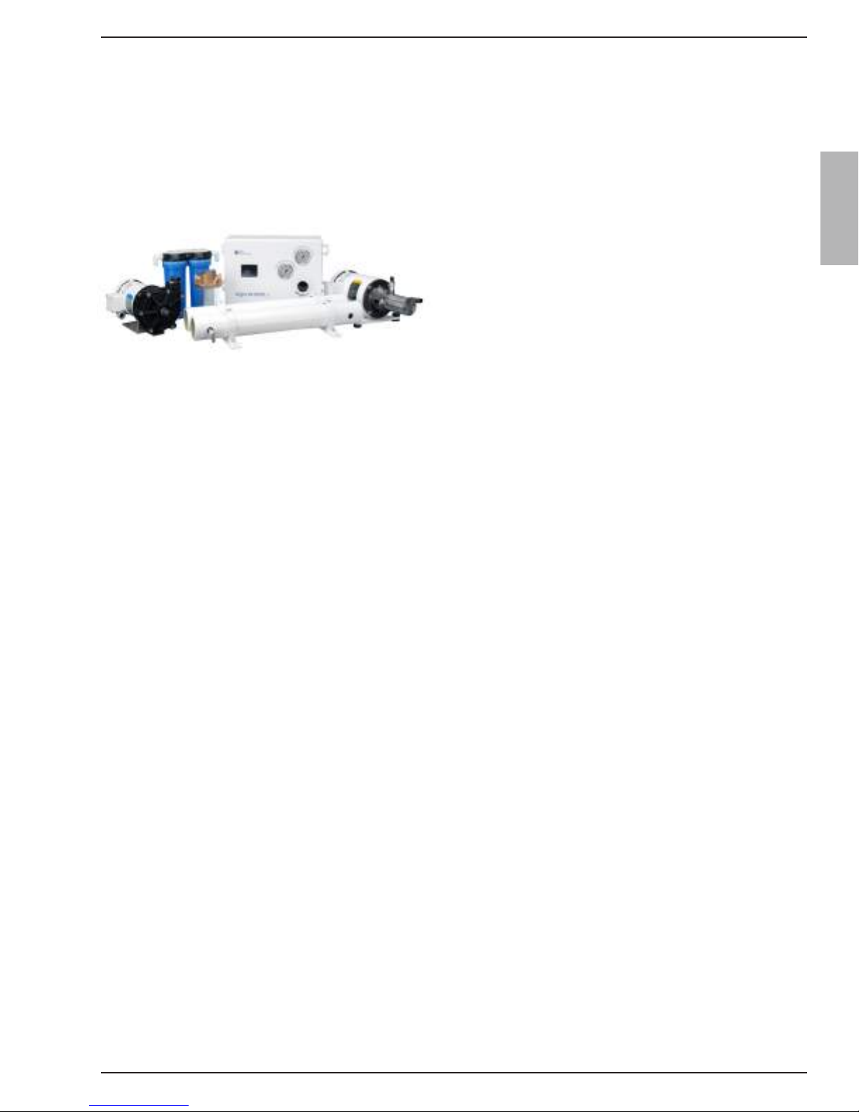
Aqua Whisper DX Modular 450-1800
Page i
PREFACE
Thank you for your purchase of a Sea Recovery Aqua Whisper
Reverse Osmosis Desalination System. This manual contains
instructions for the installation, operation, maintenance,
and repair of the Sea Recovery Desalination System. This
information is provided to ensure extended life and safe
operation of your Sea Recovery system.
Please read this manual thoroughly before installation
or operation, and keep it for future reference. A better
understanding of the system ensures optimum performance
and longer service life.
Sea Recovery’s Reverse Osmosis Desalination Systems are
designed and engineered to function as a complete working
unit. Generally speaking, the performance of each component
within the System is dependent on the component prior to
it and governs the performance of all components after it.
Proper performance of the system is thus dependent upon
proper operation of every single component within the system.
The intent of this manual is to allow the operator to become
familiar with each component within the Sea Recovery system.
By understanding the function, importance, and normal
operation of each component within each subsystem of the
unit, the operator can readily diagnose minor problems, which
if detected early are usually easily corrected. However, if left
unattended, a problem in one component eventually affects the
rest of the system and leads to further repairs.
The manual is divided into sections that address different
subject matter. Each section should be reviewed before
operating the Reverse Osmosis Desalination system.
The major documented cause of failures and problems are
from the use of third party, non Sea Recovery, parts, from
improper installation, and from improper operation:
The use of third party, non Sea Recovery, consumable, spares,
and assemblies will damage the Sea Recovery system and/
or specific components within the system. Do not use parts,
components from any source other than Sea Recovery. Use of
third party, non Sea Recovery, components will void any and
all warranty of the system and/or void the effected component
within the system.
Sea Recovery maintains inventory for immediate shipment and
our Service Dealers throughout the world maintain stock of Sea
Recovery parts. Always insist on Sea Recovery supplied parts
for your system in order to avoid failures, eliminate problems,
and maintain your Sea Recovery Warranty.
Follow the Installation and Operation Instructions in this manual.
From time to time, Sea Recovery may make programming
changes to the Control Logic.
Other physical production changes may also be made from
time to time and are tracked by Sea Recovery through the
System Serial Number.
Troubleshooting and repair method results can vary
depending on the information that is displayed at the SYSTEM
INFORMATION screen.
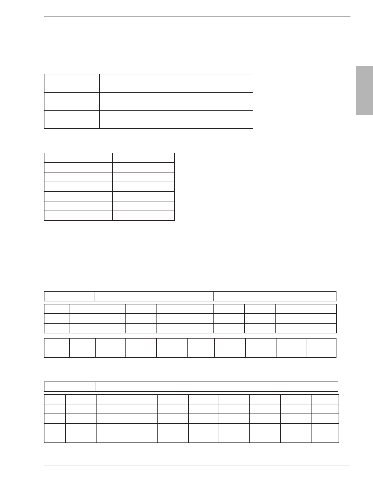
When requesting assistance from Sea Recovery
or Sea Recovery’s service dealers, always:
PROVIDE ALL INFORMATION DISPLAYED
AT THE SYSTEM INFORMATION SCREEN.
SERIAL NUMBER helps us to determine the latest
physical version and configuration of your system which
is necessary to ensure that we provide you with the
correct information or parts.
TYPE tells us the production capacity of your system
which gives us a bench mark in diagnosing product
water flow and pressure concerns.
TIME RUNNING assists us in diagnosing abnormalities
that can occur at given operational time intervals such as
required pump maintenance, or R.O. membrane element
condition.
VERSION allows us to determine the specific sequential
operation of the system based on the version of the
programmed control logic.