Waters ACQUITY Parts list manual

ACQUITY UPLC H-Class
System Guide
715005049
Revision C
Copyright © Waters Corporation 2016
All rights reserved

General information
Copyright notice
© 2010 – 2016 WATERS CORPORATION. PRINTED IN THE UNITED STATES OF AMERICA
AND IN IRELAND. ALL RIGHTS RESERVED. THIS DOCUMENT OR PARTS THEREOF MAY
NOT BE REPRODUCED IN ANY FORM WITHOUT THE WRITTEN PERMISSION OF THE
PUBLISHER.
The information in this document is subject to change without notice and should not be construed
as a commitment by Waters Corporation. Waters Corporation assumes no responsibility for any
errors that may appear in this document. This document is believed to be complete and accurate
at the time of publication. In no event shall Waters Corporation be liable for incidental or
consequential damages in connection with, or arising from, its use. For the most recent revision
of this document, consult the Waters Web site (waters.com).
Trademarks
ACQUITY® is a registered trademark of Waters Corporation.
ACQUITY UPLC® is a registered trademark of Waters Corporation.
Auto•Blend PlusTM is a trademark of Waters Corporation.
Connections INSIGHT® is a registered trademark of Waters Corporation.
eCordTM is a trademark of Waters Corporation.
Empower® is a registered trademark of Waters Corporation.
KEL-F® is a registered trademark of 3M.
Keps® is a registered trademark of Illinois Tool Works Inc.
LAC/ETM is a trademark of Waters Corporation.
MassLynx® is a registered trademark of Waters Corporation.
Millennium® is a registered trademark of Waters Corporation.
MP35NTM is a trademark of SPS Technologies Inc.
PEEKTM is a trademark of Victrex PLC.
PHILLIPS® is a registered trademark of Phillips Screw Company.
August 8, 2016, 715005049 Rev. C
Page ii

PIC® is a registered trademark of Waters Corporation.
Waters® is a registered trademark of Waters Corporation.
Teflon® is a registered trademark of E.I. du Pont de Nemours and Company or its affiliates.
THE SCIENCE OF WHAT'S POSSIBLE® is a registered trademark of Waters Corporation.
TORX® is a registered trademark of Camcar Division, Textron Inc.
TRITON® is a registered trademark of Union Carbide Corporation.
TWEENTM is a trademark of ICI Americas Inc.
UNIFI® is a registered trademark of Waters Corporation.
Waters® is a registered trademark of Waters Corporation.
All other trademarks or registered trademarks are the sole property of their respective owners.
Customer comments
Waters’ Technical Communications organization invites you to report any errors that you
encounter in this document or to suggest ideas for otherwise improving it. Help us better
understand what you expect from our documentation so that we can continuously improve its
accuracy and usability.
We seriously consider every customer comment we receive. You can reach us at
Contacting Waters
Contact Waters with enhancement requests or technical questions regarding the use,
transportation, removal, or disposal of any Waters product. You can reach us via the Internet,
telephone, or conventional mail.
Waters contact information
Contacting medium Information
Internet The Waters Web site includes contact information for Waters locations
worldwide.
Visit www.waters.com
Telephone and fax From the USA or Canada, phone 800-252-4752, or fax 508-872-1990.
For other locations worldwide, phone and fax numbers appear in the
Waters Web site.
August 8, 2016, 715005049 Rev. C
Page iii

Waters contact information (continued)
Contacting medium Information
Conventional mail Waters Corporation
Global Support Services
34 Maple Street
Milford, MA 01757
USA
Safety considerations
Some reagents and samples used with Waters instruments and devices can pose chemical,
biological, or radiological hazards (or any combination thereof). You must know the potentially
hazardous effects of all substances you work with. Always follow Good Laboratory Practice
(GLP), and consult your organization’s standard operating procedures as well as your local
requirements for safety.
Safety hazard symbol notice
Documentation needs to be consulted in all cases where the symbol is used to find out the
nature of the potential hazard and any actions which have to be taken.
Power cord replacement hazard
Warning: To avoid electric shock, use the SVT-type power cord in the United States
and HAR-type (or better) cord in Europe. The main power cord must be replaced only
with one of adequate rating. For information regarding what cord to use in other
countries, contact your local Waters distributor.
Hand crush hazard
Warning: To avoid hazards associated with the reciprocating or rotating parts in the
source, keep hands clear of the regions marked with yellow and gray labels.
High voltage hazard
Warning: To avoid electric shock, do not remove protective panels from system
modules. The components within are not user-serviceable.
August 8, 2016, 715005049 Rev. C
Page iv

Bottle placement prohibition
Warning: To avoid injury from electrical shock or fire, and damage to the equipment, do not
place vessels containing liquid atop the workstation or ancillary equipment or otherwise expose
those units to dripping or splashing liquids.
Prohibited: Do not place vessels containing liquid—such as solvent bottles—atop the
workstation or ancillary equipment or otherwise expose those units to dripping or
splashing liquids.
FCC radiation emissions notice
Changes or modifications not expressly approved by the party responsible for compliance, could
void the user's authority to operate the equipment. This device complies with Part 15 of the FCC
Rules. Operation is subject to the following two conditions: (1) this device may not cause harmful
interference, and (2) this device must accept any interference received, including interference that
may cause undesired operation.
Electrical power safety notice
Do not position the instrument so that it is difficult to disconnect the power cord.
Equipment misuse notice
If equipment is used in a manner not specified by its manufacturer, protections against personal
injury inherent in the equipment’s design can be rendered ineffective.
Safety advisories
Consult the "Safety advisories" appendix in this publication for a comprehensive list of warning
advisories and notices.
Operating the system
When operating the system, follow standard quality-control (QC) procedures and the guidelines
presented in this section.
August 8, 2016, 715005049 Rev. C
Page v

Applicable symbols
Symbol Definition
Manufacturer
Date of manufacture
Authorized representative of the European Community
Confirms that a manufactured product complies with all applicable
European Community directives
or
Australia EMC compliant
Confirms that a manufactured product complies with all applicable United
States and Canadian safety requirements
Consult instructions for use
Alternating current
Electrical and electronic equipment with this symbol may contain
hazardous substances and should not be disposed of as general waste.
For compliance with the Waste Electrical and Electronic Equipment
Directive (WEEE) 2012/19/EU, contact Waters Corporation for the correct
disposal and recycling instructions.
Serial number
REF
Part number catalog number
Audience and purpose
This guide is intended for personnel who operate and maintain the ACQUITY UPLC H-Class
system.
August 8, 2016, 715005049 Rev. C
Page vi

Intended use
Waters designed this system to perform liquid chromatography separations in these
environments:
• Pharmaceutical development and discovery
• Quality assurance and quality control
• Chemical materials
• Environmental
• Food safety
The system is not intended for use in diagnostic applications.
Calibrating
To calibrate LC systems, adopt acceptable calibration methods using at least five standards to
generate a standard curve. The concentration range for standards must include the entire range
of QC samples, typical specimens, and atypical specimens.
When calibrating mass spectrometers, consult the calibration section of the operator’s guide for
the instrument you are calibrating. In cases where an overview and maintenance guide, not an
operator’s guide, accompanies the instrument, consult the instrument’s online Help system for
calibration instructions.
Quality control
Routinely run three QC samples that represent subnormal, normal, and above-normal levels of a
compound. If sample trays are the same or very similar, vary the location of the QC samples in
the trays. Ensure that QC sample results fall within an acceptable range, and evaluate precision
from day to day and run to run. Data collected when QC samples are out of range might not be
valid. Do not report these data until you are certain that the instrument performs satisfactorily.
EMC considerations
Canada spectrum management emissions notice
This class A digital product apparatus complies with Canadian ICES-001.
Cet appareil numérique de la classe A est conforme à la norme NMB-001.
August 8, 2016, 715005049 Rev. C
Page vii

ISM classification: ISM group 1 class B
This classification has been assigned in accordance with IEC CISPR 11 Industrial Scientific and
Medical (ISM) instrument requirements.
Group 1 products apply to intentionally generated and/or used conductively coupled radio-
frequency energy that is necessary for the internal functioning of the equipment.
Class B products are suitable for use in both commercial and residential locations and can be
directly connected to a low voltage, power-supply network.
EC authorized representative
Address Waters Corporation
Stamford Avenue
Altrincham Road
Wilmslow SK9 4AX UK
Telephone +44-161-946-2400
Fax +44-161-946-2480
Contact Quality manager
August 8, 2016, 715005049 Rev. C
Page viii

Table of contents
General information .......................................................................................................ii
Copyright notice ..................................................................................................................................... ii
Trademarks............................................................................................................................................ ii
Customer comments..............................................................................................................................iii
Contacting Waters .................................................................................................................................iii
Safety considerations............................................................................................................................ iv
Safety hazard symbol notice .......................................................................................................... iv
Power cord replacement hazard..................................................................................................... iv
Hand crush hazard ......................................................................................................................... iv
High voltage hazard........................................................................................................................ iv
Bottle placement prohibition ............................................................................................................ v
FCC radiation emissions notice....................................................................................................... v
Electrical power safety notice.......................................................................................................... v
Equipment misuse notice ................................................................................................................ v
Safety advisories ............................................................................................................................. v
Operating the system............................................................................................................................. v
Applicable symbols......................................................................................................................... vi
Audience and purpose.................................................................................................................... vi
Intended use...................................................................................................................................vii
Calibrating ......................................................................................................................................vii
Quality control.................................................................................................................................vii
EMC considerations..............................................................................................................................vii
Canada spectrum management emissions notice..........................................................................vii
ISM classification: ISM group 1 class B.........................................................................................viii
EC authorized representative ..............................................................................................................viii
1 ACQUITY UPLC H-Class system.............................................................................14
1.1 UPLC technology ..........................................................................................................................14
1.2 Features of the ACQUITY UPLC H-Class system ........................................................................16
1.2.1 Software features.................................................................................................................17
1.3 System components......................................................................................................................18
1.3.1 Quaternary solvent manager ...............................................................................................20
August 8, 2016, 715005049 Rev. C
Page ix

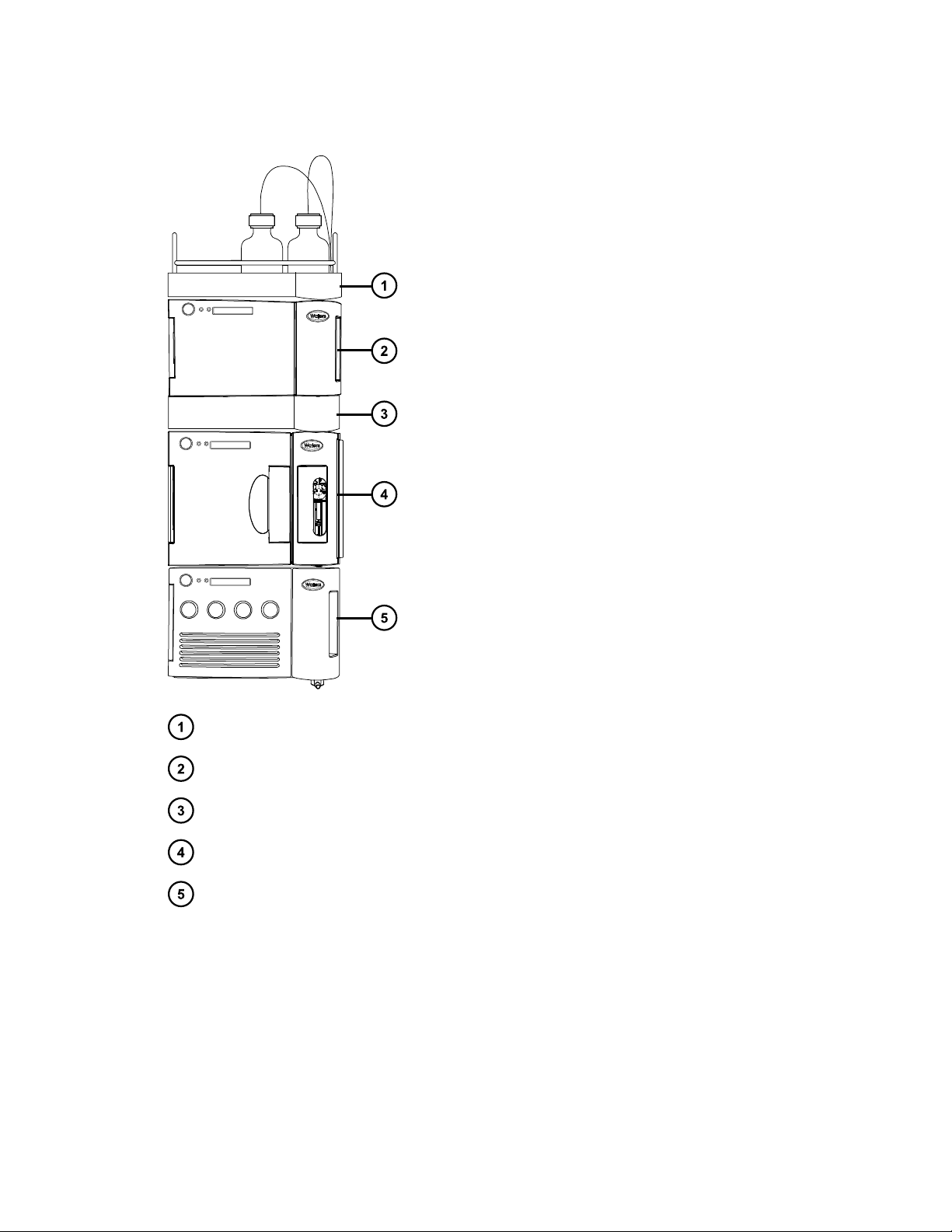
1.3.2 Sample manager-flow through needle.................................................................................20
1.3.3 Column heater .....................................................................................................................21
1.3.4 Column manager (optional) .................................................................................................21
1.3.5 Sample organizer (optional).................................................................................................22
1.3.6 Detection..............................................................................................................................22
1.3.7 Local Console Controller (optional) .....................................................................................23
1.3.8 FlexCart (optional) ...............................................................................................................23
1.3.9 Column technology..............................................................................................................23
1.4 For additional information..............................................................................................................24
2 Performance optimization........................................................................................26
2.1 General guidelines ........................................................................................................................26
2.1.1 Follow these general recommendations when performing a UPLC analysis.......................27
2.2 Dispersion .....................................................................................................................................28
2.3 Carryover ......................................................................................................................................28
2.4 Cycle time (between injections) ....................................................................................................29
2.5 Preventing leaks............................................................................................................................29
2.5.1 Installation recommendations for fittings .............................................................................30
2.6 Developing methods .....................................................................................................................41
2.7 Sample preparation.......................................................................................................................41
2.7.1 Particulates..........................................................................................................................41
2.7.2 Matching sample diluents ....................................................................................................42
2.8 Transferring methods ....................................................................................................................42
2.8.1 Columns calculator .............................................................................................................44
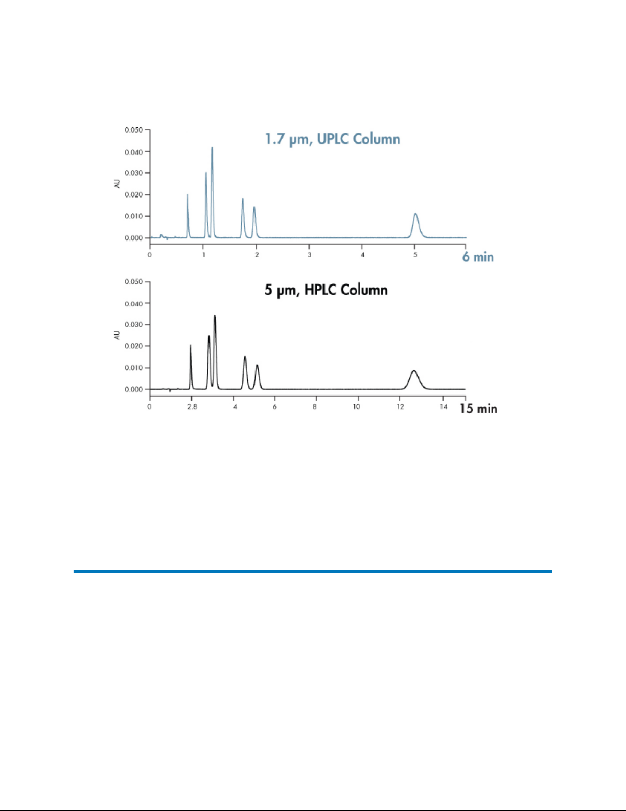
2.8.2 Transferring from HPLC to UPLC........................................................................................44
2.8.3 Transferring from UPLC to HPLC........................................................................................44
3 System preparation ..................................................................................................46
3.1 Powering-on the system................................................................................................................46
3.2 Opening the console .....................................................................................................................47
3.2.1 To open the console from Empower software .....................................................................47
3.2.2 To open the console from MassLynx software ....................................................................47
3.2.3 To open the console from UNIFI software...........................................................................48
3.3 Priming the system........................................................................................................................48
August 8, 2016, 715005049 Rev. C
Page x

3.4 Monitoring module LEDs...............................................................................................................48
3.4.1 Power LED...........................................................................................................................48
3.4.2 Status LEDs.........................................................................................................................48
3.5 Monitoring from control panels......................................................................................................50
3.5.1 Column Manager control panel............................................................................................51
3.5.2 Sample manager control panel............................................................................................52
3.5.3 Solvent manager control panel............................................................................................53
3.5.4 ELS control panel ................................................................................................................54
3.5.5 FLR control panel ................................................................................................................55
3.5.6 PDA control panel................................................................................................................56
3.5.7 RI control panel....................................................................................................................57
3.5.8 TUV control panel................................................................................................................58
3.5.9 2432 conductivity control panel ...........................................................................................59
3.6 Starting up the system ..................................................................................................................60
4 System maintenance................................................................................................63
4.1 Contacting Waters Technical Service ..........................................................................................63
4.1.1 Viewing module information.................................................................................................63
4.2 Maintenance procedures and frequency.......................................................................................64
4.3 Spare parts....................................................................................................................................64
4.4 Troubleshooting with Connections INSIGHT ................................................................................64
4.4.1 To submit a Connections INSIGHT request: .......................................................................65
4.5 Configuring maintenance warnings...............................................................................................65
5 External connections ...............................................................................................66
5.1 Ethernet connections ....................................................................................................................66
5.2 External cable connections ...........................................................................................................67
5.3 Plumbing connections ...................................................................................................................68
5.4 Waste-tubing connections.............................................................................................................69
5.5 Electricity source ...........................................................................................................................70
5.5.1 Connecting to a wall electricity source.................................................................................70
5.5.2 Connecting to a cart's electricity source ..............................................................................71
5.6 Connecting signal cables ..............................................................................................................71
August 8, 2016, 715005049 Rev. C
Page xi

5.7 Connecting to a column module....................................................................................................73
A Safety advisories .....................................................................................................75
A.1 Warning symbols ..........................................................................................................................75
A.1.1 Specific warnings ................................................................................................................76
A.2 Notices..........................................................................................................................................77
A.3 Bottles Prohibited symbol .............................................................................................................77
A.4 Required protection ......................................................................................................................78
A.5 Warnings that apply to all Waters instruments and devices .........................................................78
A.6 Warnings that address the replacing of fuses...............................................................................82
A.7 Electrical symbols .........................................................................................................................84
A.8 Handling symbols .........................................................................................................................85
B Solvent considerations............................................................................................86
B.1 Solvent recommendations ............................................................................................................86
B.2 Recommended solvents ...............................................................................................................87
B.3 Preventing contamination .............................................................................................................87
B.3.1 Clean solvents.....................................................................................................................87
B.3.2 Solvent quality.....................................................................................................................87
B.3.3 Solvent preparation .............................................................................................................87
B.3.4 Water...................................................................................................................................88
B.4 Buffered solvents ..........................................................................................................................88
B.5 Other solvents...............................................................................................................................88
B.6 Hexane/THF compatibility kit ........................................................................................................89
B.7 Additives/modifiers........................................................................................................................89
B.8 Sample diluents ............................................................................................................................89
B.9 Cleaning agents............................................................................................................................90
B.10 Solvents to avoid ........................................................................................................................90
B.11 System recommendations ..........................................................................................................90
August 8, 2016, 715005049 Rev. C
Page xii

B.12 Quaternary solvent manager recommendations.........................................................................91
B.13 Sample manager - flow through needle recommendations ........................................................92
B.14 Common solvent properties........................................................................................................92
B.14.1 Solvent miscibility..............................................................................................................94
B.14.2 Solvent stabilizers .............................................................................................................95
B.14.3 Solvent viscosity................................................................................................................95
B.14.4 Wavelength selection ........................................................................................................96
C Specifications.........................................................................................................101
C.1 System specifications .................................................................................................................101
C.1.1 Instrument control specifications.......................................................................................102
C.1.2 Environmental specifications.............................................................................................103
C.1.3 Electrical specifications.....................................................................................................103
C.1.4 Physical Specifications......................................................................................................104
C.2 Performance specifications ........................................................................................................104
C.2.1 QSM and bioQSM performance specifications .................................................................105
C.2.2 SM-FTN and bioSM-FTN performance specifications ......................................................107
C.2.3 CH-A performance specifications......................................................................................112
C.2.4 CH-30A performance specifications..................................................................................112
C.2.5 30-cm CHC performance specifications............................................................................113
C.2.6 CM-A and CM-Aux performance specifications ................................................................113
C.2.7 Sample organizer performance specifications ..................................................................115
August 8, 2016, 715005049 Rev. C
Page xiii

1ACQUITY UPLC H-Class system
The ACQUITY UPLC H-Class System was designed to support HPLC, UHPLC, and UPLC
methods. The low dispersion of the system allows you to maximize chromatographic resolution
for the most challenging and complex separations. Software and hardware tools enable simplified
transfer of methods and support automated method development.
1.1 UPLC technology
In 2004, Waters made significant advances in instrumentation and column design to introduce
UPLC technology to the field of separation science. By employing this technology, Waters’
ACQUITY UPLC systems achieve a marked increase in resolution, speed and sensitivity in liquid
chromatography when compared to conventional systems.
UPLC technology is based on columns packed with 1.7 µm-diameter, spherical particles coupled
with low dispersion systems, allowing you to realize the full separation potential of these highly
efficient columns.
August 8, 2016, 715005049 Rev. C
Page 14

Figure 1–1: Evolution of particle size in liquid chromatography and the impact on
separation efficiency
It is apparent from the figure, above, that using 1.7-µm particles achieves higher efficiency that
persists as flow rate increases (lower HETP indicates higher efficiency). When operating in this
area of the plot, the peak capacity and the speed of a separation can set limits well beyond those
of conventional HPLC technology.
August 8, 2016, 715005049 Rev. C
Page 15

Figure 1–2: Comparison of chromatographic separations using 5.0-µm and 1.7-µm
particles
The figure above compares two separations, one using HPLC with a column packed with 5 µm
particles, and the other using UPLC with a column packed with 1.7 µm particles. The
improvements in both resolution and the speed of analysis are apparent in the UPLC
chromatogram. Each separation was performed on a 2.1 × 50 mm column. Chromatographic
conditions for the separations were identical, except for the flow rate, which was scaled based on
particle size.
1.2 Features of the ACQUITY UPLC H-Class system
The ACQUITY UPLC H-Class system combines the speed and performance of UPLC with the
ability to run HPLC separations. This combination provides many benefits, including these:
• High-pressure, small-particle chromatography allowing faster, higher-resolution analyses,
compared with conventional HPLC
• Low solvent consumption (significantly less than conventional HPLC)
• Flexibility in solvent mixing by using a quaternary solvent manager
• A flow-through-needle sample manager
August 8, 2016, 715005049 Rev. C
Page 16

• Pump and sample manager design enhancements, to minimize dispersion and reduce cycle
time
• Flexible column management options to support different column lengths and automated
switching of up to 6 columns in independent temperature zones
• An optional sample organizer to expand sample capacity
1.2.1 Software features
1.2.1.1 Quantum Synchronization
Introducing a low-pressure sample into the high-pressure fluid stream during injection causes a
pressure pulse that can affect chromatographic results. The Quantum Synchronization feature
reduces the effect of this pressure pulse. The sample manager and solvent manager
communicate to automatically coordinate the injection sequence, enabling the solvent manager to
provide additional pressure at the exact moment the sample manager switches its injector valve
to the inject position, to introduce the low-pressure sample.
1.2.1.2 Gradient Smart Start
Before each sample injection, a sample manager typically performs wash sequences and then
aspirates the appropriate sample volume. When these tasks are completed, the solvent manager
begins to deliver the gradient to the injection valve. The dwell volume of the system, which affects
the amount of time required for this gradient to reach the column, can be a significant component
of the overall cycle time.
The Gradient Smart Start feature adjusts when an injection is made relative to when it starts. In
this way, when you transfer methods, the feature compensates for differences in dwell volume
between chromatographic systems. Moreover, it automatically coordinates all pre-injection
operations, minimizing delays that would increase the overall cycle time. In doing so, the feature
makes it possible to begin gradient operation before or during the sample manager's pre-injection
functions, resulting in significant time savings.
1.2.1.3 Wash Plungers
Precipitated material that remains on the solvent manager’s pump plungers can damage the high-
pressure seals. The Wash Plungers function washes the seals and plungers with seal wash
solvent, to remove any precipitate. You can use the Wash Plungers function as needed, or run
the function as part of the No-Flow Shutdown feature.
Tip: The Wash Plungers function is not available when the module is operating.
August 8, 2016, 715005049 Rev. C
Page 17

1.2.1.4 No-Flow Shutdown
The No-Flow Shutdown feature runs the Wash Plungers function after the solvent manager
remains idle for a specified time interval. This feature prevents deposition of precipitated material
on the pump plungers and plunger seals while the system is idle.
1.2.1.5 Automatic Prime
When you enable the solvent manager's Automatic Prime function, the system primes the lines of
the optional solvent selection valve when a new line is selected. You can specify the flow rate and
duration of the prime for the new solvent line.
Example: If a first injection uses line D1 and a second injection uses line D2, the solvent
manager primes line D2 between the first and second injections.
1.2.1.6 Flow Ramping
Using the Flow Ramping function, you specify the rate at which the solvent manager increases or
decreases flow.
Tip: The default value is set to support rigid, HPLC and UPLC column particles. For pressure
sensitive columns (such as gel columns), the flow ramping should be adjusted.
1.2.1.7 Auto•Blend Plus
Auto•Blend Plus technology uses pure solvents and concentrated stocks to blend mobile phase
compositions at a specific pH. At the same time, it controls the concentration of salt or organic
solvent, to optimize separations. Use the Auto•Blend Plus feature to create and store buffer
systems in a solvent catalog that all users of an ACQUITY quaternary solvent manager can
share. To prepare and adjust chromatographic mobile phases, you add acid, base, salt or organic
solvent, and water to the solvent reservoirs. By doing so you can, for example, optimize protein
separations, which are especially sensitive to a buffer's pH and salt concentration. You can also
optimize reversed-phase separations that are sensitive to pH and organic-solvent composition.
See also:
•Auto•Blend Plus Technology for Ion Exchange, Size Exclusion, and Reversed-phase
Chromatography
• The Auto•Blend Plus videos on the Support tab on the Waters Auto•Blend Plus page.
1.3 System components
The following illustration depicts a system stack which includes four core modules and the solvent
bottle tray.
August 8, 2016, 715005049 Rev. C
Page 18

Figure 1–3: Example of a system core stack
Solvent bottle tray
Detector
Column heater
Sample manager
Solvent manager
The system includes a solvent manager, sample manager, column heater, detector (tunable
ultraviolet, photodiode array, evaporative light scattering, fluorescent, conductivity, refractive
index, or mass spectrometry), and an ACQUITY UPLC column.
Waters Empower chromatography software, UNIFI, or MassLynx mass spectrometry software
controls the system.
August 8, 2016, 715005049 Rev. C
Page 19

1.3.1 Quaternary solvent manager
The quaternary solvent manager (QSM) is a low-pressure mixing, high-pressure pump. It
provides steady (pulse-free) solvent flow at analytical flow rates to 1 mL/min at 103,421 kPa
(1034 bar, 15,000 psi) and to 2.2 mL/min, at reduced pressures, to 53779 kPa (537 bar, 7800
psi). The QSM can pump four degassed solvents simultaneously using a gradient proportioning
valve (GPV) to dynamically create a specified composition.
Note: An optional 6-solvent selection valve can be added to the QSM line D for increased
solvent flexibility.
1.3.2 Sample manager-flow through needle
The sample manager-flow through needle (SM-FTN) uses a direct-injection mechanism to inject
samples drawn from plates and vials onto a chromatographic column. This injection style injects
all of the aspirated sample onto the column, without any sample volume overhead. The sample
needle is part of the fluidic path and the internal surfaces are flushed by the mobile phase during
the separation. The exterior of the needle is washed in the injection port as specified in the
method. The standard injection volume range of the SM-FTN is 10 µL, however this can be
expanded up to 1 mL through the addition of optional extension loops (installed between the
sample needle and the injection valve).
The SM-FTN also features several advanced sample conditioning features such as dilution, auto-
addition, and mixing, as well as load-ahead capabilities to reduce inject-to-inject cycle times.
1.3.2.1 Wash solvent
The sample manager needle wash system is used to minimize sample carryover. It uses a single
wash solvent and this solvent does not enter the flow path of the system.
Notice:
• Do not leave buffers stored in the system.
• Flush all flow paths, including the needle wash, with plenty of non-buffered solvent
before shutting down the system.
• For extended shutdown periods (longer than 24 hours), use 10% to 20% methanol
in water.
• When using a buffered wash solvent, prime it for a minimum of 30 sec.
• Use of buffers can cause salt build-up on the needle and wash port, which can
require periodic cleaning.
Restriction: Avoid buffered wash solvents.
August 8, 2016, 715005049 Rev. C
Page 20
Other manuals for ACQUITY
1
Table of contents
Other Waters Water System manuals
Popular Water System manuals by other brands

VITA-LIFE
VITA-LIFE AcquaPhi Installation and user guide

BWT
BWT E1 3/4" Series Installation and operating instructions

Kinetico
Kinetico s 2060s withOverdrive owner's manual

Everpure
Everpure Solaria Water Appliance EV9318-40 Specification sheet

Mono
Mono Eco 1-60 Installation, operation and maintenance instructions

Rotek
Rotek RA Series user manual

Armstrong
Armstrong AGE4 Installation and operating instructions

Sidite
Sidite SR882 Installation and operating manual

Hoshizaki
Hoshizaki ROX-10WB3-EW installation manual

Pura
Pura QCUF Installation & operation manual

EINHELL
EINHELL BG-AW 1140 N operating instructions

Clearwater Spas
Clearwater Spas Genesis Blu Fusion manual