AVK A2780 User manual

American AVK Company
An ISO 9001 registered company
Copyright © AVK Group A/S 2019
Maintenance Manual Series 2780
*Subject to change without notice. (rev. 05/19 L)
AVK SERIES 2780 - HIGH PRESSURE,
NOSTALGIC, DRY BARREL HYDRANT
FIELD MAINTENANCE AND
INSTRUCTION MANUAL
TABLE OF CONTENTS
EXPLODED ASSEMBLY / PARTS LIST
INTRODUCTION / DESCRIPTION
RECEIVING AND STORAGE
INSTALLATION AND TESTING
- INSTALLATION
- TESTING
OPERATION AND MAINTENANCE
- HYDRANT TOOLS
- OPERATION
- MAINTENANCE PROCEDURES
- LUBRICATION
- INSPECTION
- DISASSEMBLY FOR INSPECTION
- REASSEMBLY AFTER INSPECTION
REPAIR PROCEDURES
- TRAFFIC REPAIR KIT
OPTIONAL EQUIPMENT
- EXTENSION KITS
- TAMPERGUARD WEATHERSHIELD
- THRUST BEARING OPERATING ASSY.
TROUBLESHOOTING GUIDE
PARTS AND SERVICE
WARRANTY
AMERICAN AVK COMPANY

page 1
American AVK Series 2780 Nostalgic Hydrant
Exploded Parts Breakdown
F1
F2
F5
F6
F7
F8
F9
F10
F8
F12
F13
F14
F15
F16
F17
F13
F18
F19
F23
F25
F26
F27
F30
F31
F32
F31
F34
F38
F3
F4
F11
F75
F55
F44
F31
F20
F21
F55
F22
F28
F29
F88
F34
F31
F33
F36
F37
F41
F17
F49
F46
F32
F53
F51
F53
F17
F54
F38
F61
F50
F67
F94
F60
F95
F55
F56
As of Dec. 2018, the upper Anti
Friction Washer has been replaced
with a 3 piece roller bearing assembly

page 2
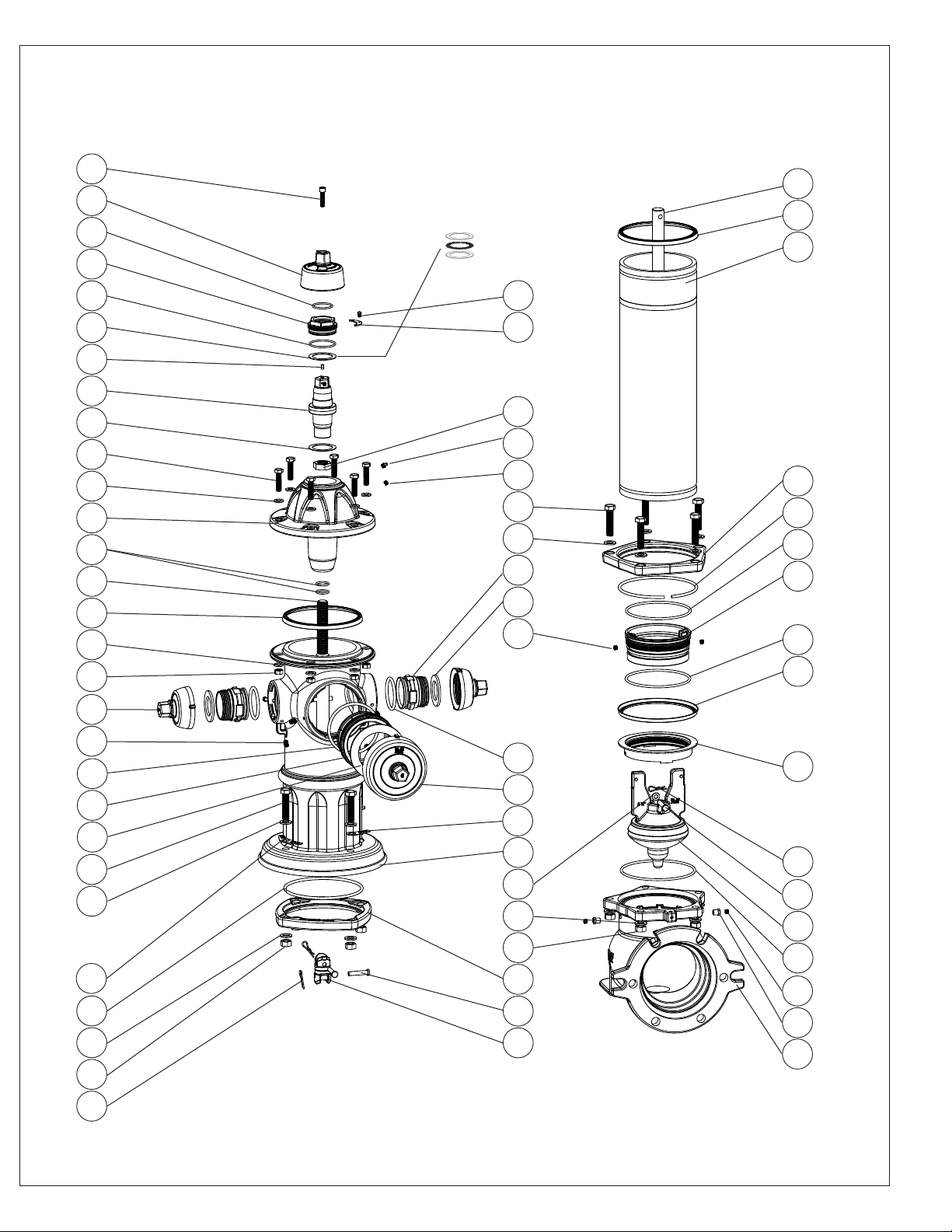
Item No. Description Material
F1 Weathershield Bolt 304 Stainless steel
F2 Weathershield Grey Iron, ASTM126, Class “B”
F3 Lockplate Bolt 304 Stainless steel
F4 Lock Plate 304 Stainless steel
F5 Inner Thrust Nut O-ring NBR
F6 Thrust Nut Copper Alloy
F7 Outer Thrust Nut O-ring NBR
F8 Anti Friction Washer Nylon
F9 Lubrication Hole Seal NBR
F10 Operating Nut Copper Alloy
F11 Stop Nut Zinc plated steel
F12 Bonnet Bolt Zinc plate, 304, 316 Stainless steel
F13 Bonnet Washer Zinc plate, 304, 316 Stainless steel
F14 Bonnet Ductile Iron, ASTM A536
F15 Stem Seal O-rings NBR
F16 Upper Stem Rod 304 Stainless steel, Epoxy coated steel
F17 Barrel Gasket NBR with stainless steel insert
F18 Bonnet Nut Zinc plate, 304, 316 Stainless steel
F19 Hose Nozzle Cap Grey Iron, ASTM126, Class “B”
F20 Hose Nozzle Copper Alloy
F21 Hose Nozzle Cap Gasket NBR
F22 Hose Nozzle O-ring NBR
F23** Set Screw - (Nozzle) 304 Stainless steel
F24* Chain Assembly Zinc Plated Steel
F25 Pumper Nozzle O-ring NBR
F26 Pumper Nozzle Copper Alloy
F27 Pumper Cap Gasket NBR
F28 Pumper Cap Grey Iron, ASTM126, Class “B”
F29 Nozzle Section Ductile Iron, ASTM A536
F30 Nozzle Section Bolt Zinc plate, 304, 316 Stainless steel
F31 Nozzle Section Washer 304 Stainless steel
F32 Lock Ring 304 Stainless steel
F33 Breakable Flange Ductile Iron, ASTM A536
F34 Nozzle Section Nut 304 Stainless steel
F35* Upper Barrel Ductile Iron, ASTM A536
F36 Coupler Pin 420 Stainless steel
F37 Breakable Stem Rod Coupling 431 Stainless steel
F38 Spring Pin 304 Stainless steel
F41 Lower Stem Rod Mild Steel, 304 Stainless steel
F42* Extension Coupling 304 Stainless steel
F43* Extension Barrel Ductile Iron, ASTM A536
F44 Upper.Extension Barrel Bolt Zinc plate, 304, 316 Stainless steel
F45 N/A
F46 Standpipe Flange Ductile Iron, ASTM A536
F47* Monitor Elbow Ductile Iron, ASTM A536
F48* Extension Stem Rod Mild Steel, 304 Stainless steel
F49 Lower Barrel Ductile Iron, ASTM A536
F50 Lower Barrel O-ring NBR
F51 Valve Seat Ring Copper Alloy
F52 N/A
F53 Valve Seat O-ring NBR
F54 Drain Ring Copper Alloy
F55 Brass Plug Copper Alloy
F56 Brass Fitting Copper Alloy
F58 N/A
F60 Main Valve Retaining Pin 420 Stainless steel
F61 Main Valve EPDM, Encapsulated Ductile Iron
F62 Base Gasket NBR
F63* Straight Inlet Ductile Iron, ASTM A536
F65 N/A
F66 N/A
F67 Base Ductile Iron, ASTM A536
F68 N/A
F69*** Thrust Bearing Race Hardened Steel
F70*** Thrust Bearing Hardened Steel
F71* Modern Nozzle Section Bolt Zinc plate, 304, 316 Stainless steel
F72* Base Gasket - Specify type NBR
F73* Storz Cap O-ring EPDM
F74* Cap/Cable Assembly
F75 Zerk Fitting Case Hardened Steel, Zinc Plated
F88 Main Valve Retaining Pin Washer 304 Stainless steel
F90* Hose Nozzle Position Clip 300 Series Stainless
F91* Pumper Nozzle Position Clip 300 Series Stainless
F92* Inner Storz Cap O-ring NBR
F93* Storz Adaptor Copper Alloy
F94 Bury Tag Aluminum
F95 Extension Bury Tag Aluminum
* Not Shown in Exploded Parts Breakdown
** As of July 2015, secondary Set Screws were added to
all dry barrel nozzle outlets
*** As of Dec. 2018, the upper Anti Friction Washer has been
replaced with a 3 piece roller bearing assembly comprised of 2,
F69 Thrust Bearing Races and 1, F70 Thrust Bearing.

page 3
INTRODUCTION / DESCRIPTION
The American AVK Series 2780 Nostalgic Hydrant is designed to be a trouble free, easy to maintain hydrant. This
manual will provide you with the information needed to properly install and maintain the re hydrant and to ensure a long
service life. Features of the American AVK Series 2780 Nostalgic Hydrant include an EPDM encapsulated one piece main
valve and a stainless steel upper stem. The series 2780 is rated for a working pressure of 250 psi, is UL, ULC listed and FM
approved, and meets or exceeds the requirements of AWWA C502, Standard for Dry Barrel Fire Hydrants, (where applicable).
The AVK Series 2780 hydrant and hydrant tools are designed so that one person can perform all repairs and maintenance
outlined in this manual.
RECEIVING AND STORAGE
Inspect the hydrants upon receipt for damage in shipment. Note any damage on the bill of lading and have the driver
sign it. Notify American AVK. Unload all of the hydrants carefully to avoid damage. Verify that the hydrants have the correct
direction to open, the correct nozzle conguration and threads, the correct operating nut size and shape, the correct depth
of bury, and the correct inlet connection. Hydrants should remain clean and dry, and the main valve should be closed until
installed to prevent weather related damage. For long term storage the hydrants should be stored indoors.
INSTALLATION AND TESTING
NOTE: American AVK recommends AWWA Standard C600 and AWWA Manual M17 for further information
regarding hydrant installation and testing.
WARNING: All water lines must be isolated or depressurized and drained before installing or maintaining re
hydrants. Failure to do so may cause pressure to be released resulting in severe injury or death.
INSTALLATION
Correct installation of the Series 2780 Nostalgic Hydrant is important for proper operation. The following steps are
general installation guidelines for a standard AVK Series 2780 re hydrant. Local conditions may require variations.
1. Before installing a hydrant, check to make sure all bolts are tight and all nozzles are properly installed (See
NOZZLE INSTALLATION). Clean any dirt and debris from inside the hydrant base and from the hydrant lead.
2. All hydrants shall be installed as plumb as possible.
3. Consult local codes and standard for hydrant placement. In general, the following guidelines should be observed. Locate
hydrants to provide complete accessibility while minimizing the possibility of damage from vehicles or injury to
pedestrians. The hydrant should be placed so that no part of the hydrant is closer than two feet to the curb. Make sure
the pumper nozzle faces the street for easy connection. The centerline of the hydrant nozzles should be no less than
18-inches above the ground to allow for attachment of hoses and to operate the hydrant wrench.
4. Always install auxiliary gate valve in the lateral between the hydrant and the main to permit inspection and repair of the
hydrant.
5. On trafc hydrants, be sure the earth is rmly compacted around the barrel to support the lower barrel against side
loading. If the soil is too sandy and will not support the loads, pour a concrete pad around the barrel at or near the bury
line at least 6 inches thick and 24 inches in diameter to support the barrel.
6. Place clean coarse gravel or crushed stone from the bottom of the trench to at least 6 inches above the drain opening in
the hydrant and to a distance of 1 foot around the elbow to provide drainage. For clay or other impervious soils,
excavate a drainage sump 2 feet in diameter and 3 feet deep below each hydrant. Fill the sump with clean coarse gravel
or crushed stone to a level 6 inches above the drain opening. Place a plastic sheet over the gravel to prevent dirt from
clogging the drains.
7. Restrain hydrant movement with appropriate thrust blocking or restrained joint to prevent pipe joint separation.
8. When rst installed, the hydrant should be operated from full closed to full open position and back to make sure no
obstructions are present.
9. After the line and hydrant have been hydrostatically tested, the hydrant should be ushed and then checked for proper
drainage.
10. AWWA Manual M17 has further guidelines to assist with hydrant installation

page 4
Fig. 1
Hydrant Installation
Concrete
thrust block Concrete
Curb
Concrete collar for protection of trafc
model hydrants.
Drain Detail:
Caution: When pouring
thrust block, do not cover
drain holes.
1/3 cubic yard drain eld
rock.
Concrete
thrust block
Supply Valve
6"
2' min.
2'
Bury
Concrete
Grounding from hydrant base to Zinc
Anode for providing cathodic
protection. Effective, April 2015.
(Anode & grounding wire not supplied.)

page 5
PRESSURE TESTING
American AVK Recommended Hydrant Testing Procedure
AAVK recommends that AWWA M17, "Installation, Field Testing, and Maintenance of Fire Hydrants", chapters 4.3 and 4.4
be followed for field testing and placing the hydrant in service. The following is excerpted from AWWA M17 for the
reader's convenience:
PRESSURE TEST AT MAIN PRESSURE
1. Ensure that all nozzles are properly installed per section “NOZZLE INSPECTION & REPLACEMENT”
2. Remove the highest outlet-nozzle cap and open the hydrant valve a few turns. Allow water to reach the bottom of the
outlet nozzle. (If the hydrant is furnished with a tapped-plug air vent, then it is not necessary to remove the nozzle cap.
Just open the air vent.)
3. Replace the outlet-nozzle cap and leave it loose to permit all air to escape, or close the tapped-plug air vent.
4. After all air has escaped, tighten the outlet-nozzle cap.
5. Open the hydrant completely. (Opening the hydrant fully before all air has escaped will compress the air and cause a
safety hazard.) (AAVK comment: underlined as very important)
6. Check for leakage at flanges, outlet nozzles, and the packing or O-rings around the stem.
7. If leakage is noted, repair or replace the faulty components or the entire hydrant. (AAVK comment: only after hydrant
is closed and all pressure is bled off.)
8. Repeat the test until results are satisfactory.
PRESSURE TEST AT PRESSURES ABOVE MAIN PRESSURE
1. Connect a pressure-test pump to one of the hydrant's outlet nozzles.
2. Open the highest outlet-nozzle cap. Open the hydrant valve a few turns. Allow the hydrant to fill until water is at the
bottom of the outlet nozzle.
3. After all air has escaped, tighten the outlet-nozzle cap.
4. Open the hydrant completely.
5. Close the auxiliary valve.
6. Pump up to test pressure (usually 150 psi [1034 kPa]).
7. Check for leakage at flanges, outlet nozzles, and the packing or O-rings around the stem.
DRAINAGE TEST
1. Remove one of the Hose Caps (F19) and ll the hydrant with water.
2. With the hydrant in the closed position, place the palm of one hand over the open Hose Nozzle (F20). As the water drains
from the hydrant it should create a noticeable vacuum indicating proper drainage.
3. For further instructions refer to the AWWA M-17 Hydrant Manual, Chapter 4.3.
EXTERNAL DRAIN PLUGGING
American AVK offers the option of External or Internal Drain Facility Plugging.
1. Prior to installation, for external plugging, visually verify for factory installed plugs or screw two Brass Plugs (F55) into the
Brass Fittings (F56) located on the Main Valve Flange (F57) using a 3/16” hexagon key.
INTERNAL DRAIN PLUGGING
1. For internal plugging, refer to the warnings and steps in the "MAIN VALVE INSPECTION" section on page 14.
2. After removing the main valve assembly, screw in two Brass Plugs (F55) into the Valve Seat Ring (F51) using a 3/16”
hexagon key.( Fig. 2)
3. Inspect the main valve assembly prior to re-installation. Replace any damaged items and follow the steps in the "MAIN
VALVE REREASSEMBLY" section on page 15 .

page 6
Fig. 2
Internal Drain Plugging
F55
F51

page 7
AVK Seat Wrench
27-150-30-100
AVK Operating Wrench
27-150-30-700
OPERATION AND MAINTENANCE
HYDRANT TOOLS
American AVK offers a standard toll kit for routine maintenance requirements. The kit is comprised of the following AVK
specic tools.
1. AVK Seat Wrench: Part Number: 27-150-30-100
For use in removal and replacement of the MAIN VALVE/ SEAT
ASSEMBLY. One of the major benets of the AVK design is that only one
universal wrench is required regardless of bury depth.
2. AVK Oilsaver Adapter Part Number: 27-150-30-300
3. AVK Operating Wrench Part Number: 27-150-30-700
4. AVK Seat Wrench Alignment Tool Part Number: 27-150-30-500
METRIC AND INCH WRENCH REQUIREMENTS FOR AMERICAN AVK HYDRANTS
PART INCH SIZE METRIC SIZE
Weathershield Retaining Bolt (Allen) 5/16” 8mm
Thrust Nut Retaining Screw (Allen) 5/32” 4mm
Nozzle Retaining Screw (Allen) 3/16” 5mm
Bonnet Bolts and Nuts 3/4” 19mm
All other Bolts and Nuts 15/16” 24mm
AVK Oilsaver
27-150-30-300
AVK Seat Wrench
Alignment Tool
27-150-30-500
Main Valve removal end
Stop Nut removal end

page 8
OPERATION AND MAINTENANCE
OPERATION
The American AVK Series 2780 Nostalgic Hydrant is designed to be an easily operated, low torque, high ow re hydrant.
It will not require excessively high loads to operate. It is possible to damage the hydrant by forcing it beyond its normal
operational limits.
The thrust bearing hydrant requires a minimum of torque to operate. It is possible to damage the hydrant by forcing it
beyond its limits of travel with excess torque; therefore:
1. Check direction of opening as marked on the hydrant Weathershield (F2).
2. To open, turn the Operating Nut (F10), in the opening direction, indicated by an arrow on the Weathershield (F2), until
the Main Valve (F61), is fully open. (Approximately 19 to 21 turns) The Stop Nut (F11), should prevent the hydrant from
opening beyond the fully open position. Do not force the hydrant in the opening direction beyond full open as
indicated by sudden resistance to turning. If water does not ow when the hydrant is open, it is probably due to a closed
valve upstream from the hydrant.
3. To close, turn the operating nut until the Main Valve stops off the ow. It is not necessary to close this style of hydrant with
great force. Once the ow has stopped, loosen the operating nut in the opening direction, 1/2 to 1 turn to take the strain off
the operating parts of the hydrant and to make it easier to open the hydrant.
F2, Weathershield
Note: Open Left shown.
(F11), Stop Nut resting against
internal lubrication reservoir in
the Bonnet (F14).
F14
F11
Fig. 3
Operation
F10

F1
F55
page 9
MAINTENANCE PROCEDURES
The American AVK Series 2780 Dry Barrel Hydrant is designed
to be a trouble free, easy to maintain hydrant. The following steps
are recommended to provide trouble free operation.
GREASE LUBRICATION (Fig. 4A)
WARNING: On a partially disassembled hydrant under line
pressure, pressing down on the stem could force open the Main
Valve (F61) and allow it to slam shut, creating a water hammer.
To prevent this during routine maintenance, rst locate and be
sure the supply valve is closed. Relieve the pressure on the
Main Valve (F61) by momentarily opening and then closing the
hydrant. Reopen the supply valve after the hydrant has been
reassembled.
GREASE SERVICING FOR BONNETS WITH ZERK FITTINGS,
(Fig. 4A)
CAUTION: For grease servicing, ensure that the Weathershield
bolt has been loosened to prevent damage to the internal
O-rings.
1. Relling is performed by loosening the Weathershield bolt
(F1) with a 5/16” or (8mm) hexagon key.
2. Rell lubricant reservoir with a food grade grease using a
Grease gun on the Zerk Fitting (F75).
3. Tighten the Weathershield Bolt.
OIL LUBRICATION (Fig. 5A)
WARNING: On a partially disassembled hydrant under line
pressure, pressing down on the stem could force open the Main
Valve (F61) and allow it to slam shut, creating a water hammer.
To prevent this during routine maintenance, rst locate and be
sure the supply valve is closed. Relieve the pressure on the
Main Valve (F61) by momentarily opening and then closing the
hydrant. Reopen the supply valve after the hydrant has been
reassembled.
OIL SERVICING FOR BONNETS WITH BRASS PLUG,
FIGURE 5A
1. Loosen the Weathershield bolt (F1) with a or 5/16”,(8mm)
hexagon key. This will allow the oil reservoir to breath and be
lled faster.
2. Remove the Brass Plug (F55) with a 3/16” hexagon key.
Rell the oil reservoir with FDA approved food grade oil.
3. Install the Brass Plug and tighten the Weathershield Bolt.
This should be done after any repairs or as required by local
specications.
Fig. 4A
Grease lubrication for bonnets
with zerk ttings
F1
F75
Fig. 5A
Oil lubrication for bonnets
with brass plug

page 10
INSPECTION
NOZZLE DISASSEMBLY FOR INSPECTION: FIGURES 6A-6J
If inspection of the re hydrant is required, follow the DISASSEMBLY FOR INSPECTION instructions.
WARNING: For all of the following repair procedures, the hydrant must be isolated or the system depressurized and
drained before removing the hydrant components. Failure to do so may cause pressure to be released resulting in severe
injury or death.
NOZZLE INSPECTION
NOTE: If the hydrant is leaking from any of the nozzles, rst try to determine if they are leaking from the Hose Cap Gasket
(F21), or the Hose Nozzle O-ring (F22), and perform the applicable seal replacement procedure for the nozzle(s) in question.
NOTE: As of July, 2015, American AVK series 27 dry barrel hydrants have a secondary Nozzle Retaining Screw (F23),
installed on every outlet. All Nozzle Retaining Screws are concealed and painted over at the factory.
WARNING: Hydrants with secondary Nozzle Retaining Screws that are exposed should be carfully inspected prior to use
as this may indicate that the hydrant outlets have been tampered with.
Proper Nozzle Alignment:
1. Remove the Hose Nozzle Cap (F19), or Pumper Nozzle Cap (F28), using an AVK Hydrant Wrench or adjustable hydrant
wrench.
2. Locate the Nozzle Retaining Screw (F23) holes. They are located approximately ½", in from the edge of the nozzle section
and at about the 4:30 to 8:30 positions when facing the nozzle. Remove the putty/foil concealing the screws.
3. If the retaining screw is missing, ensure that the nozzle is correctly installed as shown in g. “6G”,(for Hose Nozzles),
"6J", (for Pumper Nozzles), then immediately replace it (F23 - Nozzle Retaining Screw, M10mm x 16mm, 304 stainless
steel).
4. For Hose Nozzles (F20), there should be a small "dimple" or punch mark on the hose nozzle. This mark should be in
alignment with the Nozzle Retaining Screw (F23) as shown in gure “6G”.
5. For Pumper Nozzles, the “dimple” or punch mark is on the face of the cap end of the pumper nozzle as shown in gure
“6J”.
6. If the dimple is not in alignment with the retaining screw (F23), remove the retaining screw and rotate the nozzle until the
alignment is correct.
7. Apply a drop of thread-locker (Loctite #242 or equal) to the end of the retaining screw, tighten it until it just contacts the
nozzle, do not back off the locking screw.
8. Replace the hose nozzle cap (F19).
9. If required, repeat steps 1 through 8 for the other nozzles.
AVK hydrants manufactured before 2005 may not have the position marks ("dimples" or punch marks) on the hose and
pumper nozzles. In this case, follow the following steps to add the indicators to ensure correct nozzle positioning:
1. Remove the hydrant nozzle caps.
2. Using a 3/16" or 5mm Allen wrench, remove the Nozzle Retaining Screws (F23).
3. Rotate the nozzles in a clockwise direction approximately 40 degrees until the nozzle slot aligns with lug opening on the
nozzle section, located at the 6 o'clock position. See Fig. "6F".
4. Pull the cap/nozzle assembly outward until the nozzle lugs are between the nozzle section lugs as shown in Fig. "6C".
5. Loosen the cap, then nish removing the cap/nozzle assembly.
NOTE: AVK hydrants manufactured after 2004 have a "fth lug" located at the 6 o'clock position in the outlets. This prevents
the nozzles from being installed with the slotted lug in the wrong location.
6. Using a pointed punch and a hammer, stamp a small dimple into the surface of the nozzles as shown in gures “6F &
6J”. The small dimple must be located on the center line of the "split" lug on the bronze nozzles.
7. Mark the dimples with a permanent ink marker to make the marks easily visible.
8. Follow the steps in "REASSEMBLY AFTER INSPECTION", to reinstall the nozzles and caps.

page 11
INSPECTION
NOZZLE DISASSEMBLY FOR INSPECTION (continued):
WARNING: For all of the following repair procedures, the hydrant must be isolated or the system depressurized and
drained before removing the hydrant components. Failure to do so may cause pressure to be released resulting in severe
injury or death.
Nozzle leaking from around the Nozzle Cap:
1. Remove the Hose Nozzle Cap (F19), or Pumper Nozzle Cap (F28), using an AVK Hydrant Wrench or adjustable hydrant
wrench.
2. Remove and replace the Hose Nozzle Cap Gasket (F22), or Pumper Nozzle Cap Gasket (F27), and replace the cap and
gasket assembly.
Nozzle leaking from around the Nozzle O-ring area:
1. Remove the Nozzle Retaining Screws (F23) using a 3/16" or 5mm Allen wrench.
2. Rotate the nozzle in a clockwise direction approximately 40 degrees until the nozzle slot aligns with lug opening on the
nozzle section, located at the 6 o'clock position of the desired outlet. See Fig. "6F".
3. Pull the cap/nozzle assembly outward until the nozzle lugs are between the nozzle section lugs as shown in Fig. "6C".
4. Loosen the cap, then nish removing the cap/nozzle assembly. (See Fig. 6E)
5. Remove the old Hose Nozzle O-ring (F22), or Pumper Nozzle O-ring (F25), and replace with a new one.
6. Lightly grease the o-ring with a food grade grease that contains no acetate or silicone.
7. Follow the steps in "REASSEMBLY AFTER INSPECTION", to reinstall the nozzles and caps.
NOZZLE REASSEMBLY AFTER INSPECTION:
1. Insert the greased Cap/Nozzle assembly into the nozzle section outlet until the nozzle lugs are in line with the nozzle
section lugs as shown in Fig. 6C.
2. Tighten the cap on the nozzle. Insert the cap/nozzle assembly fully into the nozzle section and using a hydrant wrench,
slowly rotate the cap/nozzle assembly counter clockwise, approximately 40 degrees, until the slotted nozzle lug aligns
with the Nozzle Retaining Screw hole. This can be veried by lining up the dimple with the Nozzle Retaining Screw hole.
3. Apply a drop of thread-locker (Loctite #242 or equal) to the end of the retaining screws, and using a 3/16" or 5mm Allen
wrench, tighten it until it just contacts the nozzle, do not back off the locking screws.
4. Verify that the Cap has been secured.
5. Once the hydrant has been completely reassembled, turn on the supply valve and slowly open the hydrant to check for
leaks.

page 12
A
DETAIL A
SCALE 1 : 5
F19
F21
F20
F22
F23
Fig. 6A Fig. 6B Fig. 6C
Fig. 6D Fig. 6E Fig. 6F
Fig. 6G Fig. 6H Fig. 6J
F28
F27
F26
F25
Dimple
Dimple Dimple
F23 F23
Nozzle lug
rotated between
nozzle section
lugs to allow
cap removal.
Fifth Lug
Fifth Lug
Secondary set screw
Secondary set screw
Secondary set screw

page 13
DISASSEMBLY FOR INSPECTION: (continued)
MAIN VALVE INSPECTION
WARNING: For all of the following repair procedures, the hydrant must be isolated or the system depressurized and drained
before removing the hydrant components. Failure to do so may cause pressure to be released resulting in
severe injury or death.
AVK Hydrants are designed to allow all internal components to be easily removed without displacing installation.
WARNING: On a partially disassembled hydrant under line pressure, pressing down on the stem could force open the
Main Valve (F61) and allow it to slam shut, creating a water hammer. If the intention is to remove the Main
Valve (F61) rst locate and be sure the supply valve is closed. Relieve the pressure on the Main Valve (F61) by
momentarily opening and then closing the hydrant. Reopen the supply valve after the hydrant has been
reassembled.
1. Remove the Weathershield Bolt (F1) with a 5/16",(8mm) hexagon key. Lift off the Weathershield (F2). (See Fig. 7A)
2. Remove the Lock Plate Screw (F3) and Lock Plate (F4) with a 5/32" or (4mm), hexagon key.
3. Using the AVK operating wrench, or a large adjustable wrench, unscrew the Thrust Nut (F6) counterclockwise. (See Fig.
7A &7B)
4. Remove the Operating Nut (F10) using the AVK operating wrench. Turn counterclockwise for "Open Left Hydrants", and
clockwise for "Open Right", hydrants. Remove the Anti Friction Washers (F8), and set aside with the Operating Nut.
(See Fig. 7C)
5. Remove the Stop Nut (F11) with the deep socket located at the end of the AVK seat wrench. CAUTION: Do not
overtighten the Stop Nut (F11), during re-assembly! (See Fig. 7D)
6. Remove the six Bonnet Bolts (F12) and associated hardware using 3/4" or 19mm wrenches. Lift Bonnet (F14) over the
Upper Stem Rod (F16) and set aside.
NOTE: On oil lled hydrants, to avoid draining of oil from the oil reservoir in the bonnet (F14), press the Oilsaver sleeve
(See Fig. 7E and 7F), with the stop ring placed downward) over the Upper Stem Rod (F16) during the disassembly.
While holding the Oilsaver in place, lift the Bonnet (F14), and Oilsaver off of the Upper Stem Rod (F16). During
reassembly inspect the Stem Seal O-rings (F15) and the Barrel Gasket (F17) for damage.
7. To remove the Valve Seat Ring (F51) and Main Valve Assembly, Slide the AVK Seat Wrench ( Fig. 7G) over the Upper
Stem Rod (F16) and engage the seat removal pin. Turn the tool counterclockwise, (approximately 6 turns) until the Valve
Seat Ring has disengaged from the Drain Ring (F54).
NOTE: For deeper buries, and optional AVK Seat Wrench Alignment Tool is available. (See Fig. 7G)
8. Remove tool and set aside. Lift and remove the Upper Stem Rod / Lower Stem Rod and Main Valve Assembly from the
Lower Barrel (F49). (See Fig. 7H)
9. Inspect the Main Valve (F61), Valve Seat Ring (F51), Valve Seat O-rings (F53) for damage. Replace if necessary.
10. If any of the above parts are to be replaced, clamp the Lower Stem Rod (F41) in a standard pipe vise. (See Fig. 7J)
Slide the Valve Seat Ring (F51) off the ears of the Main Valve. To disconnect the Main Valve from the Lower Stem Rod
(F41) remove the Spring Pin (F38), and Main Valve Retaining Pin Washer (F88), from the Main Valve Retaining Pin (F60).
Reverse the steps for reassembly. Lightly grease the Main Valve ears and Main Valve O-rings (F53), with a food grade
grease that contains no acetate or silicone.

page 14
REASSEMBLY AFTER INSPECTION:
MAIN VALVE REASSEMBLY
CAUTION: Take care not to cross thread the Seat Ring (F51), during reassembly.
1. Using the AVK Seat Wrench, re-install the Main Valve and Stem assembly. Using the seat wrench, rotate the main valve
and stem assembly counter clockwise until you feel a slight drop. Then tighten clockwise until the Main Valve/Stem
assembly is completely tightened. Take care not to over tighten the assembly!
2. Verify that the Barrel Gasket (F17), is in place on top of the Nozzle Section. (See Fig. 7F) Carefully slide the Bonnet
(F14), over the Upper Stem Rod (F16), taking care not to dislodge the Stem Seal O-rings (F15), or Barrel Gasket.
Carefully rotate the bonnet until the grease zerk or oil, brass plug is in the desired positioning.
3. Install the Bonnet Bolts, Washers, and Nuts nger tight.
4. Using the AVK Seat Wrench, install the Stop Nut (F11). Do not over tighten the Stop Nut!
5. If required, ll the lubrication reservoir with the appropriate food grade oil or grease that contains no acetate or silicone.
6. Place one Anti Friction Washer (F8), on the top and bottom of the Operating Nut (F10) thrust collar. (See Fig. 7A)
7. Install the Operating Nut and Anti Friction Washers. Tighten the operating nut until the thrust collar just snugs up against
the hydrant bonnet.
8. Lightly grease the o-rings on the Thrust Nut (F6), and screw the Thrust Nut into the Bonnet completely, then back off the
Thrust Nut 1/8 to 1/4 turn, until the Thrust Nut lines up with the Lockplate (F4).
9. Install the Lockplate and secure it with the Lockplate Screw (F3), using a 7/64" or (3mm), hexagon key.
10. Tighten the Bonnet Bolts/Nuts to 65 Ft. Lbs..
11. Install the Weathershield and Weathershield Bolt using a 5/16",(8mm) hexagon key.
12. After reassembly is complete, open the supply valve and test the hydrant for leaks.

page 15
F1
F2
Fig. 7A Fig. 7B Fig. 7C
Fig. 7D Fig. 7E Fig. 7F
Fig. 7G Fig. 7H Fig.7J
F3
F4
F8
F10
F11
F6
Oil Saver
AVK Seat
Wrench
F16
AVK
HydrantWrench
F41
F38
F51
F88
F60
F53
F61
F17
F15
AVK Seat Wrench
Alignment Tool

page 16
REPAIR PROCEDURES
TRAFFIC REPAIR:
WARNING: For all of the following repair procedures, the
hydrant must be isolated or the system depressurized and
drained before removing the hydrant components. Failure
to do so may cause pressure to be released resulting in
severe injury or death.
AVK Dry Barrel Hydrants feature a safety Breakable Flange
(F33) and Breakable Stem Rod Coupling (F37) design. This
allows the hydrant head assembly to be struck by a vehicle
and “Break Away” reducing the impact to the water main. In
the event the hydrant head assembly has been broken away,
the following repairs will be necessary.
WARNING: On a partially disassembled hydrant under
line pressure, pressing down on the stem could force open
the Main Valve (F61) and allow it to slam shut, creating a
water hammer. In the event of a vehicle collision or break
away, locate and be sure the supply valve is closed. After
reassembly, relieve the pressure on the Main Valve (F61) by
momentarily opening and then closing the hydrant. Reopen
the supply valve after the hydrant has been reassembled.
1. Remove the hardware (F30,31,34) from the Breakable
Flange (F33). Slide the Lock Ring (F32) off of the Lower
Barrel (F49). (See Fig. 8)
2. Remove the Spring Pins (F38) from the Coupler Pins
(F36) in the Upper Stem Rod (F16) and Lower Stem Rod
(F41). Remove and discard the broken Breakable
Coupling (F37).
3. If required, remove the Upper Stem Rod (F16) from the
hydrant head assembly by following the Warnings and
steps 1 through 4 in the MAIN VALVE INSPECTION
section on page 14.
4. Re-connect the Upper Stem Rod (F16) to the Lower Stem
Rod (F41) with new Coupler Pins (F36), new Breakable
Stem Rod Coupling (F37), and secure with Spring Pins
(F38).
NOTE:For hydrants manufactured prior to Sept. 7, 2010,
the Breakable Stem Rod Coupling should replaced with the
arrow pointing up. For hydrants manufactured after Sept. 7,
2010, there is no orientaion. (See Fig. 9)
5. Slide a new Breakable Flange (F33) over the Lower
Barrel (F49), then install a new Lock Ring (F32) into the
groove on the Lower Barrel..
WARNING: Be sure the Breakable Flange(F33) is right side
up, indicated with the text "This Side Up", facing towards the
nozzle section. (See Fig.8&9) .
6. Clean the hydrant’s Nozzle Section/Upper Barrel and
Lower Barrel ange face and install a new Barrel Gasket
(F17).
Fig. 8
Trafc Repair
F31
F34
F32
F30
F49
F17
F33
F37
F38
F36
F41
F16

page 17
REPAIR PROCEDURES
TRAFFIC REPAIR: (continued)
7. Lift the hydrant nozzle section assembly (F29) over the Upper Stem Rod (F16) and carefully place the assembly on the
Lower Barrel and Barrel Gasket (F17). Check for correct alignment of the Barrel Gasket (F17) and re-install the nozzle
section mounting hardware. Torque the mounting hardware (F30,F31,F34) to 80 foot pounds.
8. Verify that the Barrel Gasket (F17), is in place on top of the Nozzle Section. (See Fig. 7F) Carefully slide the Bonnet
(F14), over the Upper Stem Rod (F16), taking care not to dislodge the Stem Seal O-rings (F15), or Barrel Gasket (F17).
9. Install the Bonnet Bolts, Washers, and Nuts Finger tight.
10. Using the AVK Seat Wrench, install the Stop Nut (F11). Do not over tighten the Stop Nut! Fill the lubrication reservoir
with the appropriate food grade oil or grease that contains no acetate or silicone.
11. Place one Anti Friction Washer (F8), on the top and bottom of the Operating Nut (F10) thrust collar. (See Fig. 7A)
12. Install the Operating Nut and Anti Friction Washers.
13. Lightly grease the o-rings on the Thrust Nut (F6), and screw the Thrust Nut into the Bonnet completely, then back off the
Thrust Nut 1/8 to 1/4 turn, until the Thrust Nut lines up with the Lockplate (F4).
14. Install the Lockplate and secure it with the Lockplate Screw (F3), using a 7/64" or (3mm), hexagon key.
15. Tighten the Bonnet Bolts/Nuts to 65 Ft. Lbs.
16. Install the Weathershield and Weathershield Bolt using a 5/16",(8mm) hexagon key.
17. After reassembly is complete, open the supply valve and test the hydrant for leaks.
Fig. 9
Trafc Repair
F17
F32
F33
New style break
coupling
Old style coupling
arrow pointing up

page 18
OPTIONAL EQUIPMENT
EXTENSION KITS: Fig. 10
American AVK Hydrants have the capability of adjusting the Lower Barrel to the proper height due to changes in the
nished grade. Extension Kits are available from 6” to 90” in 6” increments. ( Longer upon request)
WARNING: On a partially disassembled hydrant under line pressure, pressing down on the stem could force open the Main
Valve (F61) and allow it to slam shut, creating a water hammer. If the intention is to remove the Main Valve (F61) rst locate
and be sure the supply valve is closed. Relieve the pressure on the Main Valve (F61) by momentarily opening and then closing
the hydrant.
NOTE: Only one extension kit of the proper size may be installed on a hydrant. Multiple extension kits on a single hydrant
may impede hydrant operation. Only extension kits manufactured by AVK should be used on AVK re hydrants. Non AVK
extension kits may impede hydrant operation.
The installation is performed as follows:
1. Remove the Weathershield Retaining Bolt (F1) with an 5/16” or (8mm) hexagon key. Lift off the Weathershield (F2).
2. Remove the Lock Plate Retaining Screw (F3) and Lock Plate (F4) with a 7/64” or (3mm) hexagon key. Note: Older
hydrants may be equipped with a set screw instead of lock plate. Remove the set screw and set aside for later use.
3. Remove the Thrust Nut (F6) using the AVK operating wrench and rotating counter clockwise. Remove the upper Anti
Friction Washer (F8).
4. Remove the Operating Nut (F10) using the AVK operating wrench. Turn counterclockwise for “Open Left Hydrants”, and
clockwise for “Open Right Hydrants”. Remove the lower Anti Friction Washer (F8) and set aside with the operating nut.
5. Using the socket wrench end of the AVK T-wrench, remove the Stop Nut (F11) from the Upper Stem Rod (F16).
6. Remove the six Bonnet Bolts (F12), Nuts (F18), and Washers (F13), using a 3/4” or (19mm) wrench. Lift Bonnet (F14)
straight up over the Upper Stem Rod (F16), carefully to avoid damage to the Stem Seal O-rings (F15).
7. Remove the Barrel Gasket (F17), and inspect it for damage. If damaged, replace.
8. Remove the four Nozzle Section Bolts (F30), Nuts (F34), and Washers (F31), using 15/16", or 24mm wrenches. Carefully
lift the Nozzle Section (F29) off of the lower assembly.
NOTE: For series 27 dry barrel hydrants manufactured after Feb. 18, 2011, hydrants with buries from 3' to 7' include Hydrant
Bury Tags (F94).
9. Remove the lower Spring Pin (F38) and slide the lower Coupler Pin (F36) from the Lower Stem Rod (F41). Disconnect
the Upper Stem Rod (F16) along with the Stem Rod Coupling (F37) from the Lower Stem Rod (F41). Inspect
the Stem Rod Coupling for damage and replace if necessary.
10. Remove the Breakable Flange (F33), and Lock Ring (F32). Set aside for later re-assembly.
11. Install a Standpipe Flange (F46) from the Extension Kit and reinstall the Lock Ring (F32).
NOTE: Ensure the Standpipe Flange is oriented correctly with the recessed side towards the Lock Rings.
12. Slide the Spider (F39) down over the Extension Stem Rod (F48) and align the Spider Retaining Bolt (F40) with the
prepared hole. Tighten the Spider Retaining Bolt with a 11/16” or (17mm) wrench. Do not over tighten. As of Nov. 1, 2011,
the Spider and Spider Bolt are no longer required on AVK dry barrel hydrants.
13. Install the Extension Stem Rod (F48) on the Lower Stem Rod (F41) with new Spring Pin (F38), Coupler Pin (F36) and
Stem Rod Coupling (F37).
14. Clean the top of the Lower Barrel (F49) and install a Barrel Gasket (F17).
15. If not already done, install a Lock Ring (F32) onto the lower groove of the Extension Barrel (F43). The top of the
Extension Barrel is marked with a Bury Line.
16. Place the Extension Barrel (F43) onto the Lower Barrel (F49), making sure that the Barrel Gasket (F17) stays in place.
Slide the Standpipe Flanges (F46) until rest against the Lock Rings (F32).
17. Align the bolt holes on the two Standpipe Flanges (F46) and install the Extension Barrel Bolts (F44), Nuts (F34) and
Washers (F31) as shown in Figure 10 and "Detail E". Tighten to 80 Ft. Lbs..
18. Slide the Breakable Flange (F33) onto the Extension Barrel (F43). NOTE: The Breakable Flange must be installed so
that the wording “THIS SIDE UP” cast on the Breakable Flange are facing up.
19. Reinstall the Lock Ring (F32) onto the Extension Barrel (F43).
20. NOTE: (The following proceedure is for hydrants manufactured prior to Sept. 7, 2010.) Connect Upper Stem Rod
(F16) to Extension Stem Rod (F48) with Spring Pin (F38) and Coupler Pin (F36) and Stem Rod Coupling (F37).
Position the groove of the Stem Rod Coupling (F37) on the bottom, arrow pointing up. (See “Detail B”)
21. For hydrants manufactured after Sept. 7, 2010, the new style stem rod coupling is used and there is no orientation
requirement. (See "Detail C")
22. Clean the top of the Extension Barrel (F43) and place a new Barrel Gasket (F17) on top.
23. Carefully place the Nozzle Section (F29) on top of the Extension Barrel (F43) so that the Barrel Gasket (F17) is not
moved or damaged.

page 19
OPTIONAL EQUIPMENT
EXTENSION KITS: Fig. 10 (continued):
24. Slide the Breakable Flange (F33), with the text "THIS SIDE UP" against the Lock Ring (F32), (See "Detail D") and align
with the holes in the Nozzles Section (F29). Reinstall the Bolts, Nuts, and Washers removed in step 8.
NOTE: For series 27 dry barrel hydrants manufactured after Feb. 18, 2011, hydrants with buries from 3' to 7' include
Hydrant Bury Tags (F94). Extension Kits up to 4' also include an Extension Bury Tag (F95). ( See "Detail A") for installation
locations. Tighten just hand tight. Carefully rotate the Nozzle Section with nozzles in the desired position. Tighten to 80
Ft. Lbs..
25. Clean the top of the Nozzle Section (F29) and place a new barrel gasket (F17) on top.
26. Clean the top of the Nozzle Section (F29) and place a new Barrel Gasket (F17) on top.
27. Carefully slide the Bonnet (F14) over the Upper Stem Rod (F16) and onto the Nozzle Section (F29). Take care not to
displace the Stem Seal O-rings (F15). Rotate to place grease zerk or oil plug to a location convenient for future
maintenance. Be careful that the Barrel Gasket (F17) stays in its proper position.
28. Install the Bonnet Bolts (F12), Nuts (F18), and Washers (F13) and tighten nger tight.
29. Using the socket portion of the AVK T-wrench, reinstall the Stop Nut (F11). Spin the stop nut down until it stops, and then
snug it about 1/4 turn tighter.
30. Reinstall the Anti Friction Washer (F8) in the oil reservoir of the Bonnet (F14).
31. If required, rell the lubrication reservoir in the Bonnet (F14) reservoir with a food grade oil or grease that contains
no acetate or silicone.
32. Reinstall the Operating Nut (F10) . Tighten the Operating Nut all the way until it is snug against the lower Anti Friction
Washer.
33. Reinstall the Anti Friction Washer (F8) on top of the Operating Nut (F10).
34. Lightly grease the Thrust Nut O-rings (F5&F7), and reinstall the Thrust Nut (F6). Tighten the Thrust Nut until it is just
snug against the Anti Friction Washer (F8), then back off the Thrust Nut 1/8 to 1/4 to the rst location at which the Lock
Plate (F4) can be installed. NOTE: DO NOT OVER TIGHTEN THE THRUST NUT (F6).
35. Reinstall the Lock Plate (F4) and Lock Plate Screw (F3). On hydrants with equipped with a set screw, back off the thrust
nut until the set screw can be reinstalled.
36. Tighten the Bonnet Bolts (F12) to 65 Ft. Lbs., using a star pattern.
37. Reinstall the Weathershield (F2) and Weathershield Bolt (F1).
38. Operate the hydrant into the fully open position and then close it fully prior to turning the lead valve on to allow the oil or
grease to lubricate the operating nut.
39. Turn on the lead valve and operate the hydrant.
F30
F31
F94, or F95
Detail "A"
Bury and Extension Tags
placed on different mounting
bolts below bolt and washer
F95
F94
This manual suits for next models
1
Table of contents
Other AVK Water System manuals
Popular Water System manuals by other brands

Davco
Davco SHOP PRO FXP Technical manual

Osmio
Osmio Zero IP-II user manual

AmeriWater
AmeriWater Central Sterile ROS Operation & maintenance manual

SunEarth
SunEarth SolaRay AC Installation, operation and maintenance manual

ERL
ERL Aquamist HFS3-v3.2 user manual

Spectra Watermakers
Spectra Watermakers Newport 700 Installation & owner's manual

Grundfos
Grundfos Auto ADAPT ALPHA2 Installation and operating instructions

EcoWater
EcoWater R20 owner's manual

Argo-Hytos
Argo-Hytos OPS 010 manual

Aqualife
Aqualife ROYAL SODA instruction manual

Professional Water Systems
Professional Water Systems 268 Homeowner's manual

Stratco
Stratco Solarcore G21520N66VE installation guide