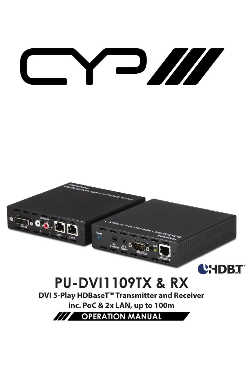
Seada TapPlay TP-U400 User manual

TapPlay™User Manual
TP-U400
Receiver: TP-U400
Transmitter: TP-DGH (HDMI dongle), TP-DGC (Type C dongle)
Document No. SD-MA-044
Document Version: 02

Contents
1. Overview ..........................................................................................................................................................1
2. Specification .....................................................................................................................................................4
3. Panel Layout.....................................................................................................................................................5
3.1 Hardware Interface ...........................................................................................................................5
3.1.1 TP-U400 Front Panel..........................................................................................................................5
3.1.2 TP-U400 back Panel...........................................................................................................................7
3.1.3 Factory Reset.....................................................................................................................................8
3.1.4 Dongle Front Panel............................................................................................................................9
3.2 Software Interface...........................................................................................................................11
3.2.1 Home Screen ...................................................................................................................................11
4. Installation......................................................................................................................................................13
4.1 Installation methods for the base unit............................................................................................13
4.2 Wiring Diagram................................................................................................................................14
4.3 Power Connection...........................................................................................................................14
4.4 Video Connection ............................................................................................................................15
4.5 Audio Connection............................................................................................................................15
4.6 LAN connection ...............................................................................................................................15
4.7 Use of USB devices ..........................................................................................................................16
5. Quick Start......................................................................................................................................................17
5.1 Mobile device: Wireless Connection...............................................................................................17
5.2 Pairing dongles with base unit ........................................................................................................17
5.3 Mirroring .........................................................................................................................................17
5.3.1 Windows PC/Mac with application .................................................................................................17
5.3.1.1 Options for Windows PC/Mac .................................................................................................19
5.3.1.2 Quad view mirroring................................................................................................................19
5.3.2 Mobiles Devices...............................................................................................................................20
5.3.3 Miracast on Android Devices and WIN10 PC ..................................................................................21
5.3.4 Chromecast on PC ...........................................................................................................................21
5.4 Preview Window .............................................................................................................................22

5.5 Whiteboard & Annotation...............................................................................................................22
5.5.1 Whiteboard .....................................................................................................................................22
5.5.2 Annotation.......................................................................................................................................25
6. Start video conferencing via USB-over-Wi-Fi technology ..............................................................................27
6.1 Start with application/dongles........................................................................................................27
7. WEBUI.............................................................................................................................................................28
7.1 Network settings .............................................................................................................................29
7.1.1 Wireless network.............................................................................................................................29
7.1.2 Ethernet...........................................................................................................................................32
7.1.3 Auto change password....................................................................................................................33
7.2 Display & Audio ...............................................................................................................................34
7.2.1 HDMI................................................................................................................................................34
7.2.2 Audio ...............................................................................................................................................36
7.2.3 Airplay screen quality......................................................................................................................37
7.2.4 Show the base device name and password when mirroring: .........................................................38
7.2.5 Home Screen background image.....................................................................................................39
7.3 Moderator control...........................................................................................................................40
7.4 System settings................................................................................................................................42
7.4.1 Buttons: ...........................................................................................................................................42
7.4.2 Date & Time.....................................................................................................................................43
7.4.3 Auto standby ...................................................................................................................................44
7.4.4 Language..........................................................................................................................................44
7.4.5 Reset................................................................................................................................................45
7.4.6 Configuration File ............................................................................................................................45
7.4.7 Series Port Setting ...........................................................................................................................46
7.4.8 Telnet switch ...................................................................................................................................46
7.4.9 Reboot .............................................................................................................................................47
7.5 Security Settings..............................................................................................................................48
7.5.1 Security level ...................................................................................................................................48
7.5.2 Login Password................................................................................................................................49
7.5.3 Connection password......................................................................................................................49

7.6 Firmware upgrade ...........................................................................................................................50
7.6.1 Firmware Update.............................................................................................................................50
7.6.2 Automatic Upgrading ......................................................................................................................50
7.7 Other settings..................................................................................................................................51
7.7.1 Auto create launcher.......................................................................................................................51
7.7.2 Clear history after meeting..............................................................................................................52
7.7.3 Developer tools ...............................................................................................................................52
7.8 UCC-Device manager.......................................................................................................................53
7.9 About device....................................................................................................................................54
8. Troubleshooting .............................................................................................................................................55

SD-MA-0441 V2.0
1. Overview
TP-U400 is a BYOM wireless presentation switcher designed for ease of use in conference room or
classroom applications with less cabling and cost. This product is compatible with most USB cameras
and conferencing audio solutions, such as speakerphones, AEC processors, video soundbars with
audio integration, etc.
TP-U400 features its own Wi-Fi access point and support popular mirroring technology such as Airplay
and Miracast from computers and phones. The product supports single view, 1x2 and 2x2 multiview
and can have up to 16 devices connected with preview. It can be incorporated with interactive display
or whiteboard to control source devices for manipulating or annotating. The use of TP-U400 can offer
a powerful presentation and collaboration environment for conference and meetings.
Key Features
TP-U400:
•Full wireless presentation and BYOM support
•Support wireless input up to 1080P@60Hz, and HDMI 2.0 output up to 4K@60Hz
•Support Windows/Android application and PnP HDMI/Type-C dongles for wireless connection
•Support wireless mirroring like Miracast
•Support USB peripherals like camera, mic, and speaker for wireless connection to PC/Mac
•Support mouse and keyboard control
•Support wireless touch back for PC/Android
•Fully compatible with VC platforms
•Support multiview up to 4 windows with preview
•Support PoE
•Support customisable home screen
•Built-in whiteboard and on-screen annotation
•Support WebUI for central management
•Low latency
•Best-in-class data security
•Support preview

SD-MA-0442 V2.0
TP-DGC/TP-DGH:
•Support wireless transmission from PC/Mac to base unit
•Support quick switch of the PC signal for less than 1s by tapping
•Dual color LED, indicating active source signal and power/link
•Support USB peripherals such as camera, mic, and speaker over Wi-Fi sharing
TP-U400 related devices and applications
A typical TP-U400 can work with two different types of dongles, ‘TapPlay’for Android/Windows/Mac
and Airplay for IOS. Depending on the application or size of the meeting room, users can purchase
more dongles, e.g., HDMI dongle/ Type C dongle if necessary.

SD-MA-0443 V2.0
Name
Description
Base Unit
Base unit TP-U400
Dongles/Transmitters
For PC/Mac to share the desktop/extended
desktop.
‘TapPlay’app
For Android/Windows/Mac devices to share
the screen.
Airplay for IOS
For IOS devices to share the screen.
Accessories List
ID
Name
Description
1
Antenna
3 pcs of antenna are included in the box. To
avoid damage, they are not pre-mounted.
The antenna can rotate for a better wireless
connection.
2
Power adapter
International plug inter-changeable power
adapter, of which the plugs include US,
Europe and UK standard.
3
Phoenix terminal
1 piece phoenix terminal for connecting the
RS232 port of the back panel.
4
Download Card
1 piece download card that user can find
related manuals on our website.

SD-MA-0444 V2.0
2. Specification
TP-U400 Specification
HDMI output
1x HDMI 19-pin female connector
Video Output Resolution
3840x2160@60Hz/30Hz, 1920x1080@60Hz, 1280x720@60Hz
Format Compliance
HDMI1.4/HDMI2.0
HDMI input / max. resolution
Maximum 1080P@60Hz via TP-DGH/DGC, app, and Airplay
HDCP
HDCP1.4/HDCP2.2
Compatible dongles
TP-DGH, TP-DGC
LAN port
2x RJ45: 1x 1000Mbps with POE, 1x 100Mbps
USB interface
3x USB3.0, 1x USB 2.0, 2x Type-C
Control
Keyboard, mouse, and interactive display touch back
Content Input
TP-DGH/TP-DGC, AirPlay, Miracast, Windows/Mac application
Audio Output (Analog)
1x 3.5mm audio female connectors
Control interface
WebUI, Telnet, 3.5mm Phoenix terminal/ RS232 interface
Multiview
Up to 4 simultaneously with adjustable layout
Number of simultaneous
connections
Minimum 16
Wireless transmission protocol
Wi-Fi IEEE 802.11 a/g/n/ac
Frequency band
2.4 GHz & 5 GHz
Data rate in wireless
Up to 1200Mbps
Latency
<100ms, min 20ms with low latency mouse cursor
Dimension (W x D x H)
220 x 120 x 34mm (incl. antennas 220 x 280 x 34mm)
Weight
0.74kg
Temperature
-4° ~ +140° F (-20° ~ +60° C)
Humidity (Storage / Operating)
20%-90%(non-condensing)
Power Supply
Power adaptor with exchangeable plugs (EU/UK/US) 12V/3A, POE
POE standard
POE plus - IEEE802.3af
Power Consumption
Maximum 36W
Security standard
WiFi: WPA PSK, WPA2 PSK - Video transmission encrypted with AES-256 bit +
RSA1024 bit

SD-MA-0445 V2.0
3. Panel Layout
About this chapter
The installation chapter gives an overview of the interface of TP-U400.
Overview
⚫Hardware Interface
◼TP-U400 Front Panel
◼TP-U400 Back Panel
◼TP-DGH/TP-DGC Front panel
⚫Software Interface
◼Home Screen
3.1 Hardware Interface
3.1.1 TP-U400 Front Panel
Note: Front USB port and type C port cannot be used at the same time, type C port is prior to USB
port.

SD-MA-0446 V2.0
ID
Name
Description
1
Front USB connector
USB port, for dongle pairing, mouse control,
USB touch screen etc.
2
Front Type-C connector
Type-C port, for dongle pairing.
3
Power Button
Turn on or off the device.
4
Back-lit LED indicator
RED: Initialisation
Flashing GREEN: Power on
Static GREEN: Ready to share
Static Cyan, Sharing
USB port
⚫The USB port can be used to pair dongles with the base unit.
⚫The USB port can be used to create or upgrade TapPlay Windows/Mac/Android applications by
clicking Download button, when a USB stick is plugged in.
⚫The USB port can be used to connect a USB-based touch screen or mouse/keyboard for
controlling when a PC desktop is mirroring to the screen.
Type-C port
The Type-C port can be used for pairing TP-DGC with base unit.
Mounting
The mounting points for the unit are located at the bottom of the base unit.

SD-MA-0447 V2.0
3.1.2 TP-U400 back Panel
ID
Name
Description
1
Line audio
output
2 channel analog audio output
2
RS-232
RS-232 port
3
Kensington
Lock
Standard Kensington Lock to security the unit
4
Rear Type-C
connector
Type C port for TP-DGC pairing
5
Rear USB3.0
connector
USB port for TP-DGH pairing, mouse control, USB touch
screen and USB device such as USB camera and speaker
etc.
6
Reset
Reset button to restore to the factory default setting
7
HDMI output
Connect an HDMI cable from this port to an
HD or 4K/HDMI2.0 display

SD-MA-0448 V2.0
8
LAN Ethernet
port 1
100Mbps Ethernet port
9
LAN Ethernet
port 2
1000Mbps Ethernet port and support POE
10
DC Power
socket
Power socket to boot up the unit
11
Antenna
fixture points
Screw up the included three antennas to these three
ports.
USB port
⚫The USB port can be used to pair dongles with the base unit.
⚫The USB port can be used to create or upgrade TapPlay Windows/Mac/Android applications by
clicking Download button, when a USB stick is plugged in.
⚫The USB port can be used to connect a USB-based touch screen or mouse/keyboard for
controlling when a PC desktop is mirroring to the screen.
3.1.3 Factory Reset
1. Start up the base unit.
2. When the Home Screen is shown up, press the reset button at the back panel of base unit. Press
this button with a narrow object, e.g., a paper clip until the ‘Factory Reset’page is shown up for
at least 2 seconds.
3. The base unit will reboot after 3 seconds.
4. If no ‘Factory Reset’ page showed up, press, and hold the reset button until the red LED in the top
panel is up, to execute the reset.

SD-MA-0449 V2.0
3.1.4 Dongle Front Panel
TP-DGH (left) and TP-DGC (right) are dongles, used for toggling the mirroring from personal PC or Mac
onto the main screen.
⚫When LED indicator is static green, it’s ready to mirror desktop onto the main screen.
⚫When LED indicator is static red, 1) it’s mirroring, 2) if the dongle is connected to the base unit,
that means pairing is done.
⚫When LED indicator is blinking Green, it indicates 1) the dongle is plugged in and initialising or
waiting for user to start the application, 2) if the dongle is connected to the base unit, that means
pairing/software updating is in progress.
⚫When LED indicator is Off (no light), it indicates 1) the dongle is not plugged in; 2) the dongle is
faulty; 3) the USB port of PC/Mac might be faulty.
ID
Name
Description
1
HDMI
connector
HDMI connector of the dongle can be plugged into a
PC/Mac for sharing screen.
2
USB connector
1) Power supply or 2) can be plugged into the base unit
for pairing or upgrading of dongles.

SD-MA-04410 V2.0
3
Type C (DP)
connector
Type C (DP) connector of the dongle can be plugged
into a PC/Mac for sharing screen.
4
Touching
button
Touch the sensor button to start mirroring desktop
onto the main screen. Touch again the sensor button to
terminate the sharing.
5
LED indicator
Indicates the status of the dongle.
Note: TP-DHC contains a fully functional type-C interface with DP Altmode inside, which supports
audio and video transmission. The type C connector on the PC also requires a fully functional type
C connector for mirroring.

SD-MA-04411 V2.0
3.2 Software Interface
3.2.1 Home Screen
ID
Name
Description
1
Wi-Fi Indicator
Wi-Fi Direct mode: Access point is enabled:
Wi-Fi Infrastructure mode: Wi-Fi connection to
router is established and the icon displays the
current signal strength: ·
A secure Wi-Fi connection is established, or
connection to a router failed:
Wi-Fi is not available:
LAN Infrastructure mode: Access point is disabled
2
ID
Wi-Fi name of the base unit access point.
3
PASS
Wi-Fi password of the base unit.

SD-MA-04412 V2.0
4
Password-timer
Display time until the password changes
automatically. This timer is only available when
‘auto change password’is activated.
5
Refresh Wi-Fi-
password
Generate a new password manually to secure the
Wi-Fi network.
6
TIME
Show time if LAN/Wi-Fi has access to a time server.
The time is displayed until the device power is cut
after disconnecting from the LAN/Wi-Fi
connection.
7
Security level
Security level 1-3 (display ONLY). The details for
the security features of the displayed level are
shown by clicking on the icon.
The settings can only be changed by administrator
in the WebUI.
8
Download Button
Creating & upgrading Launcher ‘TapPlay.exe’for
Windows, Mac, and Android to a USB stick.
9
Info
Show/Hide icons (1) - (6) and (10) in home screen.
10
Camera and
microphone
indicator icon
When TP-U400 is connected with a USB camera or
microphone, the icon will be displayed.
11
Preview & White
Board & Annotation
Previews for all connected dongles and mobile
devices and functions to operate them. The white
board and annotation function can also be found
by clicking the button.
12
Whiteboard icon
Whiteboard function
13
Info
Click to show ID and password when mirroring.
14
Annotation
Annotation function.
15
Wi-Fi IP
LAN IP
⚫Wi-Fi IP: address of the base unit in Wi-Fi
⚫Assigned IP: address of the base unit in LAN;
‘N/A’= no connection to network

SD-MA-04413 V2.0
4. Installation
This section gives an overview of the ways to install and connect the base unit.
4.1 Installation methods for the base unit
Introduction to the installation methods:
The base unit can be installed either by table mounting or wall mounting in a meeting room.
The articulated antennas are removable and rotatable for easier connection and better signal.
Attention: For optimal performance, install the base unit close to the display and avoid obstacles
between the base unit and dongles.
Required tools
• A drill (type of drill depends on the type of wall)
• 2 mounting screws (mounting screws are not included in the package) (between 6 and 8 mm)
How to install
1. Drill two holes in the wall.
2. Insert 2 flat screws into the 2 holes and fasten
3. At the bottom of the base unit, plug 2 flat screws into 2 holes of its smallest diameter to fasten.
Note: Mounting screws are not included in the box. The type of screws depends on the type of wall
(stone, wood, plasterboard, ...) the base unit is mounted to. Make sure the head of the screw is not
larger than the hole at the bottom of the base unit.
4. Place the base unit on the wall and fix it with the 2 screws.
Antenna placement rules
⚫The antennas should be oriented vertically, perpendicular to the ceiling and parallel to the walls.
⚫The antennas should be installed far enough (at least 50cm/1.6ft) from metallic surfaces to avoid
reflections and far enough (at least 1m/3.3ft) from other radio equipment that operates in the
same frequency range, e.g., other Wi-Fi access points, cordless telephone, microwave ovens. It is
also better to install antennas at least 15 cm (6 inches) from concrete walls.
⚫The best situation is a direct line of sight between antennas and transmitters. Any obstruction can
cause the signal to follow a longer propagation path, which may result in performance
degradation.
⚫Due to the radio pattern of the dipole antennas, the antennas should not be placed just above the
position of the user. The advised position for the antennas is at the side of the meeting room.

SD-MA-04414 V2.0
4.2 Wiring Diagram
4.3 Power Connection
The base unit can be powered by external power adapters.
How to connect the external power adapter
1. Connect the power adapter with the power lead and plug it into the power input of the base unit.
2. Choose the appropriate power plug (US, UK, or EU) to be installed on the power lead.
3. Plug the power lead into the wall outlet.
Note: Once the base unit is powered on, please use the POWER button with Status LED on the front of
the base unit to switch the unit ON and OFF.
Power over Ethernet
If the IP switcher supports POE (Power over Ethernet), it will power up the base unit without the use
of any external power adapter.

SD-MA-04415 V2.0
4.4 Video Connection
1. Connect the HDMI Output of the base unit to a 4K or Full-HD display by a HDMI cable.
2. Connect the power adapter to the base unit DC power socket, connect the power plug to an
outlet and switch the base unit on.
3. The system will then display the home page.
4.5 Audio Connection
The base unit can transmit the audio output of the PC/Mac, re-direct and send it with the video signal.
The audio will be output at line levels from mini jack socket 3.5mm connector and via the HDMI
output connectors simultaneously.
It’s up to the user to decide whether to send the audio signal together with the video signal.
How to connect separate audio
1. Connect an audio cable with mini jack socket 3.5mm connector into audio port of the base unit.
2. Connect the other side to the sound system of the meeting room.
PC/Mac Sound
By default, the internal speaker of PC/Mac will be muted, and the audio will be routed to the base
unit after PC/Mac successfully mirrors desktop to the main screen, which is to avoid repeated audio.
When sharing is terminated, local speaker will return to previous status and the volume on PC/Mac
can be adjusted.
4.6 LAN connection
The base unit can be connected to a local network or directly to a PC/Mac.
1. Connect an Ethernet cable with RJ45 connector into the LAN port of the base unit.
2. Connect the other side to LAN.
3. If the Ethernet switch supports POE (Power over Ethernet), it could power up the unit without the
use of external power adapter.
LAN connection can be used for:
⚫Network integration of the base unit in guest or company network.
⚫Telnet control the base unit.
⚫Maintenance purpose to access WebUI.

SD-MA-04416 V2.0
4.7 Use of USB devices
USB control: A USB mouse or touch screen can be connected to the base unit.
USB mouse
⚫For configuration of the home screen.
⚫Single click to select.
⚫Right-click to back to the Home Page.
⚫Long press the left button to open the contextual menus, same as right-click of a USB mouse.
Touch screen
⚫Click to select.
⚫Long press to open the contextual menus, same as right-click of a USB mouse.
External USB Devices over Wi-Fi Sharing
TP-U400 supports USB Camera and USB speakerphone over Wi-Fi sharing.
There are 3 USB ports and 1 Type C port in rear panel of TP-U400 for connecting the external USB
devices such as microphone and camera, to start meeting with all kinds of video conference software
such as Teams and Zoom.
This manual suits for next models
1
Table of contents
