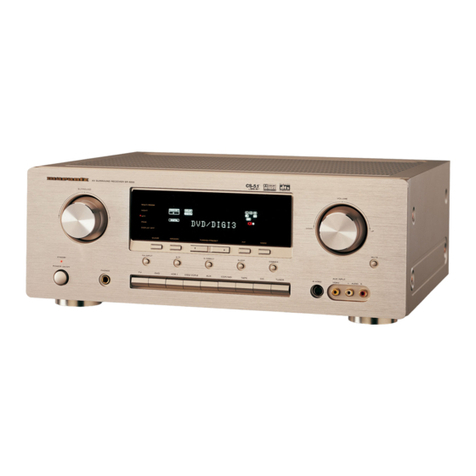
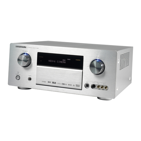
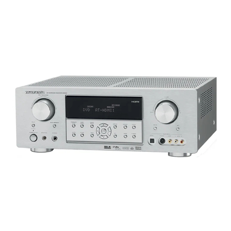
Marantz SR800 User manual

A
4
PYN
Rm
am
eam
ee
Ew.
model
SR800

MARANTZ
DESIGN
AND
SERVICE
Using
superior
design
and
selected
high
grade
components,
MARANTZ
Company
has
created
the
ultimate
in
stereo
sound.
Only
original
MARANTZ
parts
can
insure
that
your
MARANTZ
product
will
continue
to
perform
to
the
specitications
for
which
it is
famous.
Parts
for
your
MARANTZ
stereo
are
generally
available
within
72
hours
throughout
the
nation
via
a
toll-free
line
to
our
National
Parts
Depot
in
California.
The
sales
professionals
who
take
your
call
immediately
refer
to
their
own
desk
top
com-
puter
terminal
and
can
quickly
determine
the
availability
and
price
information
you
require.
If,
for
some
reason,
your
order
should
exceed
our
available
stock,
we
usually
can
instantly
provide
an
alternate
replacement
part
or
current
delivery
infor-
mation.
When
the
order
is
placed
and
confirmed,
the
computer
simultaneously
generates
‘‘hard
copy”
orders
at
the
distribution
center.
As
hard
copies
come
directly
from
the
computer
to
the
national
parts
depot,
your
requested
stock
is
assembled
and
prepared
for
shipment
and
placed
on
the
first
available
carrier
for
delivery
to
you.
ORDERING
PARTS
Phone
orders
will
eliminate
mail
delays,
and
we
encourage
the
use
of
this
method.
If
you
order
by
mail,
use
MARANTZ
parts
order
forms
which
are
available
from
our
National
Parts
Depot
located
at
the
following
address:
SUPERSCOPE
NATIONAL
PARTS
DEPARTMENT
20525
Nordhoff
Street
Chatsworth,
California
91311
Phone:
1-800-423-5108
1-213-998-9333
The
following
information
must
be
supplied
to
eliminate
delays
in
processing
your
order:
Complete
address.
Complete
part
numbers.
Complete
description
of
parts.
Model
number
for
which
part
is
required
(indicate
MARANTZ).
Account
number
(for
account
customers
only).
OWN
=
Direct
consumers
will
be
provided
with
the
current
retail
price
quotation
on
available
parts
in
order
to
advise
them
of
the
cost
of
the
parts
and
shipping.
OVERSEAS
PARTS
ORDERING
Parts
may
also
be
ordered
from
the
following
overseas
addresses:
CANADA
AUSTRALIA
JAPAN
Superscope
Canada,
Ltd.
Superscope
(Australasia)
Pty.,
Ltd.
Marantz
Japan,
[nc.
3710
Nashua
Drive
32
Cross
Street
(P.O.
Box
604)
3622
Kamitsuruma
Mississauga
Brookvale
2100
N.S.W.
Sagamihara
Shi
Ontario,
Canada
L4V
1M5
Australia
Kanagawa,
Japan
EUROPE
Marantz,
S.A.
Marantz
France
Marantz
Audio
U.K.
Ltd.
Marantz
GmbH
Avenue
Leopold
II,
2
Rue
Louis
Armand
9
London
Road,
203
Max-Planck-Strasse
22
7120
Peronnes-Lez-Binche
92600
Asnieres
Staines
D-6072
Dreieich
1
Belgium
Hauts-de-Seine
Middlesex
West
Germany
France
England
All
of
the
above
locations
are
fully
equipped
to
take
care
of
your
total
service
needs.
Because
various
countries
have
differing
configuration
requirements,
it
is
necessary
that
you
contact
the
service
facility
in
your
particular
country.
In
the
event
that
there
is
no
service
location
listed
for
your
country,
please
contact
the
nearest
facility
for
the
necessary
assistance.
name
Been
ual
z..
We
sound
better

TABLE
OF
CONTENTS
Section
Title
Page
4-4P
Ws
BOARDS:
4.0
&
okt
ho
ae
eas
S
Geet
oe
dele
gee
ree
We,
Ree
tants
A
a
tel
Be
aed
RS
ae
beter
ea
alt
ge
eal
cots
3
2.
TEST
EQUIPMENT
REQUIRED
FORSERVICING
1...
0.0...
.
ee
ee
ee
eee
eee
ee
tee
eee
3
3.
FM
ALIGNMENT
PROCEDURES
.........--
ce
eee
weet
eee
eee
ee
ee
eee
ee
ee
eee
tee
es
4
3.1
FM
IF
Alignment
2.0.0.0
-
00
cc
ee
ee
ee
ee
ee
ee
eee
eee
eee
eee
tee
eee
4
3.2
FM
RF
Alignment
.
22.206.
ee
eee
ee
eee
ee
tee
ees
4
3.3
Muting
Circuit
Alignment
2.2.22.
60
ccc
eee
eee
eee
eee
eee
eee
eee
ee
4
3.4
Multiplex
Alignment
Procedures
2.2...
ce
ee
ee
eee
eee
ee
eee
5
4.
AM
ALIGNMENT
PROCEDURES)
........
2...
e
eee
ee
eee
eee
ee
eee
eee
ee
eee
eee
5
4.1
AMIF
Alignment
2.2.0.0...
0.
2
ee
ee
ee
tee
eee
eee
eee
eee
5
4.2
AMRF
Alignment
2.0.0.0.
0
ec
cee
ee
eee
eee
eee
ene
ere
cent
tenes
eet
een
e
ener
5
5.
AUDIO
ADJUSTMENT
......
0...
cee
cee
ee
ee
ee
eee
ee
ee
eee
eee
eee
eee
ee
7
5.1
Voltage
Adjustment
.......
2-0
ee
ec
et
ee
te
ee
eee
eee
7
6:
VOLTAGE
CONVERSION
....
06s
cco
oe
os
eis
eee
eR
eee
ee
hae
oie
BO
ae
were
Gua
ee
re
eee
2
7
Fai
DIAG
RAMS®
20.
ies
sh
oie
ca
ice
ae
ele
kd
Gee
wan
ee
eat
als
ee
ates,
law
ee
Bieta
Measles
9S
care
NRG
8
leh
ga
No
OTE
ea
Sed
ERTS
8
FA
Block
Diagram
2:5.
ses
6
aod
secs
ee
estas
ow
gee.
Whe
eee
oe
Sears
eb
ane
ae
Sere,
eae
Ae
eran
Sea
el
ae
ea
eee
8
7.2
Tuner
Board
Schematic
Diagram
and
Component
Location-P100
..
2...
1
ee
ee
eee
eee
9
7.3
Main
Amp/Power
Supply
Board
Schematic
Diagram
and
Component
Locations-P700
..
1.1...
1
eee
ee
ee
eee
11
7.4
Volume/Balance
Board
Schematic
Diagram
and
Component
Locations-PEOO
-...-----
2-2
eee
eee
ee
eet
eee
12
7.5
Tone
Control
Board
Schematic
Diagram
and
Component
Locations-PFO0
...
2... 0...
eee
ee
ee
ees
St
astral
as
aoe
12
7.6
Pushswitch
Board
Schematic
Diagram
and
Component
Locations-PS00.
2...
2...
ee
ee
ee
eet
12
7.7
Headphone
Jack
Board
Schematic
Diagram
and
Component
Locations-PWO0
....
2.2...
1...
e
ee
eee
ee
eee
12
7.8
Speaker
Terminal
Board
Schematic
Diagram
and
Component
Locations-PW50
..
1.2...
cc
ce
ee
ee
ees
13
7.9
Speaker
Switch
Board
Schematic
Diagram
and
Component
Locations-PXO00
........--.2-2
02
eee
ee
ee
13
7.10
Stereo
LED
Board
Schematic
Diagram
and
Component
Locations-PY00
..
2.2...
ee
ee
ee
ee
13
7.11
Dial
Pointer
Lamp
Board
Schematic
Diagram
and
Component
Locations-PZ00
...
1.2.1...
ee
ee
ee
ees
13
7.12
Tuning
Meter
Lamp
Board
Schematic
Diagram
and
Component
Locations-PZ50
2.0...
1...
ce
ee
ees
13
8.
EXPLODED
VIEWS
AND
PARTS
LIST
2.0...
1.
eee
eee
eee
eee
14
8:4
(€01299)+
Front
Panels
5.6...
gees
eked
Se wo
ha
este
Ges
eRe
we
ee
eee
Ob
A
ww
oye
inn
ee
a
aS
14
$8.2"
[CO2-99]°
Top:
Cover:
csc)
sce
ace
Zaye
Mw
tanec
ds
oan
&
aviodies
ala
thlin
ce
Gla
Sie
na
Ebel
A
Sas
ee
eee
Roe
ee
Moet
te
eae
ao
aha
ee
15
8.3
‘[C03-99]
‘Rear:
Parelliccec:5sea-3
oala
Seep,
Se
OTS
eta
en
ede
ky
ie
WN
Rw
de
dne
a
eieh
eel,
git
aie
Deets
Mae,
a
a
genamend
16
8.4
[P01-99]
Front
Chassisand
General
Parts
2.0.0...
ee
ee
eee
ee
eee
eee
ete
17
8.5
(PQ2-99]
Chassis
and
Other
Parts
2.0...
cc
ct
ee
ne
ee
ee
ee
eee
eee
eee
eee
eee
eens
18
8.6
[HO1-99]
Packing
Materials...
2...
ee
ee
eee
eee
eee
eee
nents
19
G7
[Electrical
Parts:
ois:.s62
see
sao
Gon
dike-ar
Gouge
derin
de
a
Re
geet
eee
ota
ecle
Gatoretw
a
Spat
Beene
cae
Woe
Teie
aie
ae
laa
wh
a
oe)
9s
LA
we
20
9.
TECHNICAL
SPECIFICATIONS
«..
2.06500
620s
cd
ci
ein
ce
Se
el
ee
ee
eee
ee
le
One
re
oe
alee
25

INTRODUCTION
This
service
manual
was
prepared
for
use
by
Authorized
Warranty
Stations
and
contains
service
information
for
Maranz
Model
SR
800
Stereophonic
Receiver.
1.
P.W.
BOARDS
As
can
be
seen
from
the
circuit
diagram
the
chassis
of
Model
SR
800
consists
of
the
following
units.
Each
unit
mounted
on
a
printed
circuit
board
is
described
within
the
square
enclosed
by
a
bold
dotted
line
on
the
circuit
dia-
Servicing
information
and
voltage
data
included
in
this
gram.
manual
are
intended
for
use
by
the
knowledgeable
and
ex-
perienced
technician
only.
All
instructions
should
be
read
1.
Tuner............
mounted
on
P.W.
Board
P100
carefully.
No
attempt
should
be
made
to
proceed
without
a
good
understanding
of
the
operation
of
the
receiver.
2.
Main
Amp/Power
Supply
Se:
Seiad
eee
Fw
eas
mounted
on
P.W.
Board
P700
3.
Volume/Balance.....
mounted
on
P.W.
Board
PEOO
The
parts
list
furnishes
information
by
which
replacement
4.
Tone
Contro!l.......
mounted
on
P.W.
Board
PFOO
parts
may
be
ordered
from
the
Marantz
Company.
A
simple
5.
Pushswitch
........
mounted
on
P.W.
Board
PSOO
description
is
included
for
parts
which
can
usually
be
ob-
6.
Headphone
Jack
.....
mounted
on
P.W.
Board
PWOO
tained
through
local
suppliers.
7.
Speaker
Terminal
....
mounted
on
P.W.
Board
PW50
8.
Speaker
Switch
.....
mounted
on
P.W.
Board
PX00
9.
StereoLED........
mounted
on
P.W.
Board
PYOO
10.
Dial
Pointer
Lamp
.
Mounted
on
P.W.
Board
PZ00
11.
Tuning
Meter
Lamp...
mounted
on
P.W.
Board
PZ50
2.
TEST
EQUIPMENT
REQUIRED
FOR
SERVICING
This
table
lists
the
test
equipment
required
for
servicing
the
Model
SR
800
Receiver.
AM
Signal
Generator
aii
ieee.
Signal
source
for
AM
alignment
EM
Signal
G
Signa!
source
for
FM
alignment
MPX
ane
;
pahaed
Stereo
separation
alignment
and
trouble
Signal
Generator
shooting
Sound
Technology
Model
1000A
Distortion
measurements
Sinewave
and
squarewave
signal
source
Voitage
measurements
(AC)
Distortion
Analyzer
Audio
Oscillator
AC
VTVM
Sound
Technology
Mode!
1700A
Waveform
analysis
and
trouble
shooting
and
ASO
alignment
MPX
Oscillator
adjustment
(VCO)
Trouble
shooting
Tektronix
Model
T932
Philips
Mode!
3232
Fluke
Mode!
1900A
Oscilloscope
Frequency
Counter
Circuit
Tester
Fluke
Model
8000
“‘Digita!’’
Simpson
Mode!
313,
Triplet
Model
801
Simpson
Model
1379
DC
VTVM
Voltage
measurements
(DC)
Monitors
primary
power
to
amplifier
AC
Wattmeter
Monitors
amplifier
output
under
short
circuit
aa
Nttiee
gin
Wane
condition
Line
Voltmeter
Simpson
Model
1359
Sen
iters
potential
OF
poimaly
Rawer.to
amplifier
:
Superior
Electronic
Co.,
Variable
Autotransformer
Powerstat
Model
116B—-10A
Use
phono
plug
with
600-ohm
Shorts
amplifier
input
to
eliminate
noise
across
center
pin
and
shell
pickup
Provides
8-ohm
load
for
amplifier
output
Output
Load
(8
ohms,
:
+0.5%,
100W)
PammereiaOlede
termination
Output
Load
(4
ohms,
:
Provides
4-ohm
load
for
amplifier
output
+0.5%,
100W)
Commercial
Stade
termination
3
Adjusts
level
of
primary
power
to
amplifier
Shorting
Piug

*
A
dummy
resistor
of
47
kohms
must
be
connected
across
the
tape
output
terminals
before
alignment.
3.
FM
ALIGNMENT
PROCEDURES
(Selector
switch
in
the
“FM”
position)
Signa!
Source
Connection
Signal
Frequency
indicator
Connection
Set
Dial
Pointer
to:
Adjust:
3.1
FM
IF
ALIGNMENT
Oscilloscope
to
L106
for
maximum
and
Sweep
generator
to
10.7
MHz
JVO2
(TAPE
OUT)
: }
symmetric
response.
4
market
at
Quiet
point
on
point
()
through
10.6.
10.7
and
nee
.
6,10.7
a
and.
i
5pF
capacitor
FOS
MIE
|
Oscilloscope
to
L201
for
maximum
and
:
|
JVO2
(TAPE
OUT)
symmetric
response.
Repeat
steps
1
and
2.
3.2
FM
RF
ALIGNMENT
i
L105
for
maximum
87.4
MHz
87.4
MHz
with
i
tuning
gang
closed.
Output.
[i
RF
generator
to
.
FM
antenna
108.
2
MHz
108.2
MHz
with
C114
for
maximum
terminals
@®
through
matching
network
VTVM
to
LorR
channel
output
(JVO02)
tuning
gang
open.
output.
L101,
L103
for
(300
ohms,
balanced)
90
MHz
maximum
output.
Maintain
RF
level
oe
below
limit.)
(J036)
Ant.
RF
trimmer
for
106
MHz
Repeat
steps
1
to
4.
maximum
output.
Check
overall
response
curve
and
repeat
above
steps
as
necessary
to
obtain
maximum
sensitivity.
L201
lower
core
for
FM
No
connection
No
signal
~
-_
TENG
terete
pointer
indicated
its
center.
Distortion
meter
to
L201
(primary
core
upper)
L
or
R
channe!
out-
for
minimum
distortion.
FM
generator
1
mV
put
(JVO2)
output
to
FM
antenna
terminals
®
through
98
MHz
98
MHz
matching
network
(300
ohms,
balanced)
(JO36)
3.3
MUTING
CIRCUIT
ALIGNMENT
RF
generator
12.5uV
[R207
for
12.5uV
output
to
FM
antenna
VTVM
to
Rort
threshold
level.
{During
terminals
@
through
98
MHz
channel
output
98
MHz
the
adjustment
turn
matching
network
(JVO2)
the
FM
MUTING
push-
(300
ohms,
balanced)
(JO36)
switch
‘“‘ON").

Signal
Source
Connection
Signal
Frequency
3.4
MULTIPLEX
ALIGNMENT
PROCEDURES
(Selector
switch
in
the
“FM”
and
STEREO/MUTING
position)
Indicator
Connection
Set
Dial
Pointer
to:
Adjust:
RF
generator
to
FM
antenna
terminals
through
matching
network
(300
ohms,
balanced),
with
ImV
FM
stereo
simulator
RE
level
and
100%
modulation
(pilot
9%)
(JO36)
No
modulation
Frequency
counter
to
point
(J301)
R304
so
that
frequency
counter
may
precisely
read
19
kHz.
VTVM
to
right
Stereo,
left
éhannel
ouggur
utpu
1,000
H
Cae)
(JV02)
:
VTVM
to
left
Stereo,
right
channel!
output
(1,000
Hz)
(JVO2)
98
MHz
R313
for
minimum
output
and
same
separation
in
both
channels.
4.
AM
ALIGNMENT
PROCEDURES
(Selector
switch
in
the
‘““MW”
or
‘““LW”
position)
Signal
Source
Connection
Sweep
generator
to
AM
sweep
input,
Signal
Frequency
450
kHz
marker
RF
generator
to
AM
antenna
terminals
through
IHF
dummy.
525
kHz
Indicator
Connection
4.1
AM
IF
ALIGNMENT
Oscilloscope
to
point
©
(JAQ6)
4.2
AM
RF
ALIGNMENT
1,630
kHz
VTVM
to
Lor
R
600
kHz
channel
output
(JV02)
1,400
kHz
Repeat
steps
2
and
3.
Set
Dial
Pointer
to:
Quiet
point
on
band.
520
kHz
with
tuning
gang
closed.
LAOS,
LAO6
for
maxi-
mum
and
symmetric
response.
LAO4
for
maximum
output.
1,630
kHz
with
tuning
gang
open.
O.S.C.
trimmer
for
maximum
output
©.
600
kHz
LO51
for
maximum
output.
1,400
kHz
Ant.
trimmer
for
maximum
output
®.
Repeat
steps
1
to
4
as
necessary
to
obtain
maximum
sensitivity.

Lo51
AM
ANT
coil
™.
@
©
LAOS
LAOS
COIL
[1
@®
QaAo!
0402
|
LAO6
|
AM
IFT
SS
AM
SWEEP
INPUT
=
@
—
sacs
\
O))
One
commen
tacaparomeen
ced
rc)
FM
osc
\
om
~
Q
(i
O
(DO)
©
LIO6
py
TC4
\
O
[Lona
L
am
osc
ss
—_
\
oe
O&
FM
IFT
(H)
(@)
Tce
ST
\
osc
TC
Sy
@)r3!3
©
eM
Re.
©
'
QD
L302
FM
SEPARATION
~~
|
&
ADs.
ma
oF)
t
—
Q202
©
L103
D
ach
Q301
7
4
TCS
mune
be
i)
L201
2
es)
3002
UPPER:
MONO
DISTORTION
(j
\
——
J301
©
me
LOWER:
TUNING
oe
:
aTAE
P.
i)
(fF)
METER
ADJ
®
R304
R223
Qjrmmutine
()
TC!
§
VCO
take
R235
ADJ.
FM
ANT
Lio
R224
col.
Figure
1.
Adjustment
Point
Locations
Figure
2.
Dial
Stringing

5.
AUDIO
ADJUSTMENT
6.
VOLTAGE
CONVERSION
5.1
VOLTAGE
ADJUSTMENT
To
convert
the
unit
to
a
different
power
source
voltage,
1.
Turn
on
the
POWER
pushswitch
and
connect
a
DC
voit-
change
the
position
as
illustrated
in
the
drawing
below.
meter
across
the
J837
and
J723.
2.
Check
that
DC
voltmeter
reading
is
34
+1
V.
CAUTION:
DISCONNECT
POWER
SUPPLY
CORD
FROM
AC
OUTLET
BEFORE
CONVERTING
VOLTAGE.
DO
NOT
DISASSEMBLE
THE
VOLTAGE
SELECTOR
ABSOLUTELY.
~
”
_——
(N)
Version
(Note
on
safety:
The
parts
marked
with
4
are
important
parts
on
the
safety.
Please
use
the
parts
having
the
designated
parts
numbers
without
fail.)
FTZ
REGULATION
Instruction
for
the
use
in
the
range
other
than
specified
in
FTZ
codes.
Achtung
fiir
die
Leute,
die
in
dem
Gebiet
wohnen,
wo
die
FT
2-Bestimmungen
vorherrschend
sind.
Sollte
das
Gerat
auch
fiir
Frequenzen
auszerhalb
des
in
den
FTZ-Bestimmungen
angegebenen
Bereiches
empfangebereit
sein,
bitten
wir,
den
Bereich
durch
Nachstellen
des
Kernes
in
der
Oszillatorspule
(in
der
Abbildung
mit
“FTZ"
gekennzeichnet)
so
zu
korrigieren,
dass
er
den
Bestimmungen
entspricht.

7.
DIAGRAMS
7.1
BLOCK
DIAGRAM
LW3LSAS
H3NV3dS
TOMLNOD
1OULNOD
378381
ssv@
7
WALSAS
wanvads
*HOMLIN
4N09
3NOL
S2
HOLIMS
6)
yanvads
dav
NIVW
SAaNOHd
OV3H
>
|
HOLVAN
“AL
TAaNNVHO
¥3HLO
woud
HOLIMS
LHOLINOW
adVL
ssanaqnoy
C2
ES
ey)
US
ee
oan
Wi
XHOMLIN
SS3Nan01
HOLIMS
i
ma
a
———CE)
ino,
13dV1
==
Os
Tt3dVi
ORLNOD
JONVIVE
1OULNOD
aWNTOA
fee
Linauia
40193130
bsoe
aw
HLONAHLS
TWNOIS
aw
4!
13031
WY.
wy
5
U3L3N
ONINAL
V3A37
¥311I3
SONINAL
Wd
¥300930
0331S
XdW
LINDYID
SNILNW
40193130
Wd
‘TOV
NOLLWu
das
“rav
13A31
ONLLAN
dV
ONOHd
9s0
W901
wv
xn
———©)
onona
err
dWV
du
wy
VNN3LNV
OU
3L1YU
3d
WY
7
OND
USL
noe
Wd
Wi

7.2
TUNER
BOARD
SCHEMATIC
DIAGRAM
AND
COMPONENT
LOCATIONS
—
P100
ee
ne
en
ea
RIO
R204
e203
Reor
8
oo
72
aioe
'**
Lio
220
0.04
Foo:
18)
T42
zn
x
6123
0.01
058-125
L102
L103
C108
5p
a
<%
QE
R2
Abs:
oé|
3
|reet
66x
L101
Py
1
{)
3
a
noose
(Soy
°
Lea
|
rigs
Li04
3
F202
10K
bo
R2i2
6.
|
38
5
te
2
gs
-
:
cy
88
F201
s
38
s
9
sfe
s
2
lo
=
=.
8
ss
bg
|&
s|
8
2]
|e
a
ra
8
=
mn
|
ot
2 S
a
oo
R201
a
R205
8210
i]
S
87s
2: Py
330
2
560
3
‘
8 8
é
:
8
214
°
of
0x
i
C106
*To.02
i
;
t
+
A
s202|
1
t
it
we
ANB
42
|
W——Pt
C216
0.47/50v
RRR
az04
a
R26
fit—
CH
pig
MW
=
370
Carr
orev
|
tb
Tox
QIO3
haz
RII4
100
2
cae
cai
R301
Bia
oe
eo,
§
dee,
|
fest]
(else
1
ye
Ss
21s
>
x
R2I7
s102
Ks]
3
2
R334
oO
2|
2
2
100K
k
et
=
s,
Fe
Oe,
‘cazift
101
sy
=
e-_
j5.|
7
cad
cAa0s
aor
r
aw
R335
3.3K
R222
22k
223
1O/IBV
ry
Par
R304
5k
ae
$
R303
15k
€304
33/50V
seit
us
f
328
0302
y
908:
R305
306
tk
0.22/50V(N.P)
R333
2.7k
130%
£305
i
22/50"
aoe
3
301
22k
»-o-6-o-4
5
24
24
24 20
20
145
sack
Q301
ie)
145
5
145
26
12
37
108
108
6!
61
oO
Rage
W326
U
ance
O-O-O-O-O-O
3S
c320
047/209
cata
cai
lo303
fr
1
Cor
ad
ae
aar/gov
|
heis
RAL!
33K
are
WW
0
33k
30
ark
raes
|
33K
haces
303
CAl2
47p
)
R307
22k
R317
33x
R35
+
33K,
bi
:
¢307
HH.
302
ite
4709
C313
R319
C315
toriev
27k
0.47/50¥
cio
ts
oat/sovt
>
R306
R325
33)
327
m
R312
armnev
Te
2'9p5,,
am
22k
39K
100
|
|
tJ
2
Lid
R332|
c3i2*
R313
cit
00
tovtev
500k
107 16v
SEP
ADs.
v3041
204
[
7
lyaos,
coe
—
ce
ee
—-
vor
cvo2z
sdeetlel
0.01
1
Lo;
bh
[__}
to!
caos
0.012
411
0.0033
1421
220
16!
4}
+
AW
ol
]
|
|
RAll
270k
6+
feel
R409
160K
rn
C403
479
tT
a
we
+
407
oot
a
{
|
J
00s
Oo
T ®
Io
—
R405
R40:
R407
390%
‘cylGel
‘36k
470
Rai?
16!
C417
C403
2b
220k
I
r-—
'220p
©
100/10V"
To!
WOR
I5l
cal
ca06
o
220p
ove
Rai
Det]
©>+0)
R406
ages
kiadied
©
3208
[|
Sek
470
me
Seon
cals
O4+6
|
FOxd
FBS
|
|
raze
ace
[208
©
*e
‘470
(a
"7
3.3/50¥
220
}
>
F308
r
R420
+
Raoz
o
22k
22k
c4o4
47°
R410
160K
R412
270k
RaI4
22k
cattooe
cal2
0.0033
PHONO
AMP
4t—0
329
0.04
meme
meee
e

ee
i
t
sea
L302,
£30
Cl
10

TP700
MAIN
AMP
and
POWER
SUPPLY
A723
220K
RIOT
33%
-C706.0.5p
|.
RTIO
3.3%

TONE
CONTROL
BOARD
SCHEMATIC
DIAGRAM
AND
COMPONENT
LOCATIONS
—
PFOO
[PROS
TONE
CONPONENT
prt
crol
ae
AFOO
Wak

P
OUT
TERMINAL
[oo06
9
swe
Boffo

8.
EXPLODED
VIEWS
AND
PARTS
LIST
8.1
[C01-99]
FRONT
PANEL
PART
NO.
100H063400
2112158010
100H063013
2112063052
2112160020
2112160030
51280306B0
5128030880
51280308B0
2112303010
2276005050
2112259032
DESCRIPTION
023B
004B
@(N):
for
Europe
@(A):
for
Australia
DESCRIPTION
Front
Panel
Assembly
Window,
Dial
Escutcheon,
Escutcheon,
AL
Bracket
(R)
Bracket
(L)
B.H.
Tapped
Screw
B3
x
6
B.H.
Tapped
Screw
B3
x
8
B.H.
Tapped
Screw
B3
x
8
Mask
Ciamper
Bushing
PART
NO.
6
|
6
|
2112154010
6
16
|
2112115010
023B
1111
|
2116154020
025B
{5 {5
|
2112154020
040B
|2
|
2}
51100308A9
041B
|3
|3
|
51280308B0
Knob
Spring
Knob,
Tuning
Knob
B.H.M,
Screw
B3
x8
B.H.
Tapped
Screw
B3
x
8
14

15
8.2
[C02-99]
TOP
COVER
2133257502
010d
Case,
Wood
F.
Washer
Screw
B4
x
20
B.H.
Tapped
Screw
B4
x
10
Lid,
Bottom
Cover
2932861012
e@(N):
for
Europe
@
(A):
for
Australia

8.3
[€03-99]
REAR
PANEL
(A)
Version
e@(N):
for
Europe
(A):
for
Australia
Fuse
1AT
250V
Jack,
Fuse
Holder
Terminal,
Ground
Terminal,
Antenna
Plug,
Voltage
Selector
Plug,
AC
Inlet
FS10100800
YJ08000290
Y¥
L03010240
YT01040210
BY05060013
YP04000590
100H160252
100H
160234
51280308U0
51280308U0
51280308U0
51280308U0
51280308U0
1455259040
51420308TO
Bracket,
Rear
Panel
Bracket,
Rear
Panel
B.H.
Tapped
Screw
B3
x8
B.H.
Tapped
Screw
B3
x
8
B.H.
Tapped
Screw
B3x
8
B.H.
Tapped
Screw
B3
x8
B.H.
Tapped
Screw
B3
x
8
Bushing
O.C.H.
Tapped
Screw
3
x
8
LC11540040
|
ChokeCoil,
150uH
ZC02006040
A.C.
Power
Cord
2112265010
Indicator
16

8.4
[P01-99]
FRONT
CHASSIS
AND
GENERAL
PARTS
1
|
100H160012
6
|
51280308B0
8
|
51100308A9
2
|
51282605B0
1
|
100H
160032
1
|
5128030880
1
|
100H273012
100H160023
51280308B0
N=
17
Bracket,
Front
Chassis
B.H.
Tapped
Screw
B3x8
B.H.M.
Screw
B3x8
B.H.
Tapped
Screw
B2.6
x5
Bracket
B.H.
Tapped
Screw
B3
x
8
Flywheel
Bracket
B.H.
Tapped
Screw
B3x8
141
|
100H302012
4
|
4
|
51280308B0
1
|
1
|
2112274042
2
|
2
|
51280312B0
2
|
2
|
2276005050
1117
|
2112303052
2
|
2276262500
2
|
2276262500
1M11000010
$RO00040040
SP02010330
e(N):
for
Europe
e@
(A):
for
Austratia
DESCRIPTION
Dial
B.H.
Tapped
Screw
B3
x
8
Reflector
B.H.
Tapped
Screw
B3
x
12
Clamper
Mask
Pulley,
(K)
Pulley,
(K)
D.C.
Meter
Rotary
Switch
Push
Switch,
Power

8.5
[P02-99]
CHASSIS
AND
OTHER
PARTS
>
PART
NO.
DESCRIPTION
PART
NO.
e@
(A):
for
Australia
DESCRIPTION
003F
OO5F
OO6F
O11F
012F
O14F
O15F
020F
023F
025F
201F
202F
203F
Q03H
001i
002i
009i
012i
013i
020i
ae
oe
ee
=
ene
nasr
NNN
SARC
=
2
NNN
AAP
HAH
HS
-
Baypyenas
2a
we
eo
2112105014
2112105022
2112126012
51280308B0
51280410B0
2112271012
1502271010
51260310B0
51280308B0
51280308B0
2133005010
2116056012
2259109040
2259109060
2112109010
72040805A0
2112159010
71101689L0
72040805A0
2112103023
2112103012
2112303033
Chassis,
{L)
Chassis,
(R)
Stay
B.H.
Tapped
Screw
B.H.
Tapped
Screw
Holder
Holder
B.H.
Tapped
Screw
B.H.
Tapped
Screw
B.H.
Tapped
Screw
Ciamper
Buffer
Shield
Shield
Shield
String
(10)
Drum
Spring
String
(180)
Pointer
Pointer
Mask
B3x8
B4
x
10
B3
x
10
B3x8
B3x8
0071L
{1}
1
|
100H267010
O04tL
[141
|
2112271020
OOSL
[141
|
2112272013
OO6L
|1]
1
|
51280308B0
00O7L
{14
1
|
100H160040
OO8L
|2j
2
|
51280308B0
O10L
|1]1
|
2133160030
011L
|2|
2
|
51280308B0
012L
|2{|
2
|
5128030880
O15L
}11)1
|
2112160050
017L
|2]|2|51280308B0
018L
|3]3
|
51280308B0
O19L
|1;1
|
100H160052
022L
j1
1
|
51100308B0
024L
|2)}
2
)51780316B0
O26L
|
11/1
|
5128030880
027L
|
1}
1
|
62030049W0
ALoOO1
|}1
TS16619050
ALO001
1
|
TS16619040
L051
|1j1|LF11000242
$S06040020
Heatsink
Holder
Pole
B.H.
Tapped
Screw
Bracket
B.H.
Tapped
Screw
Bracket
B.H.
Tapped
Screw
B.H.
Tapped
Screw
Bracket
B.H.
Tapped
Screw
B.H.
Tapped
Screw
Bracket
B.H.M,
Screw
B.H.
Tapped
Screw
B.H.
Tapped
Screw
Lug
Power
Transformer
Power
Transformer
Antenna
Coil
Slide
Switch
@(N):
for
Europe
B3x8
B3
x8
B3
x8
B3x8
B3
x8
B3
x8
B3
x8
B3
x
16
B3x8

8.6
[H01-99]
PACKING
MATERIALS
19
rn]
Sa
Wore
awa
PART
NO.
DESCRIPTION
100H801030
2112809013
2112809020
2918107250
9090909040
9526019060
100H851310
100H851220
9526019030
Packing
Case
Cushion
Cushion
Sheet
Polyethy
Sheet
Serial
NO.
Card
Instructions
Instructions
Serial
No.
Card
PART
NO.
100H856010
9013025010
2864804010
2731821010
9560000043
9631000090
2ZA02000070
2C01805020
Circuit
Diagram
Polyethy
Bag
Sleeve
Silicagel
Hang
Tag
Guarantee
Card
EXT.
Antenna
A.C.
Power
Cord
DESCRIPTION
@(N):
for
Europe
(A):
for
Australia
Table of contents
Other Marantz Receiver manuals

Marantz
Marantz SR7008 User manual

Marantz
Marantz SR4002 User manual

Marantz
Marantz 2600 User manual

Marantz
Marantz SR4120 User manual

Marantz
Marantz SR7300 User manual

Marantz
Marantz SR5004 User manual

Marantz
Marantz SR6005 User manual

Marantz
Marantz SR5008 User manual

Marantz
Marantz SR6005 User manual

Marantz
Marantz SR4400 User manual

Marantz
Marantz SR5004 User manual

Marantz
Marantz SR 8100DC User manual

Marantz
Marantz SR-12S1 User manual

Marantz
Marantz SR-6001 User manual
Marantz
Marantz SR4023 Quick start guide

Marantz
Marantz NR1605 User manual
Marantz
Marantz SR7010 User manual

Marantz
Marantz NR1200 User manual

Marantz
Marantz SR5006 User manual

Marantz
Marantz SR5005 User manual